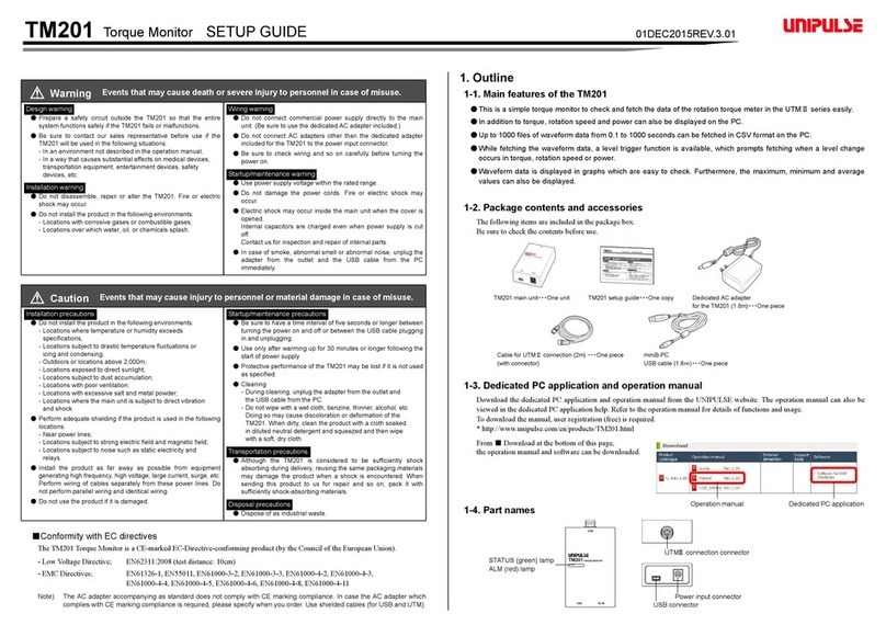
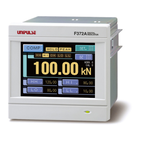
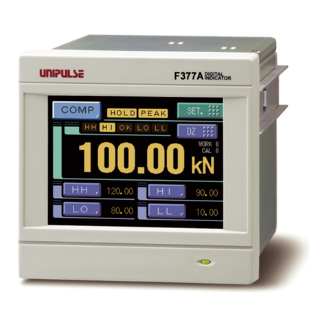
Unipulse F320 User manual

F320
DIGITAL INDICATOR
17 May. 2012
Rev. 1.07
OPERATION MANUAL

INTRODUCTION
INTRODUCTION
The F320 is a digital indicator for a strain gauge sensor, DIN96×48mm in size.
It is best suited for quality control in production lines, including pressure load control of
pressing, pressurizing, caulking, etc., and torque control of rotating devices.
The RS-485 (protocol; Modbus-RTU) is included as standard, which facilitates introduction
into a system that is formed by using the Modbus protocol.
To take full advantage of the F320’s excellent performance and to use it safely, carefully read
this operation manual and properly understand the descriptions in this manual before use.

SAFETY PRECAUTIONS
SAFETY PRECAUTIONS
Be sure to read for safety.
In order to have an F320 Digital Indicator used safely, notes I would like you to surely follow
divide into and , and are indicated by the following documents. Notes
indicated here are the serious contents related to safely. Please use F320 after understanding the
contents well.
WARNING
CAUTION
WARNING
Misuse may cause the risk of death or serious
injury to persons.
CAUTION
Misuse may cause the risk of injury to persons
or damage to property.

SAFETY PRECAUTIONS
WARNING
●For the entire system to function safely when the F320 becomes faulty or malfunctions,
provide a safety circuit outside the F320.
●Do not modify the F320. Doing so may cause fire or electric shocks.
●Do not install in the following environments.
- Places containing corrosive gas or flammable gas.
- Where the product may be splashed with water, oil or chemicals.
●Do not connect a commercial power source directly to the signal input/output
terminals.
●Be sure to ground the protective ground terminal.
●The attached AC cable is designed for domestic use in Japan, and its rating is 125V
AC, 7A. For use at voltages exceeding the rating and for overseas use, have a
separate AC cable prepared.
●Before performing the following, make sure that no power is applied.
- Attachment/detachment of connectors of options, etc.
- Wiring/connection of cables to the signal input/output terminals.
- Connection to the ground terminal.
●For connection to the signal input/output terminals, check the signal names and pin
assignment numbers, and then carry out wiring properly.
●After wiring, be sure to mount the attached terminal block cover. Otherwise, it may
cause an electric shock.
●To take measures against lightning surge, install a lightning surge protector (optionally
available).
●Before applying power, carefully check the wiring, etc.
Warning on design
Warning on installation
Warning on wiring

SAFETY PRECAUTIONS
WARNING
●Use at a proper power supply voltage.
●Do not damage the power cord. Doing so may cause fire or electric shocks.
●Do not touch any signal input/output terminal while applying power. Doing so may
cause electric shocks or malfunctions.
●If the cover of the main body is opened, it may cause an electric shock internally. Even
if the power is off, the internal capacitor is charged. Contact us for internal inspection
or repair.
●In the case of smoke, an abnormal smell or strange sound, immediately turn off the
power, and disconnect the power cable.
Warning during startup and maintenance

SAFETY PRECAUTIONS
CAUTION
●Use the F320 as it is incorporated in a control panel, etc.
●Do not install in the following environments.
- Where the temperature/humidity exceeds the range of the specifications.
- Outdoors, or where the altitude exceeds 2000m.
- Places containing large quantities of salt or iron powder.
- Where the main body is directly affected by vibrations or shocks.
●Take adequate shielding measures when using at the following locations.
- Near a power line.
- Where a strong electric field or magnetic field is formed.
- Where static electricity, relay noise or the like is generated.
●Tighten the screws for the signal input/output terminals at the specified torque.
If they are loose, shorts, fire or malfunctions may occur.
Tightening torque: 0.2 – 0.6N•m
●For sensors, external inputs/outputs and options, use shielded cables.
●For turning on/off the power, be sure to keep intervals of 5 seconds or more.
●If the F320 is not used by the specified method, its protective performance may be
impaired.
●When the F320 is shipped, spacers made of corrugated cardboard are used as
cushioning materials.
Though it is factory-designed so that shocks can sufficiently be absorbed, breakage
may result if shocks are applied when the spacers are reused for transportation. If you
send the F320 to us for repair, etc., take adequate measures against shocks by using
polyurethane materials, etc., separately.
●If you dispose of the product, handle it as industrial waste.
Caution on installation
Caution on wiring
Caution during startup and maintenance
Caution during transportation
Caution during disposal

CONFORMITY TO EC DIRECTIVES
The F320 digital indicator conforms to EC directives (based on the EC Council of Ministers),
carrying a CE mark.
・Low-voltage directive:IEC/EN61010-1:2001(overvoltage category II)
・EMC directives: EN61326-1:1997, A1:1998, A2:2001
EN55011:1998, A1:1999 ClassA
EN61000-3-2:2000
EN61000-3-3:1995, A1:2001
EN61000-4-2:1995, A1:1998, A2:2001
EN61000-4-3:1996, A1:1998, A2:2001
EN61000-4-4:1995, A1:2001
EN61000-4-5:1995, A1:2001
EN61000-4-6:1996, A1:2001
EN61000-4-8:1993, A1:2001
EN61000-4-11:1994, A1:2001
RoHS-compliant product
The parts and attachments (including the instruction manual, packaging box, etc.) used for
this unit are compliant with the RoHS Directive restricting the use of hazardous substances
with regard to adverse effects on the environment and human body.
What is RoHS?
It is an abbreviation for Restriction on Hazardous Substances, which is implemented by the
European Union (EU). The Directive restricts the use of six specific substances in electric and
electronic equipment handled within EU borders. The six substances are lead, mercury,
cadmium, hexavalent chromium, PBB (polybrominated biphenyls), and PBDE
(polybrominated diphenyl ethers).
EN61000-4-5 (lightning surge immunity)in the EMC directives applies to
the F320 body and lightning surge protector in combination.
For the connection of the lightning surge protector, see page 14.
Please inquire of our sales person about the RoHS-compliance of the option.
CONTENTS OF THE PACKAGE
The following are contained in the package.
Be sure to check before use.
* :It is attached only at the AC power source specification.
AC cable*: One
Terminating resistance: One 3P-2P conversion adapter*: One
F320 operation manual: One
F320
DIGITAL INDICATOR
OPERTATION MANUAL
㧲㧟㧞㧜
㧰㨕㨓㨕㨠㨍㨘
㧵㨚㨐㨕㨏㨍㨠㨛㨞
㧴㧵 㧻㧷
㧸㧻㨃
㧼㧱㧭㧷 㧴㧻㧸㧰
㧲㧺㧯
㧳㧭㧵㧺
㧯㧭㧸
㨆㧱㧾㧻 㧴㧻㧸㧰
F320: One
Ferrite core
(With binding band)
for power cable*: One
Ferrite core
(With binding band)
for sensor cable: One
(For RS-485)

CONTENTS OF THE PACKAGE
ࠩࠟࡀ
࠽࠶࠻㧹㧞
࠽ࡌࠦࡀࠫ㧹㧞㧝㧜㧔㐳㧕
࠽ࡌࠦࡀࠫ㧹㧞㧤㧔⍴㧕
ࠬࠢࡘࡀࠫ
ࠤࠬ㧔㧲㧯㧺㧙㧟㧢㧜㧯㧜㧟㧞㧙㧮㧕
ࠦࡀࠢ࠲㧔㧲㧯㧺㧙㧟㧢㧝㧶㧜㧟㧞㧙㧭㨁㧕
Case (FCN-360C032-B): Two Screws: Two M2 nuts: Four
Connector (FCN-361J032-AU): One
M2×8 pan-head machine screws (short): Two
M2×10 pan-head machine screws (long): Two
Washers: Two
BCD output connector: One set (when the BCO option is equipped)
Case (two)
Screw (two)
Connector
M2×8 pan-head machine screw (short) (two) M2×10 pan-head machine screws (long)
M2 nut (four)
Washer (two)
Assembly
About the power cable
・The power cable attached to this product as standard equipment can be
used in the AC100V power supply in Japan. (Official ratings voltage
AC125V)
Please use the power cable authorized in the country when you use this
product outside Japan.

CONTENTS
CONTENTS
1.FUNCTIONAL DESCRIPTIONS .............................................1
1-1.Front Panel ............................................................................................ 1
1-1-1Status Display ..................................................................................... 1
1-1-2Numerical Display ............................................................................... 2
1-1-3Setting Key Pad ................................................................................... 3
1-2.Rear Panel ............................................................................................. 5
1-2-1Protective Ground ............................................................................... 5
1-2-2Frame Ground (Frame terminal) ........................................................ 5
1-2-3Options Slot ......................................................................................... 5
1-2-4AC Power Input Terminal Block ........................................................ 6
1-2-5Signal Input/Output Terminal Block .................................................. 6
2.INSTALLING IN A CONTROL PANEL ....................................8
3.CONNECTION ........................................................................9
3-1.Connecting Strain Gauge Sensor ..................................................... 10
3-2.Connecting Power Input Terminal .................................................... 12
3-2-1AC Spec. ............................................................................................ 12
3-2-2DC Spec. ( Depending on the request at the time of order ) ......... 15
3-3.Connecting High / Low Limit Relays ................................................. 18
3-4.Connecting Hold and Digital Zero Signals ....................................... 19
3-5.Connecting Analog monitor Output (VOL OUT) .............................. 20
4.SETTING MODE CONFIGURATION ....................................21
4-1.Selection of Setting Items .................................................................. 21
4-2.Display of Setting Items ..................................................................... 23
4-3.List of Values ...................................................................................... 25
4-4.Setting Procedure ............................................................................... 28

CONTENTS
5.CALIBRATION ......................................................................29
5-1.Equivalent Input Calibration Procedure ........................................... 30
5-2.Actual Load Calibration ..................................................................... 36
6.SETTING OF FUNCTIONS ...................................................42
6-1.High /Low Limit Value ........................................................................ 42
6-2.High / Low Limit Comparison Mode .................................................. 45
6-3.Hysteresis ............................................................................................ 46
6-4.Digital Offset ....................................................................................... 49
6-5.Near Zero ............................................................................................. 50
6-6.Digital Filter ......................................................................................... 51
6-7.Analog Filter ........................................................................................ 52
6-8.Motion Detect ...................................................................................... 53
6-9.Zero Tracking ...................................................................................... 55
6-10.Hold Mode ......................................................................................... 57
6-11.Set Value LOCK ................................................................................ 58
6-12.Calibration LOCK .............................................................................. 59
6-13.ZERO Key Valid / Invalid .................................................................. 60
6-14.HOLD Key Valid / Invalid .................................................................. 61
6-15.Scale Division ................................................................................... 62
6-16.Display Frequency ............................................................................ 63
6-17.Decimal Place .................................................................................... 64
6-18.Excitation Voltage ............................................................................. 65
7.HOLD FUNCTION ..................................................................66
7-1.Peak Hold ............................................................................................ 66
7-2.Sample Hold ........................................................................................ 68

CONTENTS
8.DIGITAL ZERO FUNCTION ..................................................70
9.RS-485 INTERFACE
(Communication protocol; Modbus-RTU) ...............................71
9-1.Communication Specifications ......................................................... 71
9-1-1Standards .......................................................................................... 71
9-1-2Data Address ..................................................................................... 72
9-2.Connecting RS-485 ............................................................................. 73
9-2-1One-to-one Connection .................................................................... 73
9-2-2Multiple Connection .......................................................................... 73
9-2-3RS-485 Communication Method ...................................................... 74
9-2-4RS-485 ID ........................................................................................... 75
9-2-5RS-485 Transmission Delay Time ................................................... 76
10.BCD DATA OUTPUT ..........................................................77
10-1.BCD Data Update Rate Selection .................................................... 78
10-2.Sink Type (BCO Option) ................................................................... 79
10-2-1Equivalent Circuit ........................................................................... 80
10-2-2Connector Pin Assignment ............................................................ 82
10-3.Source Type (BSC Option) ............................................................... 85
10-3-1Equivalent Circuit ........................................................................... 86
10-3-2Connector Pin Assignment ............................................................ 88
11.D/A CONVERTER ...............................................................91
11-1.Voltage Output (DAV Option) .......................................................... 91
11-1-1Obtaining Voltage Output Signal ................................................... 92
11-1-2Setting of D/A Zero and Gain ......................................................... 92
11-1-3About D/A Resolution ..................................................................... 93
11-2.Current Output (DAI Option) ............................................................ 94
11-2-1Obtaining Current Output Signal ................................................... 95
11-2-2Setting of D/A Zero and Gain ......................................................... 95
11-2-3About D/A Resolution ..................................................................... 96
11-3.D/A Zero and Full Scale .................................................................... 97
11-4.D/A Output Mode .............................................................................. 98
12.PASSWORD .......................................................................99

CONTENTS
13.OVERSCALE/ERROR DISPLAYS ...................................100
13-1.Overscale Display ........................................................................... 100
13-2.Calibration Error Display ............................................................... 100
14.SELF-CHECK FUNCTION AND INITIALIZATION ...........101
14-1.Self-Check ....................................................................................... 101
14-2.Initialization ..................................................................................... 103
14-3.F320 Block Diagram ....................................................................... 105
15.DIMENSIONS (Standard) .................................................106
15-1.Dimensions (When the BCO option is equipped) ........................ 107
15-2.Dimensions (When the DAV/DAI option is equipped) ................. 108
16.SPECIFICATIONS ............................................................109
16-1.Analog Section ................................................................................ 109
16-2.Indicator Section ............................................................................. 110
16-3.Setting Section ................................................................................ 110
16-4.External Signals .............................................................................. 111
16-5.Interface ........................................................................................... 111
16-6.Option .............................................................................................. 111
16-7.General Specifications ................................................................... 114
16-8.Accessories ..................................................................................... 114

CONTENTS

1FUNCTIONAL DESCRIPTIONS
1
1 FUNCTIONAL DESCRIPTIONS
1-1. Front Panel
1-1-1. Status Display
The F320 status is indicated. Setting items are indicated when setting.
HI:This LED turns on when the indicated value is larger than the set value
of the high limit(indicated value > high limit)
Operation of the high limit relay is on.
OK:This LED turns on when the indicated value is smaller than the set
value of the high limit and larger than the set value of the low limit
(low limit <= indicated value <= high limit)
LOW:This LED turns on when the indicated value is smaller than the set
value of the low limit(indicated value < low limit)
Operation of the low limit relay is on.
PEAK:This LED is blinking when the Peak Hold function is activated.
HOLD:This LED turns on when the indicated value is the held value.
㧲㧟㧞㧜
㧰㨕㨓㨕㨠㨍㨘
㧵㨚㨐㨕㨏㨍㨠㨛㨞
㧴㧵 㧻㧷
㧸㧻㨃
㧼㧱㧭㧷 㧴㧻㧸㧰
㧲㧺㧯
㧳㧭㧵㧺
㧯㧭㧸
㨆㧱㧾㧻 㧴㧻㧸㧰
Status
Numerical
Setting
Display
Display
Key Pad

1FUNCTIONAL DESCRIPTIONS
2
1-1-2. Numerical Display
The three types of display are provided.
1)Indicated value
2)Set value
3)Overflow display
• Minus overflow of the A/D converter (- LOAD)
• Plus overflow of the A/D converter (LOAD)
• Indicated value overflowed (indicated value < -19999)
(OFL1)
• Indicated value overflowed (indicated value > 19999)
(OFL2)

1FUNCTIONAL DESCRIPTIONS
3
1-1-3. Setting Key Pad
These are keys for commanding settings and operations.
<During indicated value display>
Enters the setting mode.
Setting mode “F1” is displayed.
To cancel the setting, press again.
<During setting>
Switches the sign of set values between + and -.
<During indicated value display>
Enters the actual load calibration mode.
<During setting>
Increments by one the numeric in the blinking digit of
the setting item selection or set value.
<During indicated value display>
Enters the equivalent input calibration mode.
<During setting>
Decrements by one the numeric in the blinking digit of
the setting item selection or set value.
FNC
+
-
GAIN CAL ZERO HOLD
Valid During
Valid During Setting.
Indicated Value
Display.
FNC
+-
GAIN
CAL
Indicated value display
FNC
+
-
Setting mode “F1” display
FNC
+
-

1FUNCTIONAL DESCRIPTIONS
4
<During indicated value display>
Enters the zero calibration mode (when the calibration
LOCK is OFF).
Forcibly zeros the indicated value by the digital zero
function (when the calibration LOCK is ON).
<During setting>
Selects the setting mode and the flashing digit of the
setting value.
<During indicated value display>
Starts the operation of the hold function. To cancel the
hold function, press again.
<During setting>
Validates setting items and set values.
HOLD
ZERO
HOLD

1FUNCTIONAL DESCRIPTIONS
5
1-2. Rear Panel
1-2-1. Protective Ground
This is a protective ground terminal block. Be sure to ground the protective
ground terminal to prevent electric shocks and failures by static electricity. (The
frame and protective ground terminal are conducted.) Do not use other screws
than that attached to the main body (M4×8 binding-head machine screw with a
toothed washer).
1-2-2. Frame Ground (Frame terminal)
This is a F.G terminal.(The frame and the F.G terminal are conducted.)
1-2-3. Options Slot
One option board can in stall in the option slot.
• BCD Parallel data output (BCO)
• D/A Converter(voltage output)(DAV)
• D/A Converter(current output)(DAI)
Option SlotFrame Ground
AC Input
Protective Ground
Terminal Block

1FUNCTIONAL DESCRIPTIONS
6
1-2-4. AC Power Input Terminal Block
Connect AC power code. The input voltage is 100V to 240V AC.
The frequency is 50/60Hz.
1-2-5. Signal Input/Output Terminal Block
This terminal block is used for input/output of control signals and input of strain
gauge sensor signals.
• Terminal block Assignment
A1-A4:Output terminals of the high/low limit relays.
(rating; 250V AC 0.5A)
A1 High limit relay (N/O)
A2 High limit COM
A3 Low limit relay (N/O)
A4 Low limit COM
A1 A2 A3 A4 A5 A6 A7 A8 A9 A10
N/O COM N/O COM F.G.
High limit relay Low limit relay
DZ
input
COM HOLD
input
Analog
monitor
output
Analog
COM
B1 B2 B3 B4 B5 B6 B7 B8 B9 B10
L N F.G. A- B+ S.G. +EXC -SIG -EXC +SIG
AC power input RS-485 Strain gauge
sensor input
A1 A2 A3 A4 A5 A6 A7 A8 A9 A10
B1 B2 B3 B4 B5 B6 B7 B8 B9 B10
Table of contents
Other Unipulse Measuring Instrument manuals

Unipulse
Unipulse F340A User manual

Unipulse
Unipulse TM400 User manual

Unipulse
Unipulse F372A User manual

Unipulse
Unipulse UTM II-20Nm User manual

Unipulse
Unipulse USH-10KN User manual

Unipulse
Unipulse F377A User manual

Unipulse
Unipulse F701+ User manual

Unipulse
Unipulse TM500 User manual

Unipulse
Unipulse F370 User manual

Unipulse
Unipulse UPM100 User manual