Garmin LIDAR-Lite v1 Silver Label User manual
LIDARLitev1“SilverLabel”OperatingManual
Updated:08/13/15
LIDARLitev1“SilverLabel”Manual,Updated:08/13/15

TableofContents
LIDARLiteSpecifications
LaserSafety
Class1LaserProduct
QuickStartGuide
Overview
SampleCode
LIDARLiteSignal&PowerInterfaceDefinitions
J1Primaryinterface
J2Secondarysignal/power.1”spacingMolexstylethroughhole(FactoryOptionOnly)
I2CProtocolSummary
ModuleMechanicalDrawings&Dimensions
PCBDimensions
TechnologyandSystemHardwareOverview
Technology
SystemHardware
LIDARLiteBlockDiagram
SignalProcessingCore(SPC)
OpticalTransmitterandReceiver
BackgroundLight
PowerConditioning
OperationalOverview
ModeControlPin
AcquisitionSettings
Internalregisterspace
Externalregisterspace
SignalAcquisitionProcess
CorrelationRecord
ProcessingtheCorrelativePulse
Processing
VelocityMeasurement
ProcessingMultipleReflections
ControlRegister#75(0x4b)(control_reg[75]:)
PowerManagement
ControlRegister#4(0x04)–ModeControl(control_reg[4]:)
ControlRegister#101(0x65)(control_reg[101]:)
Summary
DownloadingaCorrelationRecord
SampleCCodeDownloadCorrelationDatatoaSerialPortUsingPut
ControlRegisters
Overview
µPinternalControlRegisters
CorrelationCoreExternalControlRegisters
DetailedRegisterDescriptions–Internal
LIDARLitev1“SilverLabel”Manual,Updated:08/13/15

ControlRegister#0(0x00)(control_reg[0]:)
ControlRegister#1(0x01)Mode/Status(control_reg[1]:)
ControlRegister#2(0x02)(control_reg[2]:)
ControlRegister#3(0x03)(control_reg[3]:)
ControlRegister#4(0x04)–ModeControl(control_reg[4]:)
ControlRegister#5(0x05)(control_reg[5]:)
ControlRegister#6(0x06)(control_reg[6]:)
ControlRegister#7(0x07)(control_reg[7]:)
ControlRegister#8(0x08)(control_reg[8]:)
ControlRegister#9(0x09)(control_reg[9]:)
ControlRegister#10(0x0a)(control_reg[10]:)
ControlRegister#11(0x0b)(control_reg[11]:)
ControlRegister#12(0x0c)(control_reg[12]:)
ControlRegister#13(0x0d)(control_reg[13]:)
ControlRegister#14(0x0e)(control_reg[14]:)
ControlRegister#15(0x0f)(control_reg[15]:)
ControlRegister#16(0x10)(control_reg[16]:)
ControlRegister#17(0x11)(control_reg[17]:)
ControlRegister#18(0x12)(control_reg[18]:)
ControlRegister#19(0x13)(control_reg[19]:)
ControlRegister#20(0x14)(control_reg[20]:)
ControlRegister#21(0x15)(control_reg[21]:)
DetailedRegisterDescriptionsExternal
ControlRegister#64(0x40)CommandControl(control_reg[64]:)
ControlRegister#65(0x41)(control_reg[65]:)
ControlRegister#66(0x42)(control_reg[66]:)
ControlRegister#67(0x43)(control_reg[67]:)
ControlRegister#68(0x44)(control_reg[68]:)
ControlRegister#69(0x45)(control_reg[69]:)
ControlRegister#70(0x46)(control_reg[70]:)
ControlRegister#71(0x47)Mode/Status(control_reg[71]:)
ControlRegister#73(0x49)(control_reg[73]:)
ControlRegister#74(0x4a)(control_reg[74]:)
ControlRegister#75(0x4b)(control_reg[75]:)
ControlRegister#76(0x4c)(control_reg[76]:)
ControlRegister#79(0x4f)(control_reg[79]:)
ControlRegister#81(0x51)(control_reg[81]:)
ControlRegister#82(0x52)(control_reg[82]:)
ControlRegister#83(0x53)(control_reg[83]:)
ControlRegister#64(0x40)CommandControl(control_reg[64]:)
ControlRegister#65(0x41)(control_reg[65]:)
ControlRegister#66(0x42)(control_reg[66]:)
ControlRegister#67(0x43)(control_reg[67]:)
ControlRegister#68(0x44)(control_reg[68]:)
ControlRegister#69(0x45)(control_reg[69]:)
LIDARLitev1“SilverLabel”Manual,Updated:08/13/15

ControlRegister#70(0x46)(control_reg[70]:)
ControlRegister#71(0x47)Mode/Status(control_reg[71]:)
ControlRegister#73(0x49)(control_reg[73]:)
ControlRegister#74(0x4a)(control_reg[74]:)
ControlRegister#75(0x4b)(control_reg[75]:)
ControlRegister#76(0x4c)(control_reg[76]:)
ControlRegister#79(0x4f)(control_reg[79]:)
ControlRegister#81(0x51)(control_reg[81]:)
ControlRegister#82(0x52)(control_reg[82]:)
ControlRegister#83(0x53)(control_reg[83]:)
ControlRegister#87(0x57)(control_reg[87]:)
ControlRegister#88(0x58)(control_reg[88]:)
ControlRegister#89(0x59)(control_reg[89]:)
ControlRegister#90(0x5a)(control_reg[90]:)
ControlRegister#91(0x5b)(control_reg[91]:)
ControlRegister#92(0x5c)(control_reg[92]:)
ControlRegister#93(0x5d)(control_reg[93]:)
ControlRegister#93(0x5f)(control_reg[95]:)
ControlRegister#96(0x60)(control_reg[96]:)
ControlRegister#97(0x61)(control_reg[97]:)
ControlRegister#98(0x62)(control_reg[98]:)
ControlRegister#99(0x63)(control_reg[99]:)
ControlRegister#100(0x64)(control_reg[100]:)
ControlRegister#101(0x65)(control_reg[101]:)
ControlRegister#104(0x68)(control_reg[104]:)
LIDARLitev1“SilverLabel”Manual,Updated:08/13/15

LIDARLiteSpecifications
General
TechnicalSpecifications
Power
4.755.5VDCNominal,Maximum6VDC
Weight
PCB4.5grams,Module22gramswithopticsandhousing
Size
PCB44.5X16.5mm(1.75”by.65”)
Housing
20X48X40mm(.8”X1.9”X1.6”)
CurrentConsumption
<2mA@1Hz(shutdownbetweenmeasurements),<100mA
(continuousoperation)
MaxOperatingTemp.
70°C
ExternalTrigger
3.3Vlogic,highlowedgetriggered
PWMRangeOutput
PWM(PulseWidthModulation)signalproportionaltorange,
1msec/meter,10µsecstepsize
I2CMachineInterface
100Kb–Fixed,0xC4slaveaddress.Internalregisteraccess&control.
SupportedI2CCommands
Singledistancemeasurement,velocity,signalstrength
ModeControl
BusystatususingI2C,ExternalTriggerinput/PWMoutputs
MaxRangeundertypical
conditions
~40m
Accuracy
+/2.5cm,or+/~1"
DefaultRepRate
~50Hz.
LIDARLitev1“SilverLabel”Manual,Updated:08/13/15
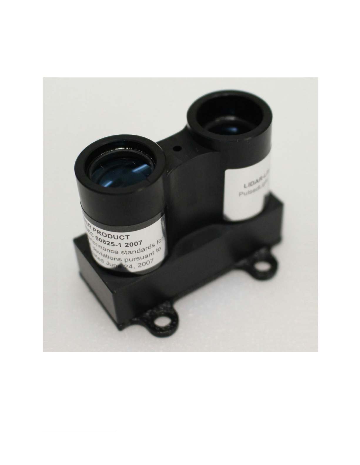
LaserSafety
LIDARLiteisalaserrangefinderthatemitslaserradiation.ThisLaserProductisdesignatedClass1during
allproceduresofoperation.Thismeansthatthelaserissafetolookatwiththeunaidedeye.However,itis
veryadvisabletoavoidlookingintothebeamandpowerthemoduleoffwhennotinuse.
NoregularmaintenanceisrequiredforLIDARLite.Intheeventthattheunitbecomesdamagedoris
inoperable,repairorserviceofLIDARLiteisonlytobehandledbyauthorized,factorytrainedtechnicians.
NoserviceofLIDARLitebytheuserisallowed.Attemptingtorepairorservicetheunitonyourowncan
resultindirectexposuretolaserradiationandtheriskofpermanenteyedamage.Forrepairorservice
pleasecontactPulsedLightdirectlyforareturnauthorization.
NousershouldmodifyLIDARLiteoroperateitwithoutitshousingoroptics.TheoperationofLIDARLite
withoutahousingandopticsormodificationofthehousingoropticsthatexposesthelasersourcemay
resultindirectexposuretolaserradiationandtheriskofpermanenteyedamage.Removalormodification
ofthediffuserinfrontofthelaseropticmayresultintheriskofpermanenteyedamage.
Caution–Useofcontrolsoradjustmentsorperformanceofproceduresotherthanthosespecifiedherein
mayresultinhazardousradiationexposure.PulsedLightisnotresponsibleforinjuriescausedthroughthe
improperuseoroperationofthisproduct.
LIDARLitev1“SilverLabel”Manual,Updated:08/13/15

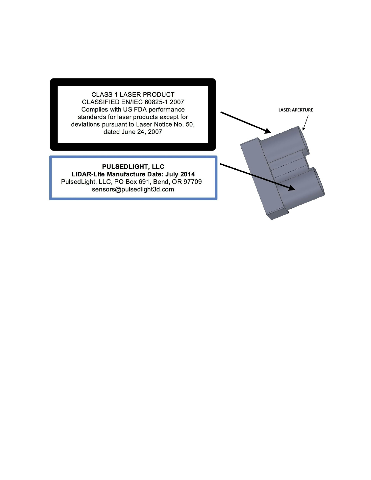
Class1LaserProduct
ThisLaserProductisdesignatedClass1duringallproceduresofoperation.
Parameters
LaserValue
Wavelength
905nm(nominal)
TotalLaserPowerPeak
1.3Watts
Modeofoperation
Pulsed(maxpulsetrain256
pulses)
PulseWidth
0.5µSec(50%dutyCycle)
PulseRepetitionFrequency
1020KHznominal
EnergyperPulse
<280nJ
BeamDiameteratlaseraperture
12mmx2mm
Divergence
4mRadianx2mRadian(Approx)
LIDARLitev1“SilverLabel”Manual,Updated:08/13/15

QuickStartGuide
Overview
1. MakePowerandI2CDataConnectionsasperJ1connectorpinoutdiagram.Pins2&3are
optionalconnectionsandnotrequired.
2. Initialization:ApplyPowertotheModule.Thesensoroperatesat4.755.5VDCNominal,Maximum
6VDC
3. Measurement:Writeregister0x00withvalue0x04(ThisperformsaDCstabilizationcycle,Signal
Acquisition,Dataprocessing).Refertothesection“I2CProtocolSummary”inthismanualformore
informationaboutI2CCommunications
4. PeriodicallypolltheunitandwaituntilanACKisreceived.Theunitrespondstoreadorwrite
requestswithaNACKwhenthesensorisbusyprocessingacommandorperforminga
measurement.(Optionally,waitapprox.20millisecondsafteracquisitionandthenproceedtoread
highandlowbytes)
5. Read:Register0x0f,returnstheupper8bitsofdistanceincm,register0x10,returnsthelower8
bitsofdistanceincm.(Optionallya2Bytereadstartingat0x8fcanbedone)
SampleCode
SamplecodeandwiringforLIDARLiteusinganArduinoandsomeotherpopularplatformscanbe
downloadedbyvisitinghttps://github.com/PulsedLight3D.
LIDARLitev1“SilverLabel”Manual,Updated:08/13/15
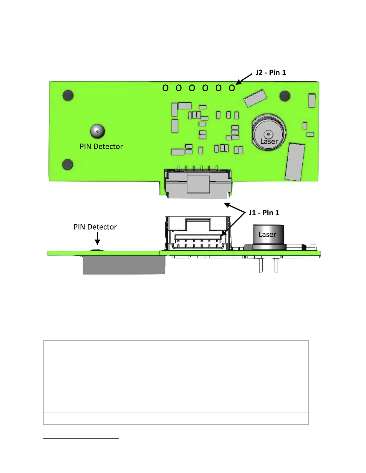
LIDARLiteSignal&PowerInterfaceDefinitions
J1Primaryinterface
BoardConnector:Molexpart#5023860670(DigiKeyPart#:WM3917CTND)
MatingConnector:Molex#5023800600PLUGHSG6POS(DigiKeyPart#:WM2271ND)
Pin
Description
PIN1
POWER_IN–4.755.5VDCNominal,Maximum6VDC.Peakcurrentdrawfromthis
input(whichoccursduringacquisitionperiod)istypically<100mAoveraduration
from4to20msdependingonreceivedsignalstrength.Unlessyouusepower
management,theunitwilldraw80mAbetweenacquisitiontimes.
PIN2
POWER_ENActivehigh,enablesoperationofthe3.3Vmicrocontrollerregulator.
Lowputsboardtosleep,draws<40μA.(Internal100Kpullup)
PIN3
ModeSelect–Providestrigger(highlowedge)PWMout(high)
LIDARLitev1“SilverLabel”Manual,Updated:08/13/15

PIN4
I2CClock(SCL)
PIN5
I2CData(SDA)
PIN6
Signal/powerground.
J2Secondarysignal/power.1”spacingMolexstylethroughhole
(FactoryOptionOnly)
Pin
Description
PIN1
LaserBypass520Vmax(nominallyconnectedtopin2throughinductorL8–
removedforexternalpower)
PIN2
POWER_IN–4.755.5VDCNominal,Maximum6VDC
PIN3
POWER_ENActivehigh
PIN4
Externalreferenceclockinput(FactoryOption–ConsultFactory)
PIN5
Signal/powerground.
PIN6
Detectorbias–upto25VexternalbiasforPIN,externalbiasinput200VforAPD
(consultfactory)
LIDARLitev1“SilverLabel”Manual,Updated:08/13/15

I2CProtocolSummary
LIDARLitehasa2wireI2Ccompatibleserialinterface(refertoI2CBusSpecification,Version2.1,January
2000,availablefromPhilipsSemiconductor).ItcanbeconnectedtoanI2Cbusasaslavedevice,under
thecontrolofanI2Cmasterdevice.Itsupportsstandard100kHzdatatransfermode.Supportisnot
providedfor10bitaddressing.
TheSensormodulehasa7bitslaveaddresswithadefaultvalueof0x62inhexadecimalnotation.The
effective8bitI2Caddressis:0xC4write,0xC5read.Theunitwillnotpresentlyrespondtoageneralcall.
TheI2Cserialbusprotocoloperatesasfollows:
1. Themasterinitiatesdatatransferbyestablishingastartcondition,whichiswhenahightolow
transitionontheSDAlineoccurswhileSCLishigh.Thefollowingbyteistheaddressbyte,which
consistsofthe7bitslaveaddressfollowedbyaread/writebitwithazerostateindicatingawrite
request.Awriteoperationisusedastheinitialstageofbothreadandwritetransfers.Iftheslave
addresscorrespondstothemodule’saddresstheunitrespondsbypullingSDAlowduringtheninth
clockpulse(thisistermedtheacknowledgebit).Atthisstage,allotherdevicesonthebusremain
idlewhiletheselecteddevicewaitsfordatatobewrittentoorreadfromitsshiftregister.
2. Dataistransmittedovertheserialbusinsequencesofnineclockpulses(eightdatabitsfollowedby
anacknowledgebit).ThetransitionsontheSDAlinemustoccurduringthelowperiodofSCLand
remainstableduringthehighperiodofSCL.
3. An8bitdatabytefollowingtheaddressloadstheI2Ccontrolregisterwiththeaddressofthefirst
controlregistertobereadalongwithflagsindicatingifautoincrementoftheaddressedcontrol
registerisdesiredwithsuccessivereadsorwrites;andifaccesstotheinternalmicroorexternal
correlationprocessorregisterspaceisrequested.Bitlocations5:0containthecontrolregister
addresswhilebit7enablestheautomaticincrementingofcontrolregisterwithsuccessivedata
blocks.Bitposition6selectscorrelationmemoryexternaltothemicrocontrollerifset.(Presentlyan
advancedfeature)
4. Ifareadoperationisrequested,astopbitisissuedbythemasteratthecompletionofthefirstdata
framefollowedbytheinitiationofanewstartcondition,slaveaddresswiththereadbitset(one
state).Thenewaddressbyteisfollowedbythereadingofoneormoredatabytessuccession.
Aftertheslavehasacknowledgedreceiptofavalidaddress,datareadoperationsproceedbythe
masterreleasingtheI2CdatalineSDAwithcontinuingclockingofSCL.Atthecompletionofthe
receiptofadatabyte,themastermuststrobetheacknowledgebitbeforecontinuingthereadcycle.
5. Forawriteoperationtoproceed,Step3isfollowedbyoneormore8bitdatablockswith
acknowledgesprovidedbytheslaveatthecompletionofeachsuccessfultransfer.Atthe
completionofthetransfercycleastopconditionisissuedbythemasterterminatingoperation.
Note:TheunitrespondstoreadorwriterequestswithaNACKwhenthesensorisbusyprocessinga
commandorperformingameasurement.ForproperoperationtheI2Cperipheraldriverneedstohandlethe
NACKconditionwithoutproducinganerrorcondition.
LIDARLitev1“SilverLabel”Manual,Updated:08/13/15


PCBDimensions
LIDARLitev1“SilverLabel”Manual,Updated:08/13/15

TechnologyandSystemHardwareOverview
Technology
PulsedLight’s“Timeofflight“distancemeasurementtechnologyisbasedontheprecisemeasurementofthe
timedelaybetweenthetransmissionofanopticalsignalanditsreception.Ourpatented,highaccuracy
measurementtechniqueenablesdistancemeasurementresolutiondownto1cmbythedigitizationand
averagingoftwosignals;areferencesignalfedfromthetransmitterpriortothedistancemeasurementand
areceivedsignalreflectedfromthetarget.Thetimedelaybetweenthesetwostoredsignalsisestimated
throughasignalprocessingapproachknownascorrelation,whicheffectivelyprovidesasignaturematch
betweenthesetwocloselyrelatedsignals.Ourcorrelationalgorithmaccuratelycalculatesthetimedelay,
whichistranslatedintodistancebasedontheknownspeedoflight.AbenefitofPulsedLight’sapproachis
theefficientaveragingoflowlevelsignalsenablingtheuseofrelativelylowpoweropticalsources,suchas
LEDsorVCSEL(VerticalCavitySurfaceEmitting)lasers,forshorterrangeapplicationsandincreased
rangecapabilitywhenusinghighpoweropticalsourcessuchaspulsedlaserdiodes.
SystemHardware
TheSingleBoardSensorprovidesdistanceandvelocitymeasurementsinanultrasmallformfactor.This
smallsizeistheresultofPulsedLight'sSystemOnChip(SoC)signalprocessingtechnologywhich,beyond
beingsmall,reducesthecomplexityandpowerconsumptionofsupportingcircuitry.Thesystemconsistsof
threekeyfunctionalities:
● ASignalProcessingCore(SPC)SystemonChipsolutionencapsulatingalltherequiredfunctionsin
supportofourproprietaryrangefindingsystemarchitecture.
● AnopticaltransmitterandreceivertiedtotheSPCemitandreceiveaproprietaryopticalsignal
patterngeneratedbytheSPC.
● PowerConditioningandI2Csignalfilteringandbuffering.
Pleasereferto“LIDARLiteBlockDiagram”forafulloverviewofthesystemarchitecture.
LIDARLitev1“SilverLabel”Manual,Updated:08/13/15

LIDARLiteBlockDiagram
SignalProcessingCore(SPC)
ThekeycomponentwithinthesystemisourSPCchipwhichimplementsPulsedLight'ssignalprocessing
algorithmsandprimarysystemarchitecture.TheSPCcontainsfourmajorsubsystems;
LIDARLitev1“SilverLabel”Manual,Updated:08/13/15

1. An8bitmicrocontrollerprovidessystemcontrolandcommunications.ItcontainsanI2Cslave
peripheral.
2. A500MHzsamplingclockandanassociatedsamplercapturethelogicstateoftheexternal
comparatorandconvertthedataintoaslowerspeed125MHzfourbitwordwhichissenttoa
correlationprocessor.
3. Acorrelationprocessorstorestheincomingsignalandperformsacorrelationoperationagainsta
storedsignalreferencewithopticalburstreceptionandstorestheresultinthecorrelationmemory
withdatapointsevery2ns.
4. Atransmitsignalgeneratorproducesanencodedsignalwaveformwithanoveralldurationof500ns
thatconsistsofavaryingintervalpatternofonesandzeroes.Theseoutgoingsignalpulsesoccurat
a20KHzrepetitionrateandbecomeeitherthereferencesignaloroutgoingsignalpulsedepending
onthestateofthetransmitter.
OpticalTransmitterandReceiver
Theopticaltransmitterandreceiverhavebeendesignedaroundtherequirementsofoursignalprocessing
algorithm.ThetransmitterproducesopticalpulseburstsusingsignalpatternsgeneratedbytheSPC.When
anopticalreferencesignalisdesired,aseparatereferencetransmitterisenabledanddrivenwiththesignal
patternusingareferencefedtotheopticalreceiver.Thereferencetransmitterhasbeendesignedtomatch
thedelayandsignalshapeproducedbythehigherpowersignaltransmitter.Thesignaltransmittercan
driveavarietyofopticalsourcesrangingfromhighspeedLEDs,higherpowerVCSELlaserormuchhigher
powerpulsedlaserdiodes.FortheLIDARLitemodule,thesignaltransmitdriverdrivesaT13/4plastic
packagedlaserdiodewithathreeamppeak,50%averagedutycyclemodulationoveraburstdurationof
500ns.Thedriverhasacapabilitytodrivesourcesatupto6AusinganexternalDCpowersupply.
Parameter
Transmitterspecification
Bandwidth
50MHz,onoffmodulation,arbitrarypattern
BurstTime/rate
500ns/20KHz
Typology
Highsidecurrentsource(programmable),lowsidedifferentialcurrentsteering
ReferenceChannel
1Apeak(nominalsetting)
SignalChannel
3Apeak(nominalsetting)
TransmitPower
Control16stepseachChannel
Rise/fall
4ns
ThereceiverincorporatesastateoftheartlownoisepreamplifierthatiscoupledtoeitheraPINphotodiode
or,optionally,anavalanchephotodiode(APD).WhenusingthehigherperformanceAPD,anexternal
regulatedhighvoltagebiasvoltageisneeded.TheAPDisusedtoincreasedsystemsensitivityallowing
eitherincreasedoperatingrangeorreducedmeasurementtimes.Beforereachingthehighspeeddigital
LIDARLitev1“SilverLabel”Manual,Updated:08/13/15

comparator,specializedanalogfilteringshapesthereturnsignaloriginatingfromtheoutputofthe
preamplifier.
Parameter
Receiverspecification
Bandwidth
50MHz
Detector
PINdiode,500µmby500µm,1.5pF,1.8mmdiameter
lens
VirtualDetectorsize
1mm–roughly2Xmagnificationofthepackagelens
DetectorBiasVoltage
8VDCnominal.External
PreampNoiseFloor
1pA/Hz2
TransimpedanceGain
40Kohm
NoiseEquivalentPower
12nWrms
BackgroundLight
LIDARLitehasbeendesignedtooperateeffectivelyunderavarietyofindoorandbrightoutdoorsolar
backgroundlightingconditions.Theinternalopticalabsorptionfilterincombinationwiththedetectorspectral
responseprovidesatransmissionbandfrom800nmto1000nm.Outdoors,thisSpectralwindowallows
roughly14%ofthetotalsolarIrradiancetopasstothedetector.Assumingasolarconstantofroughly1KW
permeter²,andafullreceiverfieldofviewoftwodegrees,wegetthefollowingcalculatedDCsolarcurrent
anddetectorshotnoise:
Brightsolaropticalbackground=6µW
SolarDCcurrent=(6e6W)(.6A/W)=3.6e6A
Shotnoise=((3.6e6A)(2)(1.6e19)(1/Hz))1/2=1pA/Hz1/2
Underthebrightsolarconditionsandhighlyreflectivediffusebackgroundcalculatedabove,theequivalent
receiverinputnoisefloorof1pA/Hzwouldincreasebyafactorof1.4resultinginaslightreductionin
maximumrange.A20nmspectralwidthnarrowbandopticalfilterisavailableasafactoryoptionand
resultsina10foldreductioninsolarDCcurrentora(10)1/2=3folddecreaseintheresultingnoise.The
narrowbandfilterisofmostbenefitinapplicationswherespecular,“mirrorlike”reflectivesurfaces,are
present.
LIDARLitev1“SilverLabel”Manual,Updated:08/13/15

PowerConditioning
MultiplevoltagereferencesarerequiredbyvariousfunctionsontheLIDARLiteboard.ThestandardPIN
detectorrequiresaDCbiasvoltageofroughly8Vgeneratedbyaninternalvoltagemultiplier.Theuseof
optionalAPDdetectorrequiresatemperaturedependentbiasfrom100Vupto240Vdependingonthe
selecteddetector.Thisvoltagebiasisvariedbasedonthetemperaturecompensationcoefficientandis
appliedthroughtheexternaldetectorbiasinputpin.Afactorymodificationisrequiredtoallowexternal
applicationofdetectorvoltagesabove30VDC.A3.7Vpowersupplyisusedbythereceivercircuitryand
isenabledbytheSPC.Transmittercircuitrytypicallyusesthe5Vnominalsupplyvoltage.Bydefaultthe
powersupplypiniscoupledtothe5Vinputthroughanisolationinductor.Anenablepinallowstheinternal
3.3Vregulatortobedisabledallowingverylowpowerconsumptionundershutdownconditions.
LIDARLitev1“SilverLabel”Manual,Updated:08/13/15

OperationalOverview
OperationofLIDARLitecanbeseparatedintotwophases;initializationandtriggeredacquisitionsas
initiatedbytheuser.
Duringinitializationthemicrocontrollergoesthroughaselftestsequencefollowedbyinitializationofthe
internalcontrolregisterswithdefaultvalues.Internalcontrolregisterscanbecustomizedbytheuser
throughtheI2Cinterfaceafterinitialization.Aftertheinternalcontrolregistersareinitializedtheprocessor
goesintosleepstatereducingoverallpowerconsumptiontounder10mA.Initiationofausercommand,
throughexternaltriggerorI2Ccommand,awakesaprocessorallowingsubsequentoperation.
TheinputofacommandthroughtheI2Cinterfacesmayinitiateanacquisitionoranoperationtomonitoror
modifysystemparameters.Intheeventofanacquisitionrequest,thesystemmustfirstpowerupand
initializetheexternalfunctionssuchastheSPCandtransmit/receivecircuitry.Acquisitionbeginswiththe
transmissionofareferenceburstfollowedbyasignalburst.Thesesignalburstsoccuroverintervalsof
roughly50100µsdependingonthelengthoftheselectedcorrelationrecord.Thesesignalburstsare
repeateduntilthemaximumnumberofacquisitionshavebeenreached,asdefinedinthedefaultoruser
settingsorasufficientnumberofacquisitionshavebeenperformedtoachieveamaximumsignalstrength
level.Atthecompletionoftherequirednumberofacquisitioncycles,thecorrelationresultsareprocessed
tocalculatetheeffectivetimedelayofthereferenceandreturnwithinthecorrelationrecords.Thetotal
acquisitiontimeforthereferenceandsignalacquisitionsistypicallybetween5and20msdependingonthe
desirednumberofintegratedpulsesandthelengthofthecorrelationrecord.Theacquisitiontimeplusthe
required1msectodownloadmeasurementparametersestablisharoughly100Hzmaximummeasurement
rate.
ModeControlPin
Abidirectionalcontrolandstatuspinprovidesameanstotriggeracquisitionsandreturnthemeasured
distanceviaPulseWidthModulation[PWM]withouthavingtousetheI2Cinterface.
Thepindriverintheprocessorhasaninternalcurrentsourcepullupofroughly50uAwiththedriveroutput
coupledtotheuserpinthroughaprotectiondiodeallowingonlysourcingcurrentintothepin.Alowgoing
transitiononthemodecontrolpinwilltriggerasinglemeasurement,andthepinwillbeactivelypulledhigh
withapulsewidthproportionaltodistance.A1Kto10Kohmterminationresistancewillsolidlypullthepin
lowtotriggeranacquisitionstatewhileallowingthepintostillbepulledhighduringthePWMoutputpulse.
Thepulsewidthfollowsa10usec/cmrelationshiptothemeasureddistanceor1msecpermeter.
Asimpletriggeringmethodusingastandardmicrocontrollerinterfaceusesa1Kohmresistorinserieswith
anoutputpintopullthemodepinlowinitiatingameasurementwithasecondportpinusedtomonitorthe
lowtohighoutputpulsewidth.Ifthepinisheldlow,theacquisitionprocesswillrepeatindefinitely
producingavariablefrequencyoutputproportionaltodistance.
LIDARLitev1“SilverLabel”Manual,Updated:08/13/15

AcquisitionSettings
Signalacquisitionparameterscanbeeasilychangedtotradeoffsystemperformanceparameters.Ifahigh
measurementrateisrequired,thenthemaximumsignalintegrationtimecanbereducedtodecrease
measurementtimesattheexpenseofsomewhatreducedsensitivityandmaximumrange.Opticaltransmit
powercanbeincreasedbythesettingloadedintotheLaserPowerRegister.Highpulsepowermayneedto
becompensatedwithanincreasedspacingbetweenpulseburststomaintainanacceptablelaserdutycycle
basedonthermalderatingrequirements.Ifthelengthofthecorrelationrecordisincreasedtoallowfor
longerrangemeasurements,increasedprocessingtimewilldecreasethemeasurementrate.
Keycontrolregistersimpactingacquisitions:
Internalregisterspace
Register
Description
control_reg[2]
Maximumacquisitioncountsetsthemaximumnumberofacquisitioncycles
withamaximumvalueof255.Inmostcasesanacquisitionof128is
adequate.
control_reg[3]
Correlationrecordlengthestablishestheportionofcorrelationmemory
allocatedtothereturnsignal.Thevalueisbrokenintoupperandlower
LIDARLitev1“SilverLabel”Manual,Updated:08/13/15
Table of contents
Other Garmin Measuring Instrument manuals

Garmin
Garmin LIDAR-LITE V3HP User manual

Garmin
Garmin Approach Z82 User manual

Garmin
Garmin Approach Z82 User manual

Garmin
Garmin GI 275 User manual

Garmin
Garmin GHP 10 Marine Autopilot System Service manual

Garmin
Garmin Approach Z80 User manual

Garmin
Garmin HRM-Swim User manual

Garmin
Garmin A03610 User manual

Garmin
Garmin VECTOR 3 User manual

Garmin
Garmin TruSwing User manual


