Favero Radio-Spark-115 User manual

FUNZIONAMENTO
INSTALLAZIONE
SENSIBILITÁ
Questa scheda viene installata all'interno di un'apparecchiatura
per individuare disturbi elettrici generati nelle vicinanze da
trasmettitori radio e/o scariche elettriche ed interrompe immediata-
mente l'alimentazione segnalando l'allarme.
Essa interviene nei tentativi di manomissioni dovuti a:
: la presenza di un elevato segnale di
radiofrequenza provoca l'interruzione dell'alimentazione e
la segnalazione di allarme con un suono intermittente (1 bip
ogni 0,5s) per . La gamma delle frequenze rilevate è
molto ampia e copre tutte quelle che sono state riscontrate
essere pericolose.
:
in questo caso l’allarme è segnalato da un suono intermittente
veloce.
: l'accensione avviene dopo 5
secondi che l'interruttore di accensione è stabile nella posizione
di acceso.
La scheda Radio-Spark deve essere installata all'interno
dell'apparecchiatura da proteggere, dal produttore di quest'ultima.
È bene che l'apparecchiatura disponga di un filtro di rete all'entrata
dei 115V per evitare che forti disturbi provenienti dall'esterno
provochino allarmi indesiderati.
Eseguire i collegamenti come indicato dallo schema in figura.
I 2 fili di alimentazione , provenienti dall'interruttore generale
dell'apparecchiatura (dopo il filtro di rete), devono entrare nei
morsetti V -A e V -B della scheda Radio-Spark. Tale alimentazio-
ne, se non interrotta a causa di un disturbo elettrico, fuoriesce dai
morsetti V -A e V -B.
Ai morsetti 5 e 7 del Radio-Spark si devono collegare 2 spezzoni
di filo isolato che hanno la funzione di antenne di
ricezione dei disturbi. Utilizzare qualsiasi filo isolato, con sezione
di 0,5~1mm .
: dovrebbe passare vicino alle zone
sensibili alle scariche oppure attorcigliato lungo i fili del
cablaggio dell'apparecchiatura. Il filo può essere allungato nel
caso sia necessario ottenere una maggiore sensibilità.
: la posizione ideale del filo è diritta e
lontana da altri fili o strutture metalliche. Sulle apparecchiature
di piccole dimensioni può comunque essere posizionata
assieme all’Antenna-scariche.
Può essere regolata sia la sensibilità alle scariche (Sens.SPARK)
che quella alla radiofrequenza (Sens.RF) (vedi figura). Girare il
rispettivo trimmer in senso orario (+) per aumentare la sensibilità e
viceversa (-) per diminuirla. Se la regolazione non è sufficiente, si
può allungare l'antenna per aumentare la sensibilità oppure
accorciarla per diminuirla.
1)
2)
3)
Trasmettitori radio
Scariche elettriche (di accendigas, accendini piezolettrici, ecc.)
Ripetuti spegnimenti-accensioni
Antenna Scariche (spark)
Antenna RadioFrequenza
Collegamento dell'alimentazione da interrompere
Collegamento antenne
lunghi circa 50cm
IN IN
OUT OUT
2
115V
115V
5 secondi
115V
Sensibilità alla RadioFrequenza (Sens.RF)
Sensibilità alle scariche (Sens.SPARK)
: in mancanza di
strumentazione di prova si consiglia di lasciare il trimmer nella
posizione centrale. Per una verifica dell’efficacia dell’allarme
radio si consiglia l’aquisto di un comune ricetrasmettitore
portatile 27MHz - 5Watt. L’allarme deve avvenire quando si
trasmette (con batteria carica) a 0,5~1m dall'apparecchiatura da
proteggere.
: lasciando il trimmer
nella posizione centrale si ottiene un intervento efficace per la
maggior parte delle apparecchiature da proteggere.
Si consiglia di aumentarla (+) solo se si riscontra una scheda
particolarmente suscettibile alle scariche, e di diminuirla (-) se
avvengono spegnimenti ingiustificati dell'apparecchiatura, che
potrebbero verificarsi in locali con elevati disturbi sulla rete di
alimentazione.
Sul Radio-Spark è possibile abilitare la funzione Antidisturbo-
Saltuario, ponticellando, con l'uso di un saldatore, il punto indicato
con JP5 sullo schedino.
Tale funzione evita lo spegnimento dell'apparecchiatura se
avviene una saltuaria scarica elettrostatica (simile a quella che
spesso si prova scendendo dall'auto) oppure un elevato disturbo
di rete.
Se la funzione Antidisturbo-Saltuario è abilitata (ponticello chiuso),
lo spegnimento dell'apparecchiatura avviene solo se la scarica (o il
forte disturbo di rete) avviene entro un minuto dalla scarica
precedente, altrimenti la scarica provoca solamente la segnalazio-
ne sonora.
Si consiglia di abilitare tale funzione solo se l'apparecchiatura è
installata in locali con pavimentazione in materiale sintetico, tipo
moquette (dove possono manifestarsi cariche elettrostatiche), o
dove avvengono elevati e frequenti disturbi di rete.
Massima corrente sui morsetti V -A/B e V -A/B: 10A
Alimentazione della scheda Radio-Spark:
utilizza la tensione presente ai morsetti V -A/B:
max.
Tempo intervento tipico: 5ms (= tempo diseccitazione relè).
Intensità sonora del buzzer: 105dB a 30cm
Dimensioni e peso: 104 x 51 x H42mm - 0,24kg
Funzione “ANTIDISTURBO SALTUARIO”
DATI TECNICI
IN OUT
IN
115Vac, 60mA
Controllore di manomissioni dovute a trasmettitori di radiofrequenza e a scariche
elettriche (di accendigas, accendini piezoelettrici, ecc.)
R S 115adio- parK-
(Art.A4-115)
L
N
Relè
ingresso
115V
L
N
Ingresso
alimentazione
Uscita alimentazione.
(viene interrotta dal
relè quando avviene
il disturbo)
uscita
115V
V AIN
V A
OUT
V BIN
V BOUT
Ant.
RF
Antenna Spark
Antenna RF
+
-
Spark
Sens. SPARK
Sensibilità alle scariche elettriche
5
6
7
RF
Sens. RF
Sensibilità alla Radio Frequenza
+
-
JP5
Favero Electronic Design A4-115-M02-IE Radio-Spark-115Pag. 1 / 2

OPERATION
INSTALLATION
SENSITIVITY
This board is placed inside the device to detect electrical distur-
bances generated by nearby radio transmitters and/or electrical
discharges and it immediately interrupts the power supply 115V by
sounding an alarm.
It operates on attempted tampering due to:
: in the presence of a high level of radio
frequency, the Radio-Spark causes the interruption of 115V
power and activates a signal alarm with a beeping sound (1
beep every 0.5s) for 5 seconds. The range of the radio
frequencies detected is vast and covers all those that have
been found to be dangerous.
:
in this case the alarm is signalled by a fast intermittent sound.
: the device is powered 5 seconds
after the switch is stable in the “on” position.
For safe use of the device, the Radio-spark has to be placed inside
by the manufacturer.
It is advisable that the device is provided with a line filter placed in
the 115V entry so as to avoid strong disturbances coming from the
outside causing undesired alarms.
Please, make connections as indicated by the instructions
given on the schematic.
The two 115V power wires coming from the device general switch
(after the line filter) have to enter into the terminal blocks V -A and
V -B of the Radio-Spark board. Such power, if not interrupted by
an electrical disturbance, comes out from the V -A and V -B
terminal blocks.
To the terminal block 5 and 7 of the Radio-Spark, two 50 cm long
insulated wires that work as antennae for capturing disturbances
have to be connected. You can use any insulated wire with a cross
section of 0,5~1mm .
: it should pass close to the dis-
charge-sensitive areas or it should be twisted around the wires
of the cabling of the device. The wire can be lengthened, if
necessary in order to achieve a greater sensitivity.
: the ideal position of the wire is
straight and away from other wires or metal structures. As for
small devices, it can be positioned together with the ESD
antenna.
It is possible to adjust either the sensitivity to electrical discharge
(SPARK Sens.) or to radio-frequency shocks (RF Sens.) (see
figure). Turn the respective trimmer clockwise (+) to increase the
sensitivity and viceversa to (-) decrease it. If this adjustment is not
sufficient you can lengthen the antenna to increase the sensitivity
or you can shorten it to decrease it.
: in case the test
1)
2)
3)
Radio transmitters
Electrical discharge (of gas lighters, piezoelectrical lighters, etc.)
Repeated power on and off
ESD Antenna (spark) wire
Radio-frequency antenna wire
Sensitivity to Radio-frequency (RF Sens.)
Connection to the power supply that has to be interrupted
Antennae Connection
IN
IN
OUT OUT
2
per
instrumentation is not available it is advised that you put the
trimmer into the centre position. For the verification of the
effectiveness of the radio alarm it is advised to buy a common
portable transceiver 27MHz - 5Watt. The alarm goes when
transmitting (with a completely charged battery) at 0,5~1m
distance from the device that has to be protected.
: by leaving the trimmer
in the centre position you achieve a maximum effect for most of
the devices you wish to protect.
It is advised to increase it (+) only when you happen to have a
board particularly sensitive to discharges, and to decrease it (-)
when you notice that there are often power cut-offs of the device
for no reason, which could happen in places with high distur-
bances on the power grid.
It is possible to activate the function Occasional-antidisturbance on
the Radio-spark, by jumping the JP5 point indicated on the board
by using a soldering iron.
Such function avoids the power off of the device in case of
occasional electrostatic discharge (similar to the one you experi-
ence by getting out of a car) or a strong disturbance.
If the Occasional-anti-disturbance function is activated (closed
jumper) the power off of the devise happens only if the discharge
(or the strong disturbance) is due within a minute from the
previous discharge, otherwise the discharge causes only a
sounding signal.
It is advised to activate that function only if the device is placed in
rooms with synthetic flooring, such as carpet (where electrostatic
discharges may happen) or where there are often distur-
bances.
Max current allowed on terminal blocks V -A/B and V -A/B: 10A
Power to Radio-spark board:
it uses the voltage which is on V -A/B terminal
blocks: 115Vac, 60mA max.
Typical operation time: 5ms (= relay time).
Buzzer sound strength: 105dB at 30cm
Dimensions and weight: 104 x 51 x H42mm - 0.24kg
Sensitivity to discharges (SPARK Sens.)
“OCCASIONAL ANTIDISTURBANCE” function
TECHNICAL INFORMATION
IN OUT
IN
off
grid
grid
grid
release
Controlling device for tampering due to radio frequency transmitters and to electrical
discharges (of gas lighters, piezoelectric lighters, etc...).
L
N
Relè
entry
115V
L
N
Power entry
Power exit
(it is interrupted by
the relay when the
disturbance occurs).
exit
115V
V AIN
V AOUT
V BIN
V BOUT
Ant.
RF
Antenna Spark
Antenna RF
+
-
Spark
SPARK Sens.
Sensitivity to electrical discharges
5
6
7
RF
RF Sens.
Sensitivity to radio frequency
+
-
JP5
R S 115adio- parK-
(Art.A4-115)
Favero Electronic Design A4-115-M02-IE Radio-Spark-115Pag. 2 / 2
This manual suits for next models
1
Table of contents
Languages:
Popular Control Unit manuals by other brands
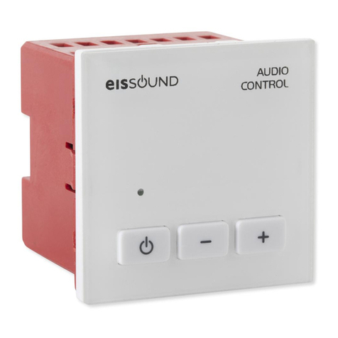
EisSound
EisSound Audio Control Unit Installation & user manual

ARAG
ARAG IBX100 4679004 Directions for installation, use and maintenance
Linear Technology
Linear Technology DC1930A Demo Manual

Carel
Carel FLSTDMFC0A manual
Jung Pumpen
Jung Pumpen BASICLOGO instruction manual

Dixon Bayco
Dixon Bayco 2182 Maintenance & Operating Instructions

Belden
Belden Grass Valley HCO-1822 Guide to installation and operation
Danfoss
Danfoss ICM 20 Installation, programming, and troubleshooting manual
Sierra Wireless
Sierra Wireless AirPrime series Hardware integration guide
One Lux
One Lux OMNI-LED DST OL12/2/M3/DST manual
BENDIX
BENDIX TP-3 TRACTOR PROTECTION VALVE manual
Domino
Domino XM2 Directions for the use

