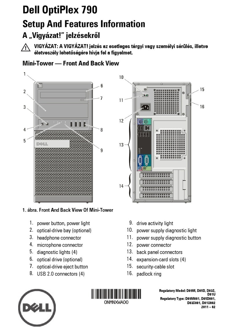
Faytech Capacitive Touch PC User manual

INSTRUCTION MANUAL
Capacitive
Touch PC
Apollo Lake

English - 2
Copyright © 2018-2020 faytech AG

Table of contents
Foreword 4
Notes of Documentation 4
Disclaimer 4
Copyright 4
State of Delivery 4
Explanation of the safety symbols 5
Basic security measures 6
Duty of care for the operator 7
Requirements for the operating personnel 7
General warning 7
Warranty 8
Product description 10
Appropriate use 10
Interfaces 11
Status LEDs 13
Scope of delivery 13
Installation instructions 14
Transportation 14
Unpacking 14
Mounting Options 15
Connecting the Device 17
Operating instructions 18
Initial power-up and driver installation 18
BIOS Settings 18
Troubleshooting 19
FAQs 19
Service and Support 20
Service 20
Contact 20
Appendix 21
CE Declaration of Conformity 21
English - 3
Table of contents

Foreword
Foreword
This description is intended exclusively for trained specialists in controlling and automation technology
who are familiar with the applicable national standards. For installation and commissioning of the
components it is absolutely necessary to observe the following notes and explanations. The qualified
personnel must ensure that the application or use of the described products meets all safety
requirements, including all applicable laws, regulations, provisions and standards.
Disclaimer
This documentation has been carefully prepared. However, the products described are subject to
continuous further development. Therefore, the documentation is not always completely checked for
compliance with the described performance data, standards or other features. If it contains technical or
editorial errors, we reserve the right to make changes at any time and without notice. The information,
illustrations and descriptions in this documentation do not constitute grounds for claims for changes to
products already supplied.
Copyright
© faytech AG.
Passing on and reproduction of this document, use and communication of its contents are prohibited
unless expressly permitted. All rights reserved in case of patent, utility model or design patent
registration.
State of delivery
All components are delivered in specific hardware and software configurations depending on the
application requirements. Changes to the hardware or software configuration, which go beyond the
documented possibilities are not permitted and result in the exclusion of liability of faytech AG.
Notes on documentation
English - 4

Foreword
Explanation of the safety symbols
The following safety symbols are used in these operating instructions. These symbols are primarily
intended to draw the reader's attention to the text of the adjacent safety instructions.
Acute danger of injury!
If the safety instruction next to this symbol is not observed, there is an
immediate danger to life and health of persons.
DANGER
Caution Risk of injury!
If the safety instruction next to this symbol is not observed, there is a
danger to life and health of persons.
WARNING
Injury to persons!
If the safety instruction next to this symbol is not observed, persons may be
injured.
CAUTION
damage to the environment or equipment
If the note next to this symbol is not observed, the environment or
equipment may be damaged.
Attention
Tip or pointer
This symbol indicates information that contributes to better understanding.
Note
English - 5

Foreword
English - 6
Basic security measures
Before the Touch PC may be switched off, the running software must be closed as usual. Otherwise
data on the hard disk may be lost. Please read the section Switching the Touch PC on and off.
Attention
Switch off all system components, then disconnect the fieldbus
Before opening the Touch PC housing and whenever the Touch PC is not
used for control purposes, for example during the functional test after a
repair, all system parts must first be switched off and then the Touch PC
must be disconnected from the system.
Switched off system parts must be secured against being switched on
again.
Attention
Do not replace any parts when under voltage
When installing and removing components, the supply voltage must be
switched off.
Damage can occur during installation in the Touch PC:
• If metal objects such as screws or tools are placed in
the circuit boards.
• If PC internal connection cables are pulled off
or plugged in during operation.
• If plug-in cards are removed or inserted when the PC is
switched on.

English - 7
Foreword
Duty of care for the operator
The operator must ensure that:
• The Touch PC is only used for its intended purpose (see chapter Product Description).
• The Touch PC is only operated in a faultless, fully functional condition.
• The operating manual is always available in a legible condition and complete at the place of use
of the Touch PC.
• Only sufficiently qualified and authorized personnel operate, maintain and repair the Touch PC.
• This personnel is regularly instructed in all applicable questions of occupational safety and
environmental protection, and the operating manual and in particular the information contained
therein contained in the safety instructions.
• All safety and warning notices attached to the Touch-PC are not removed and stay legible.
Depending on the type of machine and system in which the touch PC is used, there are national
regulations for the control of such machines and systems which the operator must comply with. These
regulations regulate, among other things, the intervals at which the controller must be checked.
The operator must arrange for this inspection within a certain period of time.
In the event of faults on the Touch PC, the list in the Troubleshooting section can be used to
determine which measures should be taken.
Every user of the touch PC must have read this operating manual.
Every user must be familiar with all the functions of the software installed on the PC accessible to
him/her.
Only qualified personnel may open the housing of the Touch PC
The operator must ensure that only trained electrical specialists open the
housing of the Industrial PC. In this case the warranty will become invalid.
Attention
Requirements for the operating personnel
General warning
If you notice a burning smell or the device is making noise, disconnect it from the power supply
immediately.
Cleaning
To clean the device, switch it off and use a dry, soft cloth with light pressure.
Note

Foreword
Warranty
faytech devices are produced following the most modern production and test
processes. Carefully selected components and accurate production ensure reliable
operation and long life. faytech warrants to the original purchaser that each faytech
display delivered shall be free from defects in material or workmanship at time of
shipment, and that each such module delivered will meet the published specifications
for a period of 24 months as measured from the date of original shipment. faytech's
obligation under the Warranty contained herein is limited to the repair or replacement
of any faytech touch monitor that does not meet the specifications, provided that said
product is returned to faytech, transportation charges pre-paid, and provided that
upon faytech's examination, the product, when tested within the specified ratings and
in accordance with good engineering practice, does not meet the specifications as
defined. THIS WARRANTY IS IN LIEU OF ALL OTHER WARRANTIES, EXPRESSED
OR IMPLIED, INCLUDING WITHOUT LIMITATION THE WARRANTY OF
MERCHANTABILITY AND THE WARRANTY OF FITNESS FOR A PARTICULAR
PURPOSE.
All claims under warranty must be made promptly after occurrence of circumstances
giving rise thereto and must be received within the applicable warranty period by
faytech or its authorized representative. Such claims should include the Product type
and serial numbers and a full description of the circumstances giving rise to the claim.
Before any Products are returned for repair and/or adjustment, written authorization
from faytech or its authorized representative for the return and instructions as to how
and where these Products should be shipped must be obtained. Any product returned
to faytech for examination shall be sent prepaid via the means of transportation
indicated as acceptable by faytech. faytech reserves the right to reject any warranty
claim not promptly reported and any warranty claim on any item that has been altered
or has been shipped by non-acceptable means of transportation. When any Product
is returned for examination and inspection, or for any other reason, Customer will be
responsible for all damage resulting from improper packing or handling and for loss in
transit, notwithstanding any defect or nonconformity in the Product. In all cases
faytech has sole responsibility for determining the cause and nature of failure, and
faytech's determination with regard thereto shall be final. If it is found that faytech's
Product has been returned without cause and is still serviceable, Customer will be
notified and the Product returned at Customer's expense. In addition, a charge for
testing and examination may, in faytech's sole discretion, be made on Products so
returned.
English - 8

English - 9
Foreword
SELLER'S LIABILITY FOR DAMAGES SHALL NOT EXCEED THE PAYMENT, IF ANY,
RECEIVED BY SELLER FOR THE UNIT OF PRODUCT OR SERVICE FURNISHED
OR TO BE FURNISHED AS THE CASE MAY BE WHICH IS THE SUBJECT OF CLAIM
OR DISPUTE. IN NO EVENT SHALL SELLER BE LIABLE FOR INCIDENTAL,
CONSEQUENTIAL OR SPECIAL DAMAGES. LIABILITY TO THIRD PARTIES, FOR
BODILY INJURY INCLUDING DEATH, RESULTING FROM SELLER'S
PERFORMANCE SHALL BE DETERMINED IN ACCORDANCE WITH APPLICABLE
LAW AND THE TOTAL LIABILITY LIMITATION STATED ABOVE SHALL NOT BE
CONSTRUED AS A LIMITATION ON SELLER FOR DAMAGES FOR ANY SUCH
BODILY INJURY, INCLUDING DEATH.
WARRANTY FOR ITEMS REPLACED UNDER WARRANTY Whenever a failed
module is replaced under Warranty, the greater of the balance of the original Warranty
Period or 90 days will constitute the remaining warranty period. The replaced unit
does not carry a new Warranty.
LIFE SUPPORT POLICY “WARNING: DO NOT USE IN LIFE SUPPORT” SELLER'S
PRODUCTS ARE NOT AUTHORIZED FOR USE AS CRITICAL COMPONENTS IN
LIFE SUPPORT DEVICES OR SYSTEMS WITHOUT THE EXPRESS PRIOR
WRITTEN APPROVAL OF THE CEO OF FAYTECH. As used herein, “Life Support
Devices or Systems” are devices which support or sustain life and whose failure to
perform when properly used in accordance with instructions for use provided in the
labeling can be reasonably expected to result in a significant injury to the user. A
“Critical Component” is any component in a life support device or system whose
failure to perform can be reasonably expected to cause the failure of the life support
device or system or to affect its safety or effectiveness.
If your device does have a defect within the warranty period, please contact faytech
directly. The warranty period is 24 months from the date of purchase under the
following conditions:
All warranties are void if the unit has been opened or disassembled without
faytech's prior approval.
Damage caused by improper handling or operation, by incorrect installation or
storage, through improper connections, as well as due to force majeure or other
external influences are not covered by the warranty.
For warranty claim, we reserve the right to replace the defective components or to
exchange the device.
Exchanged components or devices become the property of faytech.
Claims for damages are excluded in so far as they are not based on intent or gross
negligence of the manufacturer.
After expiration of the warranty period, warranty claims can no longer be pursued.
Any warranty claim must be accompanied by proof of purchase (receipt or invoice).
•
•
•
•
•
•
•

Product description
English - 10
Product description
Appropriate use
The faytech Capacitive Touch PC series are used in many different application areas (in industrial or
retail applications).
The heart of the capacitive touch PC series is the Apollo Lake industrial mainboard, driven by
N4200
an Intel®Pentium®N4200 QuadCore processor with up to 2.50 GHz frequency, 4G RAM, 128G SSD
and Intel®'s HD graphics chipset, Full HD support, Direct X 11.1 and OpenGL 4.0.
Front of the
15" Capacitive Touch PC

Product description
Right side of the
Capacitive Touch PC
Interfaces
English - 11
Interfaces of the Capacitive Touch PC
Power supply
The power supply of the Touch PC is established via the socket (1). The DC-In input (screwable) is 12V.
Network connection
The RJ-45 socket (2, 3) enables the Touch PC to be connected to a 10/100/1000 BASE-T network.
The antenna connector (4) of the Touch PC enables the connection via W-LAN with the supplied
antenna. Frequency band: 2.4GHz, Max. Transmission power: 2mW (with supplied antenna) / 6.3mW
(maximum with any antenna).
USB interfaces
The four USB interfaces (5, 6) are used to connect peripheral devices with USB connection. The USB
3.0 standard (5) and USB 2.0 standard (6) are supported.
DP (DisplayPort)
The DP connector (7) is for transmitting the video signal.
HDMI (High-Definition Multimedia Interface)
The HDMI terminal (8) is for transmitting the video signal.
RS232 / 485, COM1
The touch PC has a serial interface COM1 (9) of type RS232 / RS485, adjustable in the BIOS.

English - 12
Product description
On / Off switch
With the button (10) the touch PC can be switched on and off.
RS232 / 485, COM2
The touch PC has a serial interface COM2 (11) of type RS232 / RS485, adjustable in the BIOS.
RS232 / 485, COM3 & 4 (3-PIN)
The touch PC has a serial interface COM3 (12, 13) of type RS232 / RS485, adjustable in the BIOS.
Assigned pins and switching options can be found above.
DIO / GPIO (General-Purpose Input/Output)
The GPIO (14) is an RJ45 connector and has a total of 8 pins, as illustrated above.
Audio and microphone connection
The audio and microphone connection (15, 16) has a diameter of 3.5 mm and is used for transmitting
audio signals.
S/PDIF & TOSLINK (Sony/Philips Digital Interface)
The S/PDIF connector (17, 18) is for a unidirectional, self-synchronizing and serial interface for
electrical or optical transmission of digital stereo or multi-channel audio signals.
SSD Module Slot
The SSD slot (19) has a 2.5" exchangeable SSD.
Left side of the
Capacitive Touch PC
8 7 6 5 4 3 2 1
1.GPIO80
2.GPIO82
3.GPIO84
4.GPIO86
5.GPIO81
6.GPIO83
7.GPIO85
8.GPIO87
1 2 3 4
RS485
K2
RS485
P17
1.GND
2.GND
3.TX3/4
4.RX3/4
K2 P17
1 2 3 4
1.GND
2.GND
3.B/-
4.A/+
COM3
/COM4
COM3
/COM4
RS485 RS485
COM3
/COM4
COM3
/COM4
Standard Interne Switch
für COM3 / COM4
Change COM3-Switch
to RS485

Status LEDs
Moving or cleaning the device
Make sure that you only clean or move the device when the LED light is off.
Attention
No LED
There is no power supply.
Green LED
The touch PC is switched on.
Red LED
The Touch PC is connected to a power source, but it is currently switched off.
Scope of delivery
Manual
Power supply unit
The supplied power supply unit (1) has a screwable connection. The power supply is 100-240V AC
50-60 Hz 1.5A.
W-LAN antenna
The supplied W-LAN antenna (2) can be screwed onto the W-LAN connector to connect the touch PC
to a network (Internet).
Frequency band: 2.4GHz / Max. Transmission power: 2mW
Brief instructions
This quick guide (3) contains the most important information about the Touch PC.
Standard version
This standard stand (4) is included in the scope of delivery for the 13.3 - 27" devices. Can easily be
screwed on the backside with VESA 75 or VESA 100 holes.
English - 13
Product description

Installation instructions
Transportation
Despite the robust design, the built-in components are sensitive to strong vibrations and shocks.
Therefore, protect your touch PC from high mechanical stress during transport. Use the original
packaging for shipping.
Unpacking
Proceed as follows when unpacking the device:
1. Remove the packaging.
2. Do not throw away the original packaging. Keep it for re-transport.
3. Check the delivery for completeness based on your order.
4. Please keep the documents supplied with the device; they contain important information about
the device and on how to use it.
5. Check the package contents for visible transport damage.
6. If you notice transport damage or discrepancies between the contents of the package and your
order, please inform the faytech service.
Risk of damage to the device
When transporting the device in cold weather or if the device is exposed to
extreme temperature fluctuations, make sure that no moisture
(condensation) condenses on or in the device.
Allow the device to slowly adjust to room temperature before putting it into
operation. If there is condensation, the unit may only be switched on after a
waiting period of about 12 hours.
Attention
English - 14
Installation instructions

Mounting options
There are several ways to mount the device:
1. use the VESA-75 or VESA-100 holes on the back to mount the unit on a wall or stand.
2. Use the U-profile brackets in combination with the VESA holes to integrate the unit into a
cabinet.
VESA Holes
VESA 75/100
Metal Stand
U-Profile
Mounts
VESA 75/100
Wall Mount
VESA Holes
English - 15
Installation instructions

Clamp Supports
3. Use the mounting brackets to integrate the device into a cabinet. This mounting solution uses
the screw holes that can be used for all peripherals.
Own mounting solution
Of course it is also possible to use your own mounting solutions. faytech is
not responsible for the proper use of the mountings.
Note
Holes
Holes
English - 16
Installation instructions

Connecting the device
The connectors are located at the rear of the Touch PC and are documented in the chapter Product
Description. To start the device, connect it to a power source with the supplied AC adapter or use a
corresponding 12V DC power source. For all power information see the respective product label.
After connecting the power adapter to the power source, a green LED light on the power box should
illuminate. The LED light on the unit should turn red.
Own power supply
Only use your own power supply unit if you are aware of the use of the
power supply unit. If the wrong voltage is used, it may destroy the unit.
Attention
LED light
Fire or smoke
If the appliance catches fire or starts smoking, immediately unplug the
appliance and then extinguish with powder or nitrogen.
CAUTION
English - 17
Installation instructions

Operating instructions
Initial power-up and driver installation
BIOS settings
To turn the unit on, press the power button on the back or side of the unit. When you turn on the Touch
PC for the first time, the pre-installed operating system (Linux or Windows) will start.
To get the most out of your device, you must download the correct drivers for your device. You can find
these drivers on the website under Downloads: www.faytech.com/downloads. This series uses the
Apollo Lake mainboard and therefore requires the appropriate drivers.
In the following the most important BIOS settings are explained. Please note that the BIOS is a special
BIOS for integrated monitor PC solutions. Accordingly, after adjustments in the BIOS, you may not be
able to see an image on your touch PC screen. For this reason only experienced users should make
changes to the BIOS. If the system is adjusted, proceed as follows: Press "Del" on a connected
keyboard (even if you do not see an image) until you are sure that you are in the BIOS. Then press F5,
Enter, F10, Enter. The system will reboot and you should have a picture on your monitor again.
First shut down, then switch off
If the Touch PC is switched off while the software is writing a file to the hard
disk, this file will be destroyed. Control software usually writes something to
the hard disk on its own at intervals of a few seconds, so the probability of
causing damage by switching off while the software is running is very high.
Attention
Linux Preinstalled
If a current Ubuntu is preinstalled on your Touch-PC with integrated SSD,
the username is "User" and the password "user123".
If you want to change the password, open a terminal. Type "sudo su",
"enter". The password is still "user123". Then "passwd user" and enter the
new password.
Note
English - 18
Operating instructions

No image
1. First check whether the power supply is correctly connected and working (green LED on power
supply unit)
2. When installing new graphics card drivers, the BIOS may be changed and no boot screen is
visible. Wait one to two minutes until Windows is loaded.
3. Connect an external keyboard via USB and check whether the Num-Lock LED of the Keyboard
lights up (press Num-Lock). If this lights up, there is usually only an incorrect BIOS. Turn off the
computer again, restart it and press "Del" until you are sure that you are in the BIOS. Set the
graphics options in the BIOS according to the Chapter BIOS Settings.
4. If none of the above points leads to success, please contact our direct Manufacturer service,
under the contact details given below.
Touch function is not accurate
1. Please download the latest touch drivers from our website www.faytech.com and perform a
recalibration to recalibrate the touch screen.
Everything on my screen is mirrored or upside down, what should I do?
Within the OSD menu, you can adjust the image mirrored or upside down. This function is
necessary if the monitor is mounted upside down or you are using a rear view camera. The settings
can be made in the OSD menu if a video source is connected and you open the OSD menu.
How do I connect the touch display to the appropriate power supply?
All displays have an external power supply. Therefore you have two possibilities: You can use the
12V DC power supply unit or the 230V power supply unit which are included in the scope of delivery.
The touch function does not work properly, what can I do?
If you have problems with the touch, please check if the driver and all cables are installed correctly.
Otherwise the most common error is caused by the protective foil on the touch display. Please
remove the protective foil to get the best possible use out of the display.
Can I calibrate the touch function accurately?
The touch panel is adjusted during the manufacturing process. However, you can always make a
new calibration in the touch software under the calibration point.
Does the touch functionality affect the image quality?
No, the touch panel is transparent and non-reflective. So you will not notice the additional panel.
Troubleshooting
FAQs
English - 19
Operating instructions

Service und Support
English - 20
Service and support
If you think your faytech product has a defect please always contact us directly. Our
trained after sales service specialists can help you to resolve your problems
regarding the faytech flat. Please check the manual and our frequently asked
questions before contacting us – you will usually find an answer to your question.
Please attach your invoice and a detailed description of the issues you are facing with
your faytech flat to your contact E-mail/fax. In reply, you will receive an e-mail/fax with
your RMA number and additional information. For defective accessories that were
content of the original delivery, we usually send you a replacement before receiving
the damaged goods. In case of a defective product, we try to check and solve the
problem within 3 working days after receipt. Make sure that shipping has been paid
before sending the goods back to us. We do not accept postage due packages at our
service centers. Anything shipped with postage due will be rejected. Within the first
30 days after the purchase of a new faytech product, we will refund the shipping costs
for returned defective products. For the rest of the warranty period, we will only cover
shipping costs for repaired or replaced items that we ship back to you (one way).
For support outside of China, we work with local representatives / local service
partners together who may work on our behalf in our name. For more information, feel
free to cotact us under the following contact details.
Service
Global Support: +86 755 89580612
Support Europe: +49 5542 303740
Support North America: +1 646 205 3214
Support India: +91 11 4970 7436
Support Japan: +070 4127 5167
Homepage: http://www.faytech.com/
Webpage of RMA: https://rma.faytech.com/en/
Global Headquarters
faytech AG
Bischhäuser Aue 10
37213 Witzenhausen
Germany
Contact
This manual suits for next models
10
Table of contents
Other Faytech Desktop manuals
Faytech
Faytech TOUCHSCREEN-PC SERIES User manual
Faytech
Faytech FT17N4200CAPOB User manual

Faytech
Faytech FT27I5CAPOB User manual

Faytech
Faytech FT17V40CAPOB User manual
Faytech
Faytech FT15A20M User manual
Faytech
Faytech N3350 User manual

Faytech
Faytech TOUCHSCREEN-PC SERIES User manual
Faytech
Faytech FT10N3350RES User manual
Popular Desktop manuals by other brands
Compaq
Compaq Deskpro 2000 Maintenance & service guide
Advantech
Advantech ARK-3380 user manual

Sony
Sony PCV-RX770 Computer User Guide (primary... user guide

WADDINGTONS HOUSE OF GAMES, INC.
WADDINGTONS HOUSE OF GAMES, INC. Waddigntons 2001 The Game Machine manual
MSI
MSI Wind Top AP2021 Series user manual

Lenovo
Lenovo 30CF user guide
