FCI Watermakers DOCKSIDE TREATMENT SYSTEM PLUS Series Installation and operating instructions

DOCKSIDE TREATMENT SYSTEM
PLUS SERIES
USER MANUAL &
INSTALLATION GUIDE


FCI WATERMAKERS, INC. 3General
It has allowed the boater to enjoy making puried water while at the slip and take
advantage of the relatively spot free water produced under these circumstances.
e downside has always been the premature failure of the seawater membranes
due to exposure to chlorine, hot water, hard water, and various other contaminates
that can foul a membrane. In addition, because the seawater membranes are not
designed to be run under these conditions, they require far more energy and pressure
than would membranes specically designed for municipal water purication.
With the Dockside Treatment System Plus Solo, you can now purify
dock water without the risk of fouling your seawater membranes.
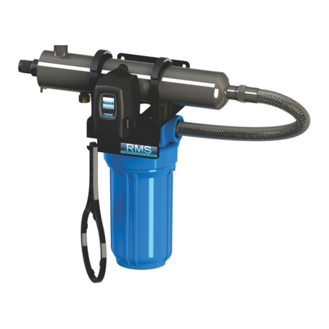
e DTS+SOLO is a standalone system, complete with dual inlet carbon and
particulate ltering, pump, panel, HMI touchscreen, R1 ROC control system,
and pressure vessel set (which house the reverse osmosis membranes).
e dual lters remove harmful chlorine and particulates from the dockwater
stream before they reach pump and membranes. e dual lter assembly has
a service valve, allowing the users to remove the inlet stream pressure aer
shutdown when replacing the carbon or particulate lter elements.
e membranes used in the DTS+SOLO are specially designed for purifying
freshwater, requiring lower pressure and energy than membranes designed for
purifying saltwater. e pump is matched to the lower pressure requirements
and is replaceable as a unit, eliminating the need to rebuild valves and seals.
e system is controlled by HMI touchscreen, an adjustable reject ow valve, and
an adjustable recycle ow valve. Pressure gauges and owmeters are provided
on the system panel. ese, along with information provided on the HMI
touchscreen, informs the operator of the state of the machine at a glance.
e DTS+SOLO advances the dockside treatment system lineage with
the introduction of a recycle valve technology. e recycle valve
technology increases the water recovery rate approximately 50%.
e DTS+SOLO is also versatile in its mounting requirements. e optional stand
allows the user to deck-mount the system’s panel and lters. Without the stand,
the user may wall-mount the system's panel and lters. If space is limited, the
user can mount the panel and lters separately (modular mount). e pressure
vessel set can be mounted horizontally or vertically, and includes mounting
rails. An installation kit is included to supply hose and tubing and ttings.
e practice of running dock water through a standard
seawater watermakers has been done for some time now.
1/ GENERAL

FCI WATERMAKERS, INC. 4General
PREFACE
We are committed to customer service that exceeds your expectations. If at any
time you have questions about what’s covered in this manual, our hands-on
technical support will never leave you adri. is manual contains technical
information & instructions for the installation, operation, maintenance, and
troubleshooting for FCI Watermakers Desalination Systems. Anyone responsible
for the installation, operation, and maintenance of a FCI Watermakers Desalination
System must read and understand the contents of this manual, and comply
with these instructions, guidelines, and safety requirements at all times.
e term system will be used throughout this manual, and it generally refers to
the FCI Watermakers DTS+SOLO. Reading this manual in its entirety will familiarize
you with the system and the operation of its components. By understanding
the system in its entirety, one can readily operate and diagnose problems.
All references within this manual refers to other sections unless specically
dened. Graphics and illustrations are used for reference only and may not
represent the actual part or arrangement of parts in a customized system.
ABOUT SAFETY NOTES
Safety issues requiring users attention are highlighted throughout this manual as follows:
WARNING: Provides critical information in order to
prevent the possibility of injuries and/or death.
CAUTION: Provides important information to prevent the
possibility of damaging the device or equipment.
NOTE: Provides additional information to safely
and properly operate the equipment.
NEW SYSTEM PERFORMANCE
Although each system has been fully tested prior to shipping, there will be a break-in
period. During this period, approximately 48 hours, membrane performance will
change or settle. Adjustments will need to be made to the reject ow valve, and the water
quality and quantity will vary. e reject ow valve will need to be increased (turned
clockwise) and the water quality produced will improve over this break-in period.

FCI WATERMAKERS, INC. 5General
e dockwater is delivered to the boat under city pressure. If the city pressure exceeds
50psi, the resulting pressure to the pump will be beyond the pump’s pressure limit. If
this is the case, a pressure regulator can be installed to keep the pressure before the pump
below the maximum limit. Contact the factory or your local FCI dealer for further details.
e dockwater passes through a service value and into the dual lters. First,
the particulate lter removes particles as small as 5 microns. Second, the
granular activated carbon lter removes chlorine and bromide, harmful
to the membranes of the watermaker. e service valve is used to remove
the city pressure when it is necessary to clean or replace the lters.
e ltered dockwater is then controlled by a solenoid valve. When the user starts the
DTS+SOLO via the HMI touchscreen, the solenoid valve opens, and aer priming, the
pump is turned on. Aer initializing, the pump will pressurize the dockwater stream to
operating pressure, and as the stream is passed over the membranes, product is pushed
through the membrane and impurities are washed away in the reject. Product water
quality is monitored by a TDS probe. A recycle valve reows approximately 50% of
the reject back into the dockwater stream, and the rest of the reject is sent to drain.
While running, the user adjusts the operating pressure with the reject owmeter
valve until the product output matches the rated output. Also, the user adjusts the
recycle owmeter valve until the recycle ow is approximately 50% of rated output.
e DTS+SOLO is designed especially for making
fresh drinking water from municipal water.
THEORY OF OPERATION

FCI WATERMAKERS, INC. 6General
FCI Watermakers warrants that all consumer systems perform according to the
specications for a period of one year from the date of installation or eighteen
(18) months from the date of shipment, whichever is earlier. FCI Watermakers
is not, under any circumstances, liable for any damages arising out of or in any
way connected with the failure of the system to perform as set forth herein. is
limited warranty is in lieu of all other expressed or implied warranties, including
those of merchantability and tness for a particular purpose. is warranty is
extended to the original owner / purchaser of record and is not transferable.
NOTE: Warranty registration is required to activate your warranty. Please be sure to ll
out the registration included in this manual and provide a copy to FCI Watermakers, Inc.
1.0 WARRANTY PERIOD
1.1 e following items are covered under warranty for the periods designated:
DTS+SOLO:
System and Accessories 1 (one) year from the date
of installation or 18 months
from the date of shipment,
whichever is earlier
Repairs aer warranty 3 (three) months
1.2 e following items are considered normal user maintenance
and are NOT covered under limited or implied warranty:
1 Sea Strainer Element 7 Pump Crankcase Oil
2 Cartridge Filter Elements 8 Gauge Instrument Calibration
3 Sand & Gravel in the MMF 9 Fuses
4 Pump Packing Assemblies 10 Valve Seals and Packings
5 Pump Seal Assemblies 11 Exterior Corrosion
6 Pump Valve Assemblies 12 Membrane Elements
1.3 Installation of components not supplied by FCI Watermakers,
is not covered by this or any limited warranty.
1.4 System failure or component failure or decline in performance as a result
of improper installation is not covered by this or any limited warranty.
is policy will dene, in detail, what is and is not
covered under warranty. It will also dene how
to obtain warranty service and approval.
LIMITED WARRANTY

FCI WATERMAKERS, INC. 7General
1.5 e Reverse Osmosis Membrane Elements are not covered under warranty
for any specic period by FCI Watermakers. Any misuse or improper
operation or maintenance of the system that causes premature fouling
of the Membrane Element is not under warranty. e warranty does not
cover a Membrane Element which has been subject to: iron fouling (rust),
chemical or petroleum products attack, extreme temperatures (over 120ºF
or under 32ºF), drying out or extreme pressures (over 1000 psi).
1.6 In the event of a defect, malfunction or failure, specically covered by
this warranty and during the warranty period, FCI Watermakers will
repair or replace, at its option, the product or component therein, which
upon examination by FCI Watermakers appears to be defective.
2.0 PROCEDURE FOR OBTAINING WARRANTY
2.1 e defective product or part must be returned to an authorized
FCI Watermakers Factory Service Center (dealer) or directly to FCI
Watermakers. e end user must pay any transportation and labor expenses
incurred in removing and returning the product to the service center
or FCI Watermakers, pending evaluation and warranty approval.
3.0 EXCEPTIONS AND LIMITATIONS
3.1 e limited warranty does not extend to any system or system component which
has been subjected to alteration, misuse, neglect, accident, improper installation,
inadequate or improper repair or maintenance or subject to use in violation of
instructions furnished by FCI Watermakers, nor does the warranty extend to
components on which the serial number has been removed, defaced or changed.
3.2 FCI Watermakers reserves the right to make changes or improvements in its
product, during subsequent production, without incurring the obligation to
install such changes or improvements on previously manufactured equipment.
3.3 e implied warranties, which the law imposes on the sale of this
product, are expressly LIMITED in duration to the time period
above. FCI Watermakers Corp. shall not be liable for damages,
consequential or otherwise, resulting from the use and operation of
this product, or from the breach of this LIMITED WARRANTY.
CAUTION: Use of non FCI Watermakers supplied parts and accessories, including but
not limited to maintenance parts, prelter elements, membranes, cleaning and storage
chemical, pump oil, spare parts, replacement parts, system components, installation
components and/or system accessories, shall void all warranty expressed or implied.
LIMITED WARRANTY (continued)

FCI WATERMAKERS, INC. 8General
WARRANTY REGISTRATION
INSTRUCTIONS: At the time of purchase of the FCI Watermakers
system, please complete the warranty information listed
below. Aer completing this form, please make a copy and
submit the copy using one of the options at the bottom of the
page. Keep this copy in your manual for future reference.
Mail a copy to:
FCI WATERMAKERS, INC
ATTENTION: WARRANTY REGISTRATION
3782 W 2340 S, STE E
WEST VALLEY CITY, UT 84120-7291 USA
EMAIL: info@fciwatermakers.com
Subject: Warranty Registration
FAX: +1-801-883-9985
SYSTEM INFORMATION:
Model #
Serial #
Operating Voltage:
Date Purchased:
Date Commissioned:
DEALER INFORMATION:
Dealer Name:
Address:
City: State:
Country: Postal Code:
Dealer Invoice #:
CUSTOMER INFORMATION:
Customer Name:
Address:
City:
State: Postal Code:
Country:
Phone: Fax:
E-mail:
VESSEL INFORMATION:
Boat Manufacture:
Boat Model:
Boat Name:
Boat Length:
LAND BASED INFORMATION:
Installation site:
Site Name: (resort, company etc)
Application:
Operator Contact Information:
(person in charge of system maintenance and operation)
Name:
E-mail:
Phone:

FCI WATERMAKERS, INC. 9General
Copyright 2020 FCI Watermakers, Incorporated. All content included within
this manual, such as text, graphics, logos, and images, is the property of FCI
Watermakers, Inc. and protected by U.S. and international copyright laws.
e compilation (meaning the preparation, collection, arrangement, and
assembly) of all content within this manual is the exclusive property of FCI
Watermakers, Inc. and protected by U.S. and international copyright laws.
All soware used in the design and manufacture of a FCI Watermakers Reverse Osmosis
Desalination System is the property of FCI Watermakers, Inc. and protected by U.S. and
international copyright laws. All computer and logic programming used in the design and
manufacture of a FCI Watermakers Reverse Osmosis Desalination System is the property
of FCI Watermakers, Inc. and protected by U.S. and international copyright laws.
e content of this manual and the soware, programming, and graphic designs
used in the design and manufacture of a FCI Watermakers Reverse Osmosis
Desalination System is for the purpose of operation, maintaining, and repair of a
FCI Watermakers Reverse Osmosis Desalination System. Any other use, including
the reproduction, modication, distribution, transmission, republication, display,
or performance, of the content within this manual is strictly prohibited.
TERMS AND CONDITIONS— e use of this manual acknowledges acceptance
of the terms and conditions provided herewith and the agreement to comply
with all applicable laws and regulations pertaining to the use of this manual.
In addition, the use of this manual forms an agreement that FCI Watermakers,
Inc.’s trademarked name or FCI Watermakers, Inc. trademarked logo mark
are not to be used in any form or manner except with FCI Watermakers’
written permission. FCI Watermakers, Inc. holds all rights to its copyrights
and trademarks, and to the material contained in this manual. Any use of
such requires the written permission from FCI Watermakers, Inc.
PATENT INFORMATION— Certain aspects of a FCI Watermakers Reverse Osmosis
Desalination System are protected by U.S. and International Patent Laws.
NOTICE OF LIABILITY— e information contained in the manual is distributed
on an “As is” basis, without warranty. While every eort has been taken in the
preparation of this manual, FCI Watermakers, Inc. shall not be held liable with respect
to any liability, loss, or damage caused by the instructions contained in this manual.
e information contained in this manual is subject to change without notice.
TRADEMARKS— FCI Watermakers logo mark is a U.S. Registered
Trademark and belongs to FCI Watermakers, Inc. with all rights reserved.
FCI Watermakers is a US Registered trademark of FCI Watermakers, Inc. FCI
Aquamiser+, Max•Q, Max•Q+, Max•Q+APC, Neptune, Neptune+, Neptune+APC,
Neptune Horizontal Econ, Poseidon, Poseidon+, Poseidon+APC, Titan, DTS,
DTS+, DTS+AUTO, DTS+RETRO, DTS+SOLO, UROC (Universal Reverse Osmosis
Controller), V4 Control are trademarks of FCI Watermakers, Inc.
COPYRIGHT NOTIFICATION

FCI WATERMAKERS, INC. 10General
FCI WATERMAKERS, INC.
3782 W 2340 S, STE E
WEST VALLEY CITY, UT 84120-7291
phone: 801 906 8840
fax: 801 883 9985
email: info@fciwatermakers.com
fciwatermakers.com
FCI CONTACT INFORMATION
If you have questions regarding your FCI Watermakers system
or the contents of this manual, or if you need replacement
parts, please do not hesitate to contact us immediately. Our
hands-on technical support is always at your service.

FCI WATERMAKERS, INC. 11General
TABLE OF CONTENTS
1/ GENERAL
PREFACE 4
THEORY OF OPERATION 5
LIMITED WARRANTY 6
WARRANTY REGISTRATION 8
COPYRIGHT NOTIFICATION 9
FCI CONTACT INFORMATION 10
TABLE OF CONTENTS 11
TABLE OF FIGURES 12
TABLE OF TABLES 12
GENERAL INFORMATION 13
2/ PRE-INSTALLATION
COMPONENT IDENTIFICATION 17

INSTALLATION KITS 18
PIPING & INSTRUMENTATION DIAGRAM 19
COMPONENT DESCRIPTIONS 20
3/ INSTALLATION
COMPONENTS SUPPLIED BY INSTALLER 26
DIMENSIONS, WEIGHT & FOOTPRINTS 27
GENERAL CONNECTION DIAGRAMS 31
SYSTEM INSTALLATION / MOUNTING 32
SYSTEM INSTALLATION / PLUMBING 33
SYSTEM INSTALLATION / ELECTRICAL CONNECTIONS 36
SCHEMATICS 39
INSTALLATION CHECKLIST 40
4/ OPERATIONAL INSTRUCTIONS
TEMPERATURE & PRESSURE EFFECTS CHART 42
OPERATING THE DTS+SOLO 43
R1 ROC OVERVIEW 44
DISPLAYS AND GRAPHICS 45
DISPLAY SCREENS 47
SYSTEM FUNCTIONALITY 52
SYSTEM ALARMS 54
5/ MAINTENANCE & REPAIR
MEMBRANE REPLACEMENT 55
STORAGE AND WINTERIZING PROCEDURES 58
6/ PARTS
ILLUSTRATED PARTS / DTS+SOLO 60
ILLUSTRATED PARTS / PUMP & MOTOR 64
ILLUSTRATED PARTS / PRESSURE GAUGES 65
ILLUSTRATED PARTS / FLOW METERS 67
ILLUSTRATED PARTS / ELECTRICAL 70
ILLUSTRATED PARTS / FILTER ASSEMBLY 72
ILLUSTRATED PARTS / PRESSURE VESSELS 73
7/ REVISION HISTORY
REVISION HISTORY 77

FCI WATERMAKERS, INC. 12General
TABLE OF FIGURES
TABLE OF TABLES
Figure 1: Component Identication 17
Figure 2: Installation Kit (P/N 93-5419) 18
Figure 3: Piping & Instrumentation Diagram 19
Figure 4: Deck Mount. Wall Mount, or Modular Mount 20
Figure 5: Filter Assembly Features 22
Figure 6: Panel Assembly Features 23
Figure 7: Pressure Vessel Set Features 24
Figure 8: Dimensions - Stand for Deck Mount 27
Figure 9: Dimensions - Wall Mount 28
Figure 10: Dimensions - Modular Mount 29
Figure 11: Dimensions - Pressure Vessel Sets 30
Figure 12: General Connection Diagram 31
Figure 13: Proper Installation of Hose Ends and Fittings 33
Figure 14: Plumbing Connections 35
Figure 15: Wiring the Power Supply 37
Figure 16: Wiring the Solenoid (modular mount only) 38
Figure 17: Schematics 39
Figure 18: Water Temperature vs. Output (constant pressure) 42
Figure 19: Operating the DTS+SOLO 43
Figure 20: Replacing the Membrane 56
Figure 21: 1 PV for 2,000 GPD Rated Systems (P/N 93-5414) 56
Figure 22: 2 PVs for 3,000 GPD Rated Systems (P/N 93-5415) 57
Table 1: Specications for Components Supplied by Installer 26
Table 2: Hose, Tubing, Route & Description 34

FCI WATERMAKERS, INC. 13General
GENERAL INFORMATION
FCI watermakers are the most advanced desalinating systems
available, which produce potable water from seawater or brackish
water. For over a decade, FCI Watermakers, Inc. has pioneered
technology and innovated features that have become standards for
today’s desalinators: one-touch commands, multiple station operation,
and remote system control and monitoring. As both engineers
and crasmen, we specialize in high-performance, value-driven
watermakers and are proud of the thousands of continuously
operating units that have been cruising the globe for decades.
At FCI Watermakers, our commitment and attention to detail transcends beyond
materials and construction. ings that are seemingly trivial are never overlooked. For
instance, your system’s specications formulate the Model Number. It is comprised of the
Series, the Model Name, and the Production Rating of the unit in gallons per day (GPD):
DTS+SOLO-3000
Series
DTS+: DTS+Series
DTS Production
-2000: 2,000 GPD
-3000: 3,000 GPD
Model Name
SOLO: DTS+SOLO
A
A
B C
B C
Your FCI Reverse Osmosis Desalination System is designed to provide lasting
performance using high-grade materials and uncompromising engineering. FCI
systems utilize high-grade alloys in critical components, where competing brands oen
use inferior material that compromise system operation and jeopardize the vessel.
NEW SYSTEM PERFORMANCE
Although each system has been fully tested prior to shipping, there will be a break-in
period. During this period, approximately 48 hours, membrane performance will
change or settle. Adjustments will need to be made to the reject ow valve, and the water
quality and quantity will vary. e reject ow valve will need to be increased (turned
clockwise) and the water quality produced will improve over this break-in period.

FCI WATERMAKERS, INC. 14Pre-Installation
e FCI Watermakers System is supplied with an installation kit which includes
an assortment of hoses needed to install the system. Because of the various
options with regard to location, some installations may require additional
hose or wire. Please contact your local dealer for these supplies. Be sure to
follow all local codes when installing your new FCI watermaking system.
Always use genuine FCI approved parts to ensure proper operation of your watermaker.
PREINSTALLATION PRECAUTIONS
STORAGE PRIOR TO REMOVAL FROM CRATE
Adhere to crate markings:
• DO NOT store in direct sunlight;
• DO NOT store above 120º F (50º C);
• DO NOT freeze;
• DO NOT store longer than 4 months without ushing with storage chemical;
• STORE ONLY on base with ARROWS UP;
• KEEP THE R.O. MEMBRANE ELEMENT WET AT ALL TIMES.
REVERSE OSMOSIS MEMBRANE ELEMENT IS
SUSCEPTIBILITY TO CHEMICAL ATTACK
CAUTION: Do Not expose the FCI Watermakers system to
intake Feed Water from any chemical not approved in writing
by FCI Watermakers, or any of the following chemicals:
• Hydrogen peroxide • Chloramines-T
• Chlorine dioxide • Chlorine
• Bromine phenolic • Disinfectants
• Chloramines • N-chlorioisocyanurates
• Hypochlorite • Iodine
• Bromide • Petroleum products
USE OF NONAUTHORIZED OR MISUSE OF AUTHORIZED
CHEMICALS VOIDS SYSTEM WARRANTY
Do not connect any water line to the system that may contain any of the
aforementioned chemicals. Example: Do not connect the inlet of the system
to the ship’s potable water system or the dockside water system without the
lter assembly, if the water systems contain chlorinated or brominated water.
ese chemicals destroy the copolymer components within the R.O. system.
ese oxidants and others also damage the R.O. membrane element.
is section provides key information for a successful install, leading
to long-term enjoyment of your FCI watermakers. It includes
warnings, cautions and notes associated with the preparatory work
necessary to properly install and maintain your watermaking system.
2/ PRE-INSTALLATION

FCI WATERMAKERS, INC. 15Pre-Installation
DO NOT PERFORM INSTALLATION UNLESS:
1 . e system feed water valve is closed.
2. e system main electrical disconnect switch is switched
“OFF,” LOCKED, and TAGGED.
WARNING: ELECTRICAL SHOCK HAZARD.e installation
procedures expose the installer to HIGH VOLTAGE and electrical
shock hazard. Only attempt installation if you are a qualied
electrician and only if surrounding conditions are safe.
QUALIFICATIONS
Technicians must have technical knowledge and ability
in the following elds:
a) Electrical, Electronic, Electric Motors and Circuits
b) Electromechanical and Mechanical Systems
c) Hydraulic and Liquid Pressure and Flow Systems
d) Piping and Plumbing Systems
e) Water Suction and Pressure Lines
f) ru-Hull Fitting below and above water level
WARNING: Do not attempt installation, commissioning, troubleshooting,
or repair if you are not procient in the above elds of expertise.
SPECIAL CONSIDERATIONS INSTALLATION CAUTIONS
Always allow hoses and tubes to enter and exit straight from the connection
for a minimum of one inch prior to a bend. If stress is placed on the
tting due to a tight bend, the tting will leak and may break.
Avoid skin and eye contact with the membrane packaging solution. In
case of skin contact, rinse the skin thoroughly with water. In case of eye
contact, ush repeatedly with water and notify a physician immediately.
R.O. membrane elements are stored in “sodium bisulte.”
NEVER mount liquid-holding component above any electrical or
electronic device. Extensive damage to the electronic device will result
if liquid enters device during maintenance or component failure.
CONNECTION LINE CAUTIONS: All connection lines
should be as short and straight as possible using minimum
ttings. e connection lines must not be “kinked.”
ACCESSIBILITY CAUTIONS: is is a simple rule. Install
the system and its supporting components in an accessible manner.
e panel must be accessible for operation of the system.
PRE-INSTALLATION (continued)

FCI WATERMAKERS, INC. 16Pre-Installation
R.O. MEMBRANE ELEMENT NOTES
CAUTION: Some systems are shipped WITHOUT the reverse osmosis
membrane element. is is to accommodate boat builders that will install
the system well in advance of commissioning the boat and the system.
DOES THIS SYSTEM HAVE R.O. MEMBRANES
INSTALLED OR NOT?
If not, is it your intention to install the R.O. membrane(s) at this time, or do
you wish to install them at a later date when the boat is commissioned?
If the R.O. membrane element has been installed, there will be a R.O. membrane
element serial number tag attached to the pressure vessel(s). Find this serial
number tag to ensure that the R.O. membrane element(s) have been installed.
If the R.O. membrane element serial number tag is missing or does not
contain a serial number, then the R.O. membranes are not installed. If the
R.O. membrane elements are not installed and you wish to install them at this
time, contact FCI Watermakers, Inc. and supply us with your original purchase
order number, FCI’s invoice number, and this system’s serial number.
WARNING: If the reverse osmosis membrane element is not to be installed
at this time, ensure that you leave a visible note at the system controller
and at the front of the control panel informing the end user that:
e reverse osmosis membrane elements are not installed;
to contact the factory for the R.O. membrane elements; and
DO NOT operate the system without the R.O. membrane
elements installed. Extensive damage will occur if the system is
operated without the R.O. membrane elements installed.
Damage to the system caused by the operation of the system without
R.O. membrane elements installed:
• Is NOT covered by the FCI Watermakers, Inc. warranty
• Is the liability of the installer if the installer did not notify the end user.
• Is the liability of the end user if the installer notied the end user
that the R.O. membranes were not installed and to not operate
the system without the R.O. membrane elements installed.
PRE-INSTALLATION (continued)

FCI WATERMAKERS, INC. 17Pre-Installation
Figure 1 introduces the components required for the
install. Each component plays an important part in the
install and is referenced throughout this manual.
COMPONENT IDENTIFICATION
Figure 1: Component Identication
3. Installation Kit (93-5419)
1. DTS+SOLO Assembly (P/N 93-5338)
Optional Stand
(P/N 90-5382)
Inlet Filter Assembly
(P/N 93-5365)
Contains replaceable
GAC Filter 4.5 x 10"
(P/N 20-0026)
Contains replaceable
5 micron filter
(P/N 20-0021)
The DTS+SOLO may be mounted in three configurations:
2. Pressure Vessel Set
2,000 GPD Rated System
(P/N 93-5414)
3,000 GPD Rated System
(P/N 93-5415) Pre-Installed Pressure Vessel Fittings
Flow In
Product Out
Reject Out
1
2
3
3
3
1
1
2
2
- or -
- or - - or -
Panel Assembly
(P/N 90-5337)
Deck Mount
(with optional stand)
Wall Mount
Modular Mount

FCI WATERMAKERS, INC. 18Pre-Installation
INSTALLATION KITS
e installation kit provided with DTS+SOLO
will match the kit shown in Figure 2.
Figure 2: Installation Kit (P/N 93-5419)
Tubing, 3/8" OD x .048 Wall
250 PSI (P/N 74-4261-40ft)
Tubing, 3/8" PE
(P/N 74-0473-40ft)
Tubing, 1/2" PE
(P/N 74-0474-20ft)
Connector, Straight, PE, Black
1/2" MPT x 1/2" Tube
(P/N 74-0446)
Connector, Straight, PE, Black
3/8" MPT x 3/8" Tube
(P/N 74-0446)
Hose Clamp #12
3/4"-1-1/4", SS
(Qty 4, P/N 73-0485)
Manual, DTS+SOLO
(P/N 97-5420)
Wrench, Filter, JB Housing
(P/N 22-0036)
Hose, 3/4", Suction
PVC Helix Wire
(P/N 74-2279-20ft)

FCI WATERMAKERS, INC. 19Pre-Installation
PIPING & INSTRUMENTATION DIAGRAM
Figure 3: Piping & Instrumentation Diagram
Figure 3 shows the piping and interconnect of the components,
including standard and optional accessory congurations. Determine
the pre-ltration and post-ltration components that were supplied
with your system, and identify how each component interconnects.
Pre-FilterGAC
PI
PI PS
PS
FM
HP Pump
Adjustable
Reject
Flow
Meter
Adjustable
Recycle
Flow Meter
Fresh Water Vessel Setup (1 or 2)
TDS Probe
Product
Flow Meter
Ultraviolet
To Ship’s Fresh
Water System
Ultraviolet Check Valve
Product
Water
Tank
Ship’s Supply
Remineralization
Filter
GAC Filter Bladder Tank
Fresh Water
Pump
Dock
Water
Inlet
Reject
Discharge
FM
FM
Check Valve
Ball Valve
2 Way Solenoid Valve
Flow Meter
Legend
FM
Pressure Gauge
PI
Pressure Switch
PS

FCI WATERMAKERS, INC. 20Pre-Installation
Use of third party, Non-FCI (or unauthorized) components may lead to premature
failure, added operating and maintenance costs, and increased labor. Using 3rd party,
Non-FCI components may void any and all FCI Watermakers Warranty. We only wish
to help you enjoy the luxury of owning a FCI Desalinating System. Treat it properly by
using only FCI supplied parts, recommended consumables, and authorized accessories.
DECK MOUNT, WALL MOUNT OR MODULAR MOUNT
e DTS+SOLO may be installed using the optional stand (deck mount), or without the
stand (wall mount), or with panel and lter separated (modular mount). e deck
mount consists of securing the stand with screws to the deck. e wall mount consists
of securing the panel and lter assembly with screws to the wall. e modular mount
consists of separating the lter and panel and mounting separately. e pressure
vessel set will be secured separately in all mounting congurations. See Figure 4.
COMPONENT DESCRIPTIONS
Standard and optional components are described in this section, and
items required by the installer are listed. e location, operation, and
purpose of each major component of the system is briey explained.
- or - - or -
Deck Mount Wall Mount Modular Mount
Optional
Stand
Figure 4: Deck Mount. Wall Mount, or Modular Mount
INSTALLATION KIT
e installation kit supplies hose, tubing, clamps and ttings to connect the
plumbing. Some ttings may be shipped attached to components. For custom
installation, you made need to order additional lengths of hoses and tubes. Wire
is not supplied because the required lengths varies per installation. Wire is needed
for power connection. If you intend to install using a modular mount, extra wire
may be needed to connect the solenoid of the lter assembly to the panel.
This manual suits for next models
4
Table of contents
Other FCI Watermakers Water Filtration System manuals
Popular Water Filtration System manuals by other brands

Nimbus Water Systems
Nimbus Water Systems Five Water Maker WM5-50 Instruction

Pondlink
Pondlink System Feeder user manual

APSWATER
APSWATER RO10D1 OPERATING AND INSTALLATION Manual

Asutec
Asutec ASREL-003 Assembly instruction

Oase
Oase ProfiClear Premium XL operating instructions

smartmi
smartmi ZMFL-1-FLA user manual