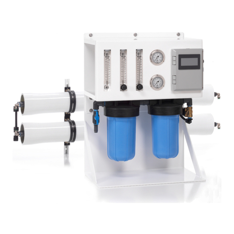
FCI Watermakers MAX-Q+ Installation and operating instructions


FCI WATERMAKERS, INC. 3FCI WATERMAKERS, INC. General
ank you for purchasing FCI Watermakers Reverse Osmosis System. Your choice
of FCI Watermakers proves that quality, crasmanship and performance do matter.
e system you have chosen is of the highest quality, and it is the most advanced
watermaker available today. Over 25 years of experience of engineering and extensive
lab testing has gone into the design of your watermaker. In fact many industry
standards are a result of innovations made by FCI Watermakers, including one‑touch
commands, multiple station operation, remote system control, touchscreen displays,
and automated pressure control. Each component was chosen for its ability to
withstand the marine environment and to provide a lifetime of trouble‑free operation.
Design considerations included noise, size, ease of use and simple maintenance. Its
open‑frame construction allows quick, easy inspections, and it aids in shipboard
or land‑based maintenance without having to move the system from its location.
e intent of this manual is to allow the operator to become familiar with
each component of the reverse osmosis system. By understanding the
function, importance, and normal operation of each watermaker module,
the operator can readily diagnose minor problems. When such problems
rst arise, they usually require minor maintenance and the issue is easily
corrected. However, if le unattended, a problem in one component may
eventually aect the rest of the system and it could lead to further repairs.
FCI Watermakers systems use non‑proprietary membranes that are readily
available worldwide, and the systems are designed to be more tolerant of
water conditions. Your vessel travels around the world and encounters
water that varies in both salinity and particulate. FCI utilizes low RPM
components that allow full function operation in these conditions.
FCI has the most comprehensive warranty on the market. e Max•Q+system
is covered for one year on all non‑consumable parts. A copy of our warranty
is included in this manual. Please read and familiarize yourself with it.
Congratulations on joining an elite group of like-minded boat
and yacht owners, who value their investment and have chosen
the industry’s most reliable and advanced marine reverse
osmosis system available. A great deal of time and eort has
been put into the design and manufacture of your new FCI
Watermakers desalination system. Please take time to read
this entire manual and familiarize yourself with its operation.
It will benet you by insuring long trouble-free operation.
1/ GENERAL

FCI WATERMAKERS, INC. 4FCI WATERMAKERS, INC. General
PREFACE
We are committed to customer service that exceeds your expectations. If at any
time you have questions about what’s covered in this manual, our hands‑on
technical support will never leave you adri. is manual contains technical
information & instructions for the installation, operation, maintenance, and
troubleshooting for FCI Watermakers Desalination Systems. Anyone responsible
for the installation, operation, and maintenance of a FCI Watermakers Desalination
System must read and understand the contents of this manual, and comply
with these instructions, guidelines and safety requirements at all times.
e term system will be used throughout this manual, and it generally refers to
the FCI Watermakers System. Reading this manual in its entirety will familiarize
you with the system and the operation of its components. By understanding
the system in its entirety, one can readily operate and diagnose problems.
All references within this manual refer to other sections unless specically
dened. Graphics and illustrations are used for reference only and may not
represent the actual part or arrangement of parts in a customized system.
ABOUT SAFETY NOTES
Safety issues requiring users attention are highlighted throughout this manual as follows:
WARNING:
Provides critical information in order to prevent the possibility of injuries and/or death.
CAUTION:
Provides important information to prevent the possibility
of damaging the device or equipment.
NOTE:
Provides additional information to safely and properly operate the equipment.
NEW SYSTEM PERFORMANCE
Although each system has been fully tested prior to shipping, there will be a
break‑in period. During this period, approximately 48 hours, the pumps and
membrane performance will change or settle. Small adjustments will need to be
made to the high‑pressure valve and the water quality and quantity will vary.
For installations without APC, the high‑pressure valve will need to be increased
(turned clockwise) and the water quality produced will improve over this break‑
in period. For systems with APC, this adjustment will be automatic.

FCI WATERMAKERS, INC. 5FCI WATERMAKERS, INC. General
BOUNDARY LAYER / CONCENTRATION POLARIZATION
When water permeates through the membrane, nearly all the salt is le
behind in the brine channel. In any dynamic hydraulic system, the uid
adjacent to the wall of the vessel is moving relatively slow. Even though
the main body of the stream is turbulent, a thin lm adjacent to the wall
(membrane) is laminar. is thin lm is called the boundary layer.
If the feed water ow is insucient, the salts are saturated at the boundary layer
and can readily adhere to and pack into the R.O. membrane element surface.
For this reason, it is important to maintain sucient feed water ow through
the R.O. membrane element and prevent concentration polarization.
BRINE VELOCITY
e brine velocity, or ow, over the membrane surface is very important
to both product water quality and quantity. At low ows, concentration
polarization occurs, causing the water quality to decline.
In addition to inferior product water quality, low brine ows can
increase the precipitation of sparingly soluble salts. e salts will foul
the R.O. membrane element surface (concentration polarization). If
this occurs, the product water ux (production) will decline.
e feed pump integrated design provides a relatively smooth and continual
ow of feed water across and through the R.O. membrane element.
COMPACTION
Some densication of the membrane structure may take place while operating
at elevated pressures, above 1000 PSI. e change is known as compaction
and is accompanied by a reduction in the water permeation rate.
When the R.O. membrane element is subjected to elevated pressures
beyond 1000 PSI, the product water channel becomes squeezed,
resulting in restriction and product water recovery reduction.
OSMOTIC PRESSURE
e transfer of the water from one side of the membrane to the other will
continue until the head (pressure) is great enough to prevent any net transfer
of the solvent (water) to the more concentrated (feed water) solution.
At equilibrium, the quantity of water passing in either direction is equal,
and the head pressure is then dened as the "osmotic pressure" of the
solution having that particular concentration of dissolved solids.
Following terms are helpful in becoming familiar with
a FCI Watermakers Reverse Osmosis System.
GLOSSARY OF TERMS

FCI WATERMAKERS, INC. 6FCI WATERMAKERS, INC. General
PRESSURE
e operating pressure has a direct eect on product water quality and quantity.
Both factors will increase as the system pressure increases (within design limits).
e system must be operated at the lowest pressure required to achieve
the designed product water ow rate. is parameter also minimizes
compaction, which occurs faster at higher pressures and temperatures.
At low temperatures or high salinity feed water, the system will have to operate at
higher than normal pressure to maintain the specied amount of product water
ow. is is normal and is due to the design characteristics of the system.
SPIRALWOUND MEMBRANE
e spiral‑wound membrane consists of multiple membrane envelopes, each
formed by enclosing a channelized product water carrying material between two
large at membrane sheets. e membrane envelope is sealed on three edges with
a special adhesive and attached with the adhesive to a small diameter pipe.
A polypropylene screen is used to form the feed water channel between the membrane
envelopes. A wrap is applied to the membrane element to maintain the cylindrical
conguration. e center tube is also the permeate (product water) collecting channel.
Several elements may be connected in series within single pressure vessel
or multiple pressure vessels.
WATER TEMPERATURE EFFECT
e product water ow through the membrane is signicantly aected
by the water temperature. At any given pressure, this ow increases with
increasing water temperature and is reduced at lower temperatures. e system
pressure will need to be adjusted to maintain a precise amount of product
water ow. For systems with APC, this adjustment will be automatic.
GLOSSARY OF TERMS (continued)

FCI WATERMAKERS, INC. 7FCI WATERMAKERS, INC. General
FCI Watermakers warrants that consumer systems perform according to the
specications for a period of one year from the date of the date of shipment. FCI
Watermakers is not, under any circumstances, liable for any damages arising out
of or in any way connected with the failure of the system to perform as set forth
herein. is limited warranty is in lieu of all other expressed or implied warranties,
including those of merchantability and tness for a particular purpose. is warranty
is extended to the original owner / purchaser of record and is not transferable.
NOTE: Warranty registration is required to activate your warranty. Please be sure to ll
out the registration included in this manual and provide a copy to FCI Watermakers, Inc.
1.0 WARRANTY PERIOD
1.1 e following items are covered under warranty for the periods designated:
Max•Q+and Max•Q+APC Systems:
System and Accessories 1 (one) year from the date
of shipment of the System
Pressure Vessel Tubes Lifetime
Repairs aer warranty 3 (three) months
1.2 e following items are considered normal user maintenance
and are NOT covered under limited or implied warranty:
1 Sea Strainer Element 7 Gauge Instrument Calibration
2 Cartridge Filter Elements 8 Fuses
3 Pump Packing Assemblies 9 Valve Seals and Packings
4 Pump Seal Assemblies 10 Exterior Corrosion
5 Pump Valve Assemblies 11 Membrane Elements
6 Pump Crankcase Oil
1.3 Installation of components not supplied by FCI Watermakers,
is not covered by this or any limited warranty.
is policy will dene, in detail, what is and is not
covered under warranty. It will also dene how
to obtain warranty service and approval.
LIMITED WARRANTY

FCI WATERMAKERS, INC. 8FCI WATERMAKERS, INC. General
1.4 System failure or component failure or decline in performance as a result
of improper installation is not covered by this or any limited warranty.
1.5 e Reverse Osmosis Membrane Elements are not covered under warranty
for any specic period by FCI Watermakers. Any misuse or improper
operation or maintenance of the system that causes premature fouling
of the Membrane Element is not under warranty. e warranty does not
cover a Membrane Element which has been subject to: iron fouling (rust),
chemical or petroleum products attack, extreme temperatures (over 120ºF
or under 32ºF), drying out or extreme pressures (over 1000 psi).
1.6 In the event of a defect, malfunction or failure, specically covered by
this warranty and during the warranty period, FCI Watermakers will
repair or replace, at its option, the product or component therein, which
upon examination by FCI Watermakers appears to be defective.
2.0 PROCEDURE FOR OBTAINING WARRANTY
2.1 e defective product or part must be returned to an authorized
FCI Watermakers Factory Service Center (dealer) or directly to FCI
Watermakers. e end user must pay any transportation and labor expenses
incurred in removing and returning the product to the service center
or FCI Watermakers, pending evaluation and warranty approval.
3.0 EXCEPTIONS AND LIMITATIONS
3.1 e limited warranty does not extend to any system or system component which
has been subjected to alteration, misuse, neglect, accident, improper installation,
inadequate or improper repair or maintenance or subject to use in violation of
instructions furnished by FCI Watermakers, nor does the warranty extend to
components on which the serial number has been removed, defaced or changed.
3.2 FCI Watermakers reserves the right to make changes or improvements
in its product, during subsequent production, without incurring the obligation
to install such changes or improvements on previously manufactured equipment.
3.3 e implied warranties, which the law imposes on the sale of this
product, are expressly LIMITED in duration to the time period
above. FCI Watermakers Corp. shall not be liable for damages,
consequential or otherwise, resulting from the use and operation of
this product, or from the breach of this LIMITED WARRANTY.
CAUTION: Use of non FCI Watermakers supplied parts and accessories, including but
not limited to maintenance parts, pre-lter elements, membranes, cleaning and storage
chemical, pump oil, spare parts, replacement parts, system components, installation
components and/or system accessories, shall void all warranty expressed or implied.
LIMITED WARRANTY (continued)

FCI WATERMAKERS, INC. 9FCI WATERMAKERS, INC. General
WARRANTY REGISTRATION
INSTRUCTIONS: At the time of purchase of the FCI Watermakers
system, please complete the warranty information listed
below. Aer completing this form, please make a copy and
submit the copy using one of the options at the bottom of the
page— Keep this copy in your manual for future reference.
Mail a copy to:
FCI WATERMAKERS, INC
ATTENTION: WARRANTY REGISTRATION
3782 W 2340 S, STE E
WEST VALLEY CITY, UT 84120‑7291 USA
E‑MAIL: info@fciwatermakers.com
Subject: Warranty Registration
FAX: +1‑801‑883‑9985
SYSTEM INFORMATION:
Model #
Serial #
Operating Voltage:
Date Purchased:
Date Commissioned:
DEALER INFORMATION:
Dealer Name:
Address:
City: State:
Country: Postal Code:
Dealer Invoice #:
CUSTOMER INFORMATION:
Customer Name:
Address:
City:
State: Postal Code:
Country:
Phone: Fax:
E‑mail:
VESSEL INFORMATION:
Boat Manufacture:
Boat Model:
Boat Name:
Boat Length:
LAND BASED INFORMATION:
Installation site:
Site Name: (resort, company etc)
Application:
Operator Contact Information:
(person in charge of system maintenance and operation)
Name:
E‑mail:
Phone:
COMMERCIAL APPLICATION:
Rig Name:
Rig Location:
Operator Name:
Operator E‑mail:

FCI WATERMAKERS, INC. 10FCI WATERMAKERS, INC. General
Copyright 2014 FCI Watermakers, Incorporated. All content included within
this manual, such as text, graphics, logos, and images, is the property of FCI
Watermakers, Inc. and protected by U.S. and international copyright laws.
e compilation (meaning the preparation, collection, arrangement, and
assembly) of all content within this manual is the exclusive property of FCI
Watermakers, Inc. and protected by U.S. and international copyright laws.
All soware used in the design and manufacture of a FCI Watermakers Reverse Osmosis
Desalination System is the property of FCI Watermakers, Inc. and protected by U.S. and
international copyright laws. All computer and logic programming used in the design and
manufacture of a FCI Watermakers Reverse Osmosis Desalination System is the property
of FCI Watermakers, Inc. and protected by U.S. and international copyright laws.
e content of this manual and the soware, programming, and graphic designs
used in the design and manufacture of a FCI Watermakers Reverse Osmosis
Desalination System is for the purpose of operation, maintaining, and repair of a
FCI Watermakers Reverse Osmosis Desalination System. Any other use, including
the reproduction, modication, distribution, transmission, republication, display,
or performance, of the content within this manual is strictly prohibited.
TERMS AND CONDITIONS— e use of this manual acknowledges acceptance
of the terms and conditions provided herewith and the agreement to comply
with all applicable laws and regulations pertaining to the use of this manual.
In addition, the use of this manual forms an agreement that FCI Watermakers,
Inc.’s trademarked name or FCI Watermakers, Inc. trademarked logo mark
are not to be used in any form or manner except with FCI Watermakers’
written permission. FCI Watermakers, Inc. holds all rights to its copyrights
and trademarks, and to the material contained in this manual. Any use of
such requires the written permission from FCI Watermakers, Inc.
PATENT INFORMATION— Certain aspects of a FCI Watermakers Reverse Osmosis
Desalination System are protected by U.S. and International Patent Laws.
NOTICE OF LIABILITY— e information contained in the manual is distributed
on an “As is” basis, without warranty. While every eort has been taken in the
preparation of this manual, FCI Watermakers, Inc. shall not be held liable with respect
to any liability, loss, or damage caused by the instructions contained in this manual.
e information contained in this manual is subject to change without notice.
TRADEMARKS— FCI Watermakers logo mark is a U.S. Registered Trademark and
belongs to FCI Watermakers, Inc. with all rights reserved. FCI Watermakers is a
US Registered trademark of FCI Watermakers, Inc. FCI Aqualite, Aquamiser Plus
(+), Max•Q, Max•Q+, MaxQ+APC, Neptune, Poseidon, Titan and UROC (Universal
Reverse Osmosis Controller) are trademarks of FCI Watermakers, Inc.
COPYRIGHT NOTIFICATION

FCI WATERMAKERS, INC. 11FCI WATERMAKERS, INC. General
FCI WATERMAKERS, INC.
3782 W 2340 S, STE E
WEST VALLEY CITY, UT 84120‑7291
phone: 801 906 8840
fax: 801 883 9985
e‑mail: info@fciwatermakers.com
fciwatermakers.com
FCI CONTACT INFORMATION
If you have questions regarding your FCI Watermakers system
or the contents of this manual, or if you need replacement
parts, please do not hesitate to contact us immediately. Our
hands-on technical support is always at your service.

FCI WATERMAKERS, INC. 12FCI WATERMAKERS, INC. General
TABLE OF CONTENTS
1/ GENERAL
PREFACE 4
GLOSSARY OF TERMS 5
LIMITED WARRANTY 7
WARRANTY REGISTRATION 9
COPYRIGHT NOTIFICATION 10
FCI CONTACT INFORMATION 11
TABLE OF CONTENTS 12
TABLE OF FIGURES AND TABLES 14
GENERAL INFORMATION 15
THEORY OF OPERATION 16
2/ PRE-INSTALLATION
SYSTEM COMPONENTS IDENTIFICATION 22
PIPING & INTERCONNECT DIAGRAM 23
COMPONENT DESCRIPTIONS 24
3/ INSTALLATION
COMPONENTS SUPPLIED BY INSTALLER 29
INSTALLATION KITS 31
DIMENSIONS & FOOTPRINT 32
PLUMBING DIAGRAMS 41
SYSTEM INSTALLATION / MOUNTING 43
SYSTEM INSTALLATION / PLUMBING 45
SYSTEM INSTALLATION / ELECTRICAL CONNECTIONS 48
REMOTE WIRING DIAGRAM (optional) 52
SCHEMATICS (Single Phase, 120/240V, 50/60Hz) 53
SCHEMATICS (ree Phase, 240/480V, 50/60Hz) 54
SCHEMATICS (ree Phase, 380V, 50Hz) 55
SCHEMATICS (Optional Actuated Valve, Single Phase, 120/240V, 50/60Hz) 56
SCHEMATICS (Optional Actuated Valve, ree Phase, 240/480V, 50/60Hz) 57
SCHEMATICS (Optional Actuated Valve, ree Phase, 380V, 50Hz) 58
FINAL INSTALLATION CHECKLIST 59
4/ OPERATIONAL INSTRUCTIONS
TEMPERATURE & PRESSURE EFFECTS CHART 61
INITIAL STARTUP AND SHUTDOWN 62
V4 CONTROL SYSTEM OVERVIEW 63
DISPLAY OPERATIONAL OVERVIEW 64
DISPLAY SCREENS 68
SYSTEM FUNCTIONALITY 88
SYSTEM ALARMS 95

FCI WATERMAKERS, INC. 13FCI WATERMAKERS, INC. General
TABLE OF CONTENTS (continued)
5/ MAINTENANCE & REPAIR
WEEKLY QUICK CHECK 99
COMPONENT MAINTENANCE INTERVALS 100
COMPONENT MAINTENANCE & REPAIR OVERVIEW 101
INLET THRU HULL MAINTENANCE & REPAIR 103
LOW PRESSURE PUMP / MAINTENANCE & REPAIR 105
PRE‑FILTER ELEMENT REPLACEMENT 109
HIGH PRESSURE PUMP MAINTENANCE & REPAIR 111
MEMBRANE REPLACEMENT 116
CLEANING AND STORAGE PROCEDURES 118
MEDIA FILTER LOADING (if equipped) 122
6/ TROUBLESHOOTING
SYSTEM TROUBLESHOOTING GUIDE 124
HIGH PRESSURE PUMP TROUBLESHOOTING GUIDE 127
7/ ACCESSORIES & OPTIONAL EQUIPMENT
ACCESSORIES AND OPTIONAL EQUIPMENT 129
MEDIA FILTER OPERATING DIAGRAMS 130
8/ PARTS
PARTS LIST 131
GENERAL ASSEMBLY DIAGRAMS / SYSTEM 136
GENERAL ASSEMBLY DIAGRAMS / FRAME 142
GENERAL ASSEMBLY DIAGRAMS / HP VALVE 147
GENERAL ASSEMBLY DIAGRAMS / FLOWMETER 149
GENERAL ASSEMBLY DIAGRAMS / SOLENOID VALVE 151
GENERAL ASSEMBLY DIAGRAMS / PRE‑FILTER 152
GENERAL ASSEMBLY DIAGRAMS / FRESH WATER FLUSH 154
GENERAL ASSEMBLY DIAGRAMS / ELECTRICAL 155
GENERAL ASSEMBLY DIAGRAMS / PRESSURE VESSEL 163
9/ REVISION HISTORY
REVISION HISTORY 168

FCI WATERMAKERS, INC. 14
FCI WATERMAKERS, INC. General
TABLE OF FIGURES AND TABLES
Figure 1: R.O. Process 16
Figure 2: System Components Identication 22
Figure 3: Piping & Interconnect Diagram 23
Figure 4: Components with Max•Q+Installation Kit 31
Figure 5: Dimensions & Footprint for Framed System 32
Figure 6: Dimensions, & Footprint for Pre‑Filter 33
Figure 7: Dimensions, & Footprint for Low Pressure Pump 34
Figure 8: Dimensions for FWF (if mounting o frame due to space constraints) 35
Figure 9: Dimensions 1 PV (if mounting o frame due to space constraints) 36
Figure 10: Dimensions 2 PVs (if mounting o frame due to space constraints) 37
Figure 11: Dimensions 3 PVs (if mounting o frame due to space constraints) 38
Figure 13: Dimensions for Low Pressure Actuated Valve (optional) 39
Figure 12: Dimensions of Media Filter (optional) 39
Figure 14: Dimensions, & Footprint for 4.3" Remote (optional) 40
Figure 15: Dimensions, & Footprint for 7" Remote (optional) 40
Figure 16: Plumbing Diagram 41
Figure 17: Plumbing Diagram with Media Filter (optional) 42
Figure 18: Proper Tube Fitting and Hose Connections 45
Figure 19: Wiring at the Low Pressure Pump 49
Figure 20: Wiring at the Connector Block (Single Phase) 50
Figure 21: Wiring at the Connector Block (ree Phase 60 Hz) 50
Figure 22: Wiring at the Connector Block (ree Phase 50 Hz) 51
Figure 24: Water Temperature vs. Output (constant pressure) 61
Figure 25: Replacing the Pre‑Filter Element 110
Figure 26: Replacing the Membrane 117
Figure 27: Operating the Media Filter (if equipped) 130
Table 1: Specications for Components Supplied by Installer 29
Table 2: Component Maintenance Intervals 100
Table 3: System Troubleshooting Guide 124
Table 4: High Pressure Pump Troubleshooting Guide 127

FCI WATERMAKERS, INC. 15FCI WATERMAKERS, INC. General
At FCI Watermakers, our commitment and attention to detail transcends
beyond materials and construction. ings that are seemingly trivial are never
overlooked. For instance, your system’s specications formulate the Model
Number. It is comprised of the Series, GPD, Voltage, and options of the unit:
MQ7263+APC
Series
MQ: Max·Q
Framed
System
GPD
7: 700
12:1,275
18:1,850
A
A
B C D E F G
Hertz*
6: 60Hz
*Max Q+
is dual
50/60 Hz
Plus
+: V4
Control
System
Phase
BLANK: Single
3: Three
Options:
BLANK: Standard
APC: Automatic
Pressure
Control
Voltage
1: 120VAC
2: 240VAC
3: 380VAC
4: 480VAC
B C D FE G
Your FCI Reverse Osmosis Desalination System is designed to provide lasting
performance using high‑grade materials and uncompromising engineering. FCI
systems utilize high‑grade alloys in critical components, where competing brands oen
use inferior material that compromise system operation and jeopardize the vessel.
NEW SYSTEM PERFORMANCE
Although each system has been fully tested prior to shipping, there will be a
break‑in period. During this period, approximately 48 hours, the pumps and
membrane performance will change or settle. Small adjustments will need to
be made to the high‑pressure valve. e water quality and quantity will vary.
For a typical installation, the high‑pressure valve will need to be increased
(turned clockwise) and the water quality produced will improve over this
break‑in period. For systems with APC, this adjustment will be automatic.
FCI watermakers are the most advanced desalinating systems
available, which produce potable water from seawater or brackish
water. For over a twenty years, FCI Watermakers, Inc. has pioneered
technology and innovated features that have become standards
for today’s desalinators: one-touch commands, multiple station
operation and remote system control and monitoring, touchscreen
displays, and automated pressure control. As both engineers
and crasmen, we specialize in high-performance, value-driven
watermakers and are proud of the thousands of continuously
operating units that have been cruising the globe for decades.
GENERAL INFORMATION

FCI WATERMAKERS, INC. 17
FCI WATERMAKERS, INC. General
SEMIPERMEABLE MEMBRANES
Reverse Osmosis Membranes are a spiral wound ltration system using alternating
semipermeable and permeable materials to process and separate the product uid from
the concentrate solution. eir ltration capabilities and application are dependent
on several factors: chemical composition of the uid to be ltered, properties of the
semipermeable material required due to this composition, uid temperature, operating
pressure, total dissolved solids to be removed, as well as several other small factors.
e lter size or permeate ow rates are determined as a function of the square foot of
semipermeable material used in the membrane, as well as the factors described above.
e typical rejection rate of reverse osmosis lters is 90 to 99.9 percent of Sodium
Chloride, as well as many other impurities. is constitutes an excellent utilization of
available water resources for large scale water purication requirements. Filter sizes for
both commercial and residential applications generally range from 2" X 12" to 8" X 40".
ese sizes will meet almost all applications in today’s water purication industry.
TYPICAL MEMBRANE ELEMENT
e typical membrane element has the following properties:
• Semipermeable Materials
• in Film Composite (TFC)
• Chlorine sensitive, chlorine must be removed up stream of the membrane
• Bacteria resistant
• pH range is 3.0 to 11.0
• Highest water production rate of all reverse osmosis membranes
THEORY OF OPERATION (continued)

FCI WATERMAKERS, INC. 18Pre-Installation
2/ PREINSTALLATION
e FCI Watermakers system is supplied with an installation kit which
includes an assortment of hoses needed to install the system. Because of the
various options with regard to location, voltage and optional accessories, wire
is not provided with the system and some installations will require additional
hose. Please contact your local dealer for these supplies. Be sure to follow
all local codes when installing your new FCI watermaking system.
Always use genuine FCI approved parts to ensure proper operation of your watermaker.
e high‑pressure pump ships with oil and is ready to run. Should you need to add oil,
be sure NOT to over ll the pump. With the oil ll plug removed, oil will not be visible
through the opening—this is normal. e correct level is the middle of the sight glass.
PREINSTALLATION PRECAUTIONS
STORAGE PRIOR TO REMOVAL FROM CRATE
Adhere to crate markings:
• DO NOT store in direct sunlight;
• DO NOT store above 120º F (50º C);
• DO NOT freeze;
• DO NOT store longer than 4 months without ushing with storage chemical;
• STORE ONLY on base with ARROWS UP.
• KEEP THE R.O. MEMBRANE ELEMENT WET AT ALL TIMES.
REVERSE OSMOSIS MEMBRANE ELEMENT IS
SUSCEPTIBILITY TO CHEMICAL ATTACK
CAUTION: Do Not expose the FCI Watermakers system to
intake Feed Water from any chemical, not approved in writing
by FCI Watermakers or any of the following chemicals:
• Hydrogen peroxide • Chloramines-T
• Chlorine dioxide • Chlorine
• Bromine phenolic • Disinfectants
• Chloramines • N-chlorioisocyanurates
• Hypochlorite • Iodine
• Bromide • Petroleum products
Oil Level Sight
Oil Filler Cap
Oil Drain
(Right Side
of System)
is section provides key information for a successful install, leading
to long-term enjoyment of your FCI desalination system. It includes
warnings, cautions and notes associated with the preparatory work
necessary to properly install and maintain your watermaking system.

FCI WATERMAKERS, INC. 19Pre-Installation
USE OF NONAUTHORIZED OR MISUSE OF AUTHORIZED
CHEMICALS VOIDS SYSTEM WARRANTY
Do not connect any water line to the system that may contain any of the
aforementioned chemicals. Example: Do not connect the inlet of the system
to the ship’s potable water system if the ships system contains chlorinated
or brominated water. ese chemicals destroy the copolymer components
within the R.O. system. ese oxidants and others also damage the R.O.
membrane element. If equipped, the fresh water ush system can be used
to remove chlorine and bromine from the ship’s potable water system.
DO NOT PERFORM INSTALLATION UNLESS:
1 e system feed water sea cock valve is closed.
2 e system main electrical disconnect switch is switched
“OFF,” LOCKED, and TAGGED.
3 A volt/ohm meter will be necessary.
WARNING: ELECTRICAL SHOCK HAZARD.e installation
procedures expose the installer to HIGH VOLTAGE and electrical
shock hazard. Only attempt installation if you are a qualied
electrician and only if surrounding conditions are safe.
QUALIFICATIONS
Technicians must have technical knowledge and ability
in the following elds:
a) Electrical, Electronic, Electric Motors and Circuits
b) Electromechanical and Mechanical Systems
c) Hydraulic and Liquid Pressure and Flow Systems
d) Piping and Plumbing Systems
e) Water Suction and Pressure Lines
f) ru-Hull Fitting below and above water level
WARNING: Do not attempt installation, commissioning, troubleshooting,
or repair if you are not procient in the above elds of expertise.
SPECIAL CONSIDERATIONS INSTALLATION CAUTIONS
Do not over tighten PVC ttings. If threaded pipe ttings leak aer installation,
remove the tting, clean the mating threads, apply 3 to 4 wraps of Teon tape to
the male threads, apply liquid Teon pipe sealer sparingly, and thread the parts
back together. PVC ttings should only be hand tightened without the use of a
wrench. e sea cock valve, in-line pressure gauge (if equipped), sea strainer,
rinse-clean inlet valve (if equipped), and low pressure pump should be installed
at or below water level. is will aid the low pressure pump in priming.
Always allow hoses and tubes to enter and exit straight from the
connection for a minimum of one inch prior to a bend. If stress is placed
on the tting due to a tight bend the tting will leak and may break.
PREINSTALLATION (continued)

FCI WATERMAKERS, INC. 20Pre-Installation
Avoid skin and eye contact with the membrane packaging solution. In
case of skin contact, rinse the skin thoroughly with water. In case of eye
contact, ush repeatedly with water and notify a physician immediately.
R.O. membrane elements are stored in “sodium bisulte.”
NEVER mount liquid-holding component above any electrical or
electronic device. Extensive damage to the electronic device will result if
liquid enters device during maintenance and or component failure.
CONNECTION LINE CAUTIONS— All connection lines
should be as short and straight as possible using minimum
ttings. e connection lines must not be “kinked.”
ACCESSIBILITY CAUTIONS— is is a simple rule: Install the system
and its supporting components in an accessible manner. e electrical control
display or panel must be accessible for operation and monitoring of the system.
ELECTRICAL POWER REQUIREMENTS— Ensure that
the power source is suciently sized to provide the correct voltage
and cycles during start up and operation. If unsure, please consult
with your local installation specialist or qualied electrician.
PREINSTALLATION (continued)
Table of contents
Other FCI Watermakers Water Filtration System manuals
Popular Water Filtration System manuals by other brands
AQUAPHOR
AQUAPHOR B150 FAVORITE user manual
Crystal Quest
Crystal Quest CQE-PI-00601 Installation and operation guide

Hidro-Water
Hidro-Water XENA 10.1 User& installer's manual
CALEFFI
CALEFFI DIRTMAGCLEAN Use and maintenance manual

Hydac
Hydac MFU-15E Operating and maintenance instructions
Aquasana
Aquasana Claryum Direct Connect owner's manual

