FD Motors F3-A User manual

F3-A & F5-A E-SCOOTER
Operation and Maintenance
Instructions
We strongly recommend that you read this entire
manual before using your vehicle for the first time

Contents Page
General Instruction before riding Page 2
Point Inspection Page 3
Assembly Instructions Page 4
Technical Specifications Page 5-6
Parts List Page 7
Front Display Page 8-10
Trouble code Page 11-12
Ignition Key Positions Page 13
Handle Bar Controls Page 14
Accelerating & Braking Page 15-16
Battery & Charging Page 17-18
Performance Page 18
Maintenance Page 19
Maintenance Schedule Page 20
Frequently Asked Questions Page 21 –23
Special Maintenance Warning Signals Page 24
Troubleshooting Page 25
1

General Instructions Before Riding
1) To ensure the vehicle is functioning correctly, do a quick check
of the vehicle’s tires and check that the brakes are working.
(For more detailed maintenance instructions see the
Maintenance Schedule). Your vehicle has been thoroughly
checked by our engineers before delivery. but on the spot
checks are equally important.
2) When the key is inserted and turned to the "ON" position, the
power indicator will illuminate. If current drain is over 80A, the
power will be automatically cut off to avoid over-heating.
3)To avoid unplanned acceleration, always turn the key to the
“OFF” position before dismounting or leaving the bike
unattended.
4)SAFETY NOTICE: Be sure that you are seated on the bike and
stands are clear of the floor before touching the throttle handle.
If you twist the throttle before you are ready to go or while you
are mounting the bike it may run away from you and could lead
to an accident.
5)Be careful. The side stand is automatic rebound.
6)This vehicle may be ridden in wet conditions, but be sure to
avoid soaking it during cleaning to avoid damaging any of the
electric components.
7)The vehicle should not be left in strong, direct sunlight for long
periods as some of the electric components may overheat.
8)Motorcyclists must abide by the same traffic rules and
regulations as other motorists. Before taking your motorcycle
on a public road, be familiar with traffic rules and regulations
and any special requirements for motorcycles.
9)Never drink and ride. Alcohol slows reflexes and greatly limits
your ability to operate a motorcycle. Even a very small amount
of alcohol will reduce your ability to operate a motorcycle safely.
10)Frequently ride at economical speed will be great help
on battery life and range. Especially at crowded city traffic.
2

Point Inspection before every use
Item
Action
Front Brake Right
brake only control
the front brake.
Squeeze right hand brake and push the vehicle to see
whether it rolls easily. If it does, then the brake must
be tightened. Tighten the bolt until the vehicle will no
longer move with the brakes applied.
Rear Brake Left
brake control front
and rear brake
together.
Listen for any noticeable grinding or squealing from
the tires while the brake is applied. If so, contact the
supplier. Set the bike upon the middle stand, and turn
the rear wheel by hand. If it does not turn freely,
adjust rear disc to avoid electric consumption.
Brake Fluid
Check fluid gauge on the left handlebar to ensure that
the brake fluid is above the indicated level. If not, top
it off with a good brand of brake fluid.
Electric Switch
Handle
Turn Throttle counter clockwise then release; the
Throttle should spring back to stop position. If not,
contact your supplier.
Tires
Check the front tire pressure is 220/2.2 Kpa/bar, rear
tire is 240/2.4 Kpa/bar.
Controller/ Motor
Check the usage and condition
Battery
Check the power level by looking at the SOC on the
dashboard . and how many % left.
Signal
Check to make sure your lights are working.
Nuts and Bolts
Check to make sure that all nuts and bolts are
tightened and secured.
Important Notes
1.Regularly perform a routine maintenance check. Doing so will help
protect yourself and your vehicle.
2.If any parts are damaged, whether normal or abnormal, please check
with the supplier before riding.
3
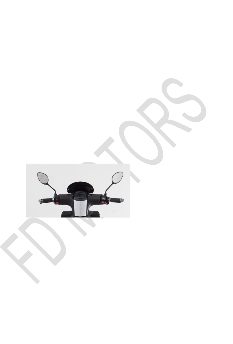
Assembly Instructions
Installing the mirrors
1. Mirrors can be easily fixed to the handle bars between the grips
and the brake handle.
2. Screw in the mirror clockwise. The mirror that goes on the left
controller is curved to the left and the mirror that goes on the right
controller curves to the right.
3. Secure mirror by tightening the bolt.
4. Clean and adjust both mirrors before you ride. Adjust each mirror
so you can see the lane behind you and as far as possible the
lane next to you. When the mirror is properly adjusted you can
see the edge of your arm and shoulder.
5. Charge the battery.
4

Technical Specification
F3 TECHNICAL DATA rear wheel side motor
Motor (W)
72V 1500W
Battery (V)(AH)
60V/35Ah Lithium battery
Communication System
CAN
Speed
speed
range
25KM/h
60KM
45KM/h
55KM
E-mark certificate No.
e13*168/2013*00689*00
Category
L1e-B
Charger Input Voltage
110V-230V
Charger
60V 5A
Charging Time
7-8 hours
Max.Load
261 Kg
Climibing Capacity
15%
Brakes (F/R)
disc/ disc with CBS
Brake Control
hand brake
Tire front/ rear
FR: 100/80-16 RR: 120/80-14
FR: 90/80-16 RR: 100/70-14
FR: 90/80-16 RR: 110/80-14
Wheel base
1435mm
Net Weight
111kg
Gorss Weight
125kg
Apparent size
1995*690*1115mm
5

F5 TECHNICAL DATA rear wheel side motor
Motor (W)
72V 3000W
Battery (V)(AH)
60V/45Ah Lithium battery
Communication System
CAN
Speed
speed
range
75KM/h
87 KM
E-mark certificate No.
e13*168/2013*00691*00
Category
L3e-A1
Charger Input Voltage
110V-230V
Charger
84V 10A
Charging Time
4.5 hours
Max.Load
265 Kg
Climibing Capacity
15%
Brakes (F/R)
disc/ disc with CBS
Brake Control
hand brake
Tire front/ rear
FR: 100/80-16 RR: 120/80-14
FR: 90/80-16 RR: 100/70-14
FR: 90/80-16 RR: 110/80-14
Wheel base
1435mm
Net Weight
115kg
Gorss Weight
129kg
Apparent size
1995*690*1115mm
6

Parts List
A. Head Lamp
B. Rear View Mirror
C. Throttle and Brake Lever
D. Front Turning Signal Lamp
E. Front Shock Absorber
F. Front Tire
G. Seat
H. Side Stand
I. Center Stand
J. Rear Side Motor
K. Rear Tire
L. Rear Reflector
M. Rear Shock Absorber
N. Rear Turning Signal Lamp
O. Rear Carrier
P. Battery Box
Q. Front disc Brake
R. Charging Socket
S. Rear Side Reflector
T. Taillight
7

Dashboard
8
Part
Item
Function
A
Left Indicator
Light is on when indicator is on +12V, green
color
B
Right Indicator
Light is on when indicator is on +12V, green
color
C
High beam
Light is on when high beam is on +12V, blue
color
D
MCU light
Light is on when there is any problem
amber color, with CAN function
E
Battery SOC
Total 10 grid
F
Three mode
SOC%; ODO; TRIP
G
Speedometer
Indicates speed

1. Battery SOC: the battery SOC% is controlled by CAN
communication.
LCD display
SOC(%) by CAN
1st segment light on
0~10
1st-2nd segment light on
11~20
1st-3rd segment light on
21~30
1st-4th segment light on
31~40
1st-5th segment light on
41~50
1st-6th segment light on
51~60
1st-7th segment light on
61~70
1st-8th segment light on
71~80
1st-9th segment light on
81~90
1st-10th segment light on
91~100
2. Select(H) button: (Unspecified, long press 3 seconds)
2.1 With CAN function, if there is an error code when displaying
ODO, long press Select(H) button to enter the display error code,
the error code is displayed in sequence, if the error is repaired, the
display mode will be exited; if it is not repaired, press Select(H)
button in 5S to exit the error display.
2.2 Adjust backlight brightness: Press Reset to adjust the brightness
of 4 level backlight (100%->75%->50%->25%->100%)
2.3 Press Reset and Select 3S simultaneously to switch metric
system
9

2.4 LCD characteristics:
1. Operating temperature: -30 ° C ~ +80 ° C
Display effect check method:
(1) When there is no backlight, there is no obvious base shadow at
the lower 30 degree angle; the lower 60 degree angle number is
easy to recognize.
(2) When there is no backlight, the vertical viewing angle should
not be dim.
2.5 Backlight color: blue (the backlight level is the brightness
saved in the last shutdown, the default backlight level is 100%)
3. MCU CAN
3.1.LCD SEGMENT OPERATION
3.2.BUZZER OPERATION:
After KEY is ON, if get MCU Stand by, the buzzer beeping
sound one time for 2 second. And the “FD motors”
appear. It means it ready to go.
4. BATTERY CAPACITY WARNING SEGMENT:
(When entering 0~20% SOC by can)
10

6. DTC (Diagnostic Trouble Code)
6-1. BATTERY
DTC Express
at the
speedometer
CAN_Messa
ge
Troubles Name
Battery
1
Battery
2
Byte
Bit
A10
F10
No data
BMS CAN Signal Failure
A11
F11
1
0
Charging Over Voltage
A12
F12
1
Charging Over Current
A13
F13
2
Discharging Under Voltage
A14
F14
3
Discharging Over Current
A15
F15
4
Short circuit
A16
F16
5
Charging Over Temperature
A17
F17
6
Discharging Over Temperature
A18
F18
7
Charging Under Temperature
A19
F19
2
0
Discharging Relay Failure
A20
F20
1
Charging Relay Failure
11

6-2. MCU
DTC Express
at the
speedometer
CAN_Message
Troubles Name
Byte
Bit
C10
No data
MCU CAN Signal Failure
C11
5
0
Identification error
C12
1
Over voltage
C13
2
Low voltage
C14
3
-
C15
4
Motor did not start
C16
5
Internal volts fault
C17
6
Over temperature
C18
7
Throttle error at power-up
C19
6
0
-
C20
6
1
Internal reset
C21
2
Throttle open or short
C22
3
-
C23
4
-
C24
5
-
C25
6
Motor over-temperature
C26
7
Hall Galvanometer sensor error
12

Ignition Key
Key Position
Description
On
Key cannot be taken out when power is on.
Off
Key can be taken out when power is off
Lock handle
bar
To prevent theft, turn the Handle Bar to the far left and turn
the key into the lock position. The key can be taken out
when handle bar is in the lock position.
When you want to change the oil. Please follow above picture.
It need 125 ml gear oil.
13

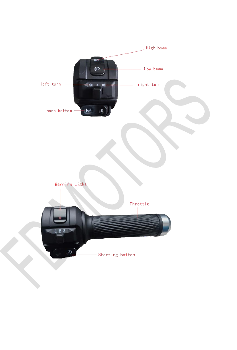
Left handle bar controls
Headlight Switch
High Beam –Push switch up
Low Beam –Push switch down
Signal Switch
Left Turn Signal –Slide switch to the left
Right Turn Signal –Slide switch to the right
Turning off Signal –Press central release button
Horn Button
Sounds Horn –Push the button on the left.
Left Brake Lever
(CBS)
When left Brake Handle is compressed the front/rear
wheel will brake together to a stop
Right handle bar controls
Right Brake Lever
When right brake handle is compressed the front
wheel will brake to a stop. To start, turn the throttle
counter clockwise.
Throttle
Turn throttle counter clockwise to increase speed.
Warning Light
1. Slide switch to the left , front and rear turn light
on.
2. Slide switch to the right, front and rear turn light
off.
Reverse
1. Press down (red button), the vehicle runs in
backward condition.
2. Press again (red button), the vehicle runs in
forward condition
14
15

Accelerating and Braking
Throttle Tips
1. Turn the key to the ‘ON’ position, Press the starting button and
you will hear a beeping sound. it means it is ready to go. And FD
motors will be appear on dashboard. .then you can start to run
the scooter.
2. To prevent losing control of the vehicle, please turn the Throttle
slowly until the speed increases.
3. Do not turn the Throttle until you are in the position to drive.
4. To stop, release the throttle and apply the front and rear brake
simultaneously.
5. To move, release the brakes and turn the Throttle gradually. The
motor makes a small electromagnetic noise when turning the
Throttle to start. This is normal.
6. Please, for your safety and security, take the key out when you
are not riding.
Braking Tips
1. For safety, this vehicle has a CBS system, when braking rear
brake lever, front and rear brake pump working together, when
braking front brake lever, only front brake pump working.
2. Less frequent sudden braking will increase range entirely. If
running under top speed, do not continually operate at full
throttle. Frequently releasing the throttle and running with
inertia will help to much increase your range. This motor has
good torque and the inertia momentum is enough to run some
distances without electric power.
16

Battery Gauge and Charging
Instructions
Grid
Description
10 grid
While riding, when the battery is fully charged the dashboard
shows 10grid.
1 grid
When the dashboard shows 2 grid, that means there is not
much power remain in battery. Ride at” Lower speed” you
can get more range and find the nearest charging point.
Charging
The battery for this vehicle can be charged on the vehicle or be
taken out, maintenance free D/C battery. The owner must use the
factory-supplied charger with an 110V (or 220V) outlet.
Turn off ignition switches while charging the battery. Plug one side
to an 110V (or 220V) outlet and the other into the charging plug on
the vehicle (located under the seat).
The charging time is 3.5hour(80%)for lithium battery. To fully
charge battery, charging time will be 5 hours.
To keep the battery in good condition, charge it if the SOC lower
than 10%. Please keep the battery in 50% to 60% of SOC.if the
vehicle has not been ridden for a long time .
Always check the battery SOC while you are riding and be sure
that it does not get too low too often.
17

Battery Longevit
The driver should, if possible, charge the scooter if the SOC lower
than 10% as this will help the battery’s life. The life of the Lithium
battery is 1000-1200 deep cycles (100% deep discharged).
Note: Pls stop the charging when the charging display is around
90%. It would be extended battery life .
Performance
A range of 70Mile (100km) has been recorded, yet the distance
and speed depend upon various elements of the rider’s style and
the road conditions. A 45km/h constant speed will ensure the
longest range but our figures include going flat out too. Other
factors include weather, vehicle condition, and battery charge.
Drivers must be cautious when driving on rough roads, in poor
weather, or when the battery charge is low.
After each trip, the driver should turn off the vehicle, take out
the key and charge the battery. This battery does not have memory
(i.e. you do not have to run it down completely to achieve a good
charge. On the contrary, regular charging will lengthen the life of
the battery) and can be charged at any time in the cycle of the
battery.
18

Maintenance
This electric motorbike represents a new generation of
environmentally friendly two-wheeled transportation. Therefore,
good maintenance will play a major role in keeping your vehicle in
good working condition and prolonging the life of the batteries.
Please follow these suggestions:
•To prevent rust always keep your vehicle dry and clean.
•
•Regularly check the front and rear tires, suspension and body
frame and all fasteners.
•When riding in rain do not go through deep puddles or muddy
areas; excessive water will cause the motor and other electrical
components to suffer undue harm.
•To prevent rust from forming on the vehicle, avoid parking your
vehicle in high humidity and corrosive areas.
•To avoid damage to the electrical parts of this vehicle,
especially the controller, do not park the vehicle in direct sunlight or
in heavy rain.
•Due to the complexity of the electronic manufacture of this
vehicle, customers should never attempt to take out any of the
parts, or attempt major maintenance without consulting the supplier
(this will invalidate the warranty).
•Never overload and ride the vehicle for an extended period of
time, prolonged use with excessive weight could cause serious
damage to the electronic and mechanical parts.
•Always check your vehicle and perform necessary routine
maintenance - tires, brakes, nuts and bolts.
•
•For your safety, perform routine maintenance on your vehicle.
This will lower the potential for damage.
19
This manual suits for next models
1
Table of contents
Other FD Motors Scooter manuals


