FDomes GLAMPING 20 User manual

ASSEMBLY
MANUAL
GLAMPING 20, 30, 40, 50


CONTENTS
FEET AND METAL BAND INSTALLATION GUIDE 7
PVC GROUND MEMBRANE INSTALLATION MANUAL 12
FRAMEWORK ASSEMBLY MANUAL 15
CAMPING DOOR ASSEMBLY MANUAL FG20 20
CAMPING DOOR ASSEMBLY MANUAL FG30/40/50 21
GLASS DOOR / ALUMINUM DOOR FRAME ASSEMBLY MANUAL FG30/40/50 23
OUTER MEMBRANE & TRANSPARENT FRONT ASSEMBLY GUIDE 26
PORTHOLE WINDOW ASSEMBLY MANUAL 29
SOLAR FAN ASSEMBLY MANUAL 30
STOVE & CHIMNEY ASSEMBLY MANUAL 31
INSULATION LINER ASSEMBLY MANUAL 33

4
LIST OF THE SUPPLIED FOR THE STRUCTURE ASSEMBLY:
NAME OF THE COMPONENT QUANTITY
PHOTO
A PIPE 30 PCS
B PIPE 40 PCS
C PIPE 70 PCS
D PIPE 10 PCS
METAL BAND 15 PCS
FOOT 15 PCS
M12/50 SCREWS FOR LEVEL 0 AND
FRONT TRANSPARENT WINDOW 18 PCS
WASHERS FOR M12 CONSTRUCTION’S
SCREWS 62+6 PCS
M12 SCREW NUTS 62+6 PCS
TO BUILD THE FG20, FG30, FG30, FG40, FG50 YOU WILL NEED:
• 4 people,
• a ladder of a minimum 4 m height,
• a drill,
• a 19 mm automatic wrench (impact gun),
• an 8mm and a 5 mm Allen key,
• a hammer,
• 3 ropes - 15 - 20 m long each,
• a protective ground sheet at least: 6 x 4 m
(to unfold the membrane onto, before pulling
it onto the metal framework. It will protect
the membrane from getting dirty on bare ground).

5
OPTIONAL:
NAME OF THE COMPONENT QUANTITY
PHOTO
SCREWS, ANCHORS OR PINS TO FIX
THE FEET (OPTIONAL, DEPENDING
ON THE DOME CUSTOMIZATION)
SCREWS, ANCHORS OR PINS
TO FIX THE FEET (OPTIONAL,
DEPENDING ON THE DOME
CUSTOMIZATION)
WASHERS FOR FEET MOUNTING
BOLTS (OPTIONAL, WHEN FEET
SCREWS APPLIED)
60 PCS
M12/60 SCREWS FOR THE
STRUCTURES WITHOUT
INSULATION
50 PCS
M12/70 SCREWS FOR THE
STRUCTURES WITH INSULATION
50 PCS
-
LIST OF THE SUPPLIED COMPONENTS FOR THE OUTER MEMBRANE ASSEMBLY:
NAME OF THE ELEMENT QUANTITY PHOTO
MEMBRANE 1 -
BUNGEE CORD 15
HOOKS FOR THE MEMBRANE
AND METAL BANDS
FG20/30=140
FG40=160 G50=190
TRANSPARENT FRONT 1 -
PLEXIGLASS PORTHOLE WINDOW 3 OR 5 DEPENDING ON THE
ORDER -
MAGNETS - FG20/30 CAMPING
DOOR
29 PIECES (500 MM) + 1 PIECE
300 MM
MAGNETS - FG30 ALUMINIUM
GLASS DOOR 28 PIECES (500 MM)
MAGNETS - FG40 CAMPING DOOR 29 PIECES (500 MM) + 15 PIECES
(300 MM)
MAGNETS - FG40 ALUMINIUM
GLASS DOOR
28 PIECES (500 MM) + 14 PIECES
(300 MM)
MAGNETS - FG50 CAMPING DOOR 43 PIECES (500 MM) + 1 PIECE
(300 MM)
MAGNETS - FG50 ALUMINIUM
GLASS DOOR 42 PIECES (500 MM)
MM = MILLIMETER
6
LIST OF THE SUPPLIED COMPONENTS FOR THE PVC FLOOR ASSEMBLY:
NAME OF THE ELEMENT QUANTITY PHOTO
BLACK PCV MEMBRANE 1
(HARD) VELCRO TO STICK
ON THE METAL BANDS
G20 = 16 M G30 = 19 M
G40=22 M G50 = 25 M
(SOFT) VELCRO TO STICK ON THE
PCV MEMBRANE
G20 = 16 M G30 = 19 M
G40 = 22 M G50 = 25 M
MM = MILLIMETER
LIST OF THE SUPPLIED COMPONENTS FOR THE CAMPING DOOR ASSEMBLY:
NAME OF THE ELEMENT QUANTITY
DOOR WITH A FRAME 1
AR PIPE FG20/30/40/50 1
AL PIPE FG30/40/50/80 1
BR PIPE FG20/30/40/50 1
BL PIPE FG20/30/40/50 1
CR PIPE FG20/30/40/50 1
CL PIPE FG20/30/40/50 1
DR PIPE FG20/30/40/50 1
DL PIPE FG20/30/40/50 1
ER PIPE FG20 1
EL PIPE FG20 1
WASHERS AND NUTS FOR FASTENING THE AR, AL, BR,
BL, CR, CL, DR, DL PIPES TO THE DOOR FRAME FG30/40/50 = 8PCS, G20 = 12PCS
SCREWS FOR ATTACHING THE DOOR FRAME
TO THE
METAL BAND 2
LIST OF THE COMPONENTS SUPPLIED FOR THE GLASS DOOR ASSEMBLY:
NAME OF THE ELEMENT QUANTITY
GLASS DOOR WITH ALUMINIUM FRAME 1
K PIPE FG40/50 2
L PIPE FG30/40/50 2
CLAMP FG30 (CLAMP FOR FG30) 2

7
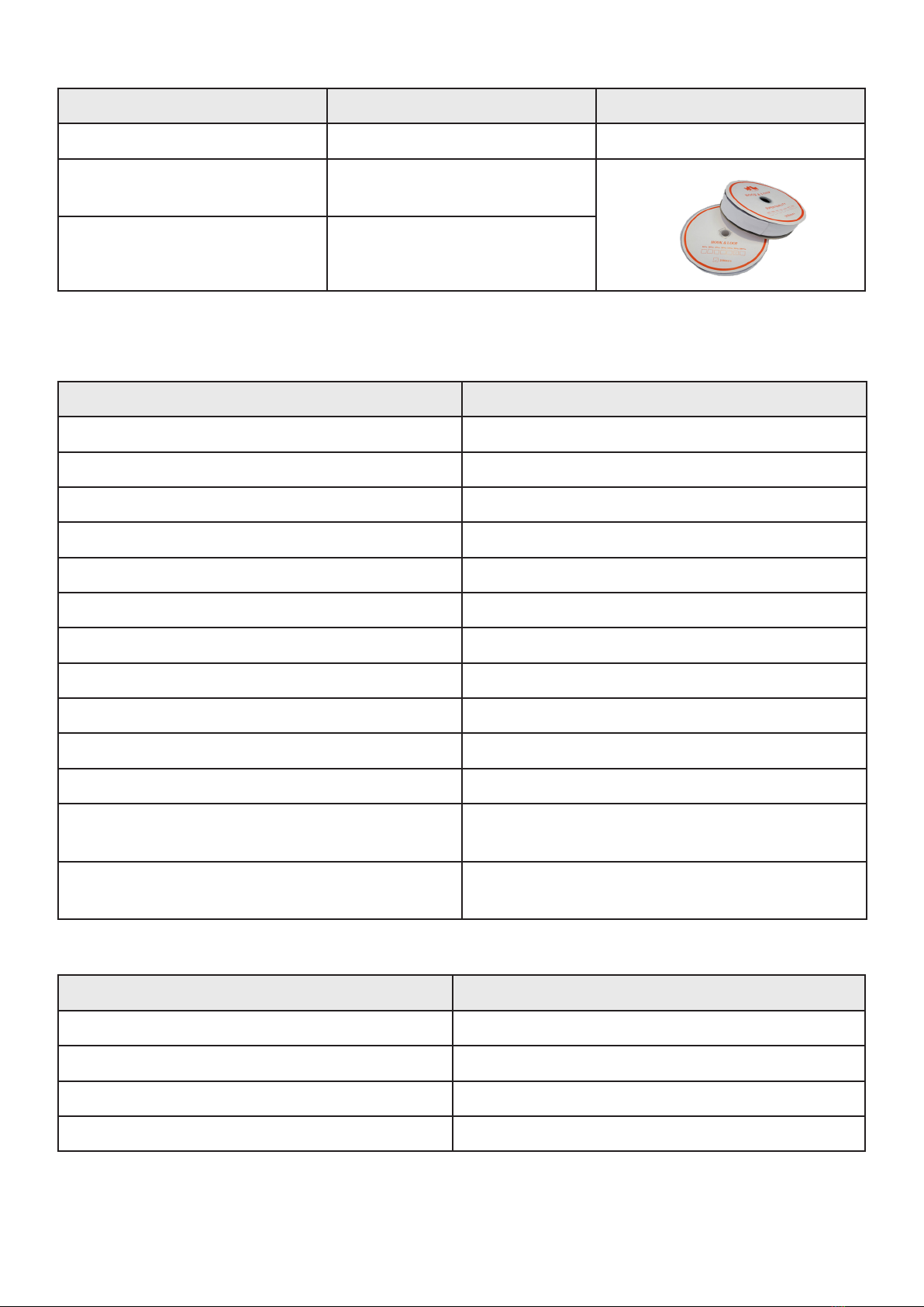
FEET AND METAL BAND INSTALLATION GUIDE
STEP 1
Mark the spot where the center of the dome is to be. Draw a circle with a radius consistent with the table below.
It is best to make a permanent mark where the center is (with a marker or drive in a screw) so that you know which
spot to go back to when double checking your measurements.
GLAMPING FG20 R= 2480 MM
GLAMPING FG30 R= 2965 MM
GLAMPING FG40 R= 3455 MM
GLAMPING FG50 R= 3950 MM
MM = MILLIMETER
What is needed:
• 15x feet
• 15x metal bands
• 15x nuts
• 30x washers
• 15x bolts
• 30x Anchor Bolts and washers
• Measuring tape, cord, chalk/marker (not included
in FDomes Delivery)
Drawing 1
Marked circle and a corresponding radius.

8
STEP 2
Place the feet and metal bands on the perimeter of the circle which you have just drawn. Define the positions
of the door and the transparent front window.
Radius of the dome Centre of the dome
Mid Line of the dome
P4 Entrance
P3 Entrance
Chalk line drawn
on the platform /
dome perimeter
Transparent front
Drawing 3
Feet and baseplates
Drawing 2
Reference point for radius measurement

9
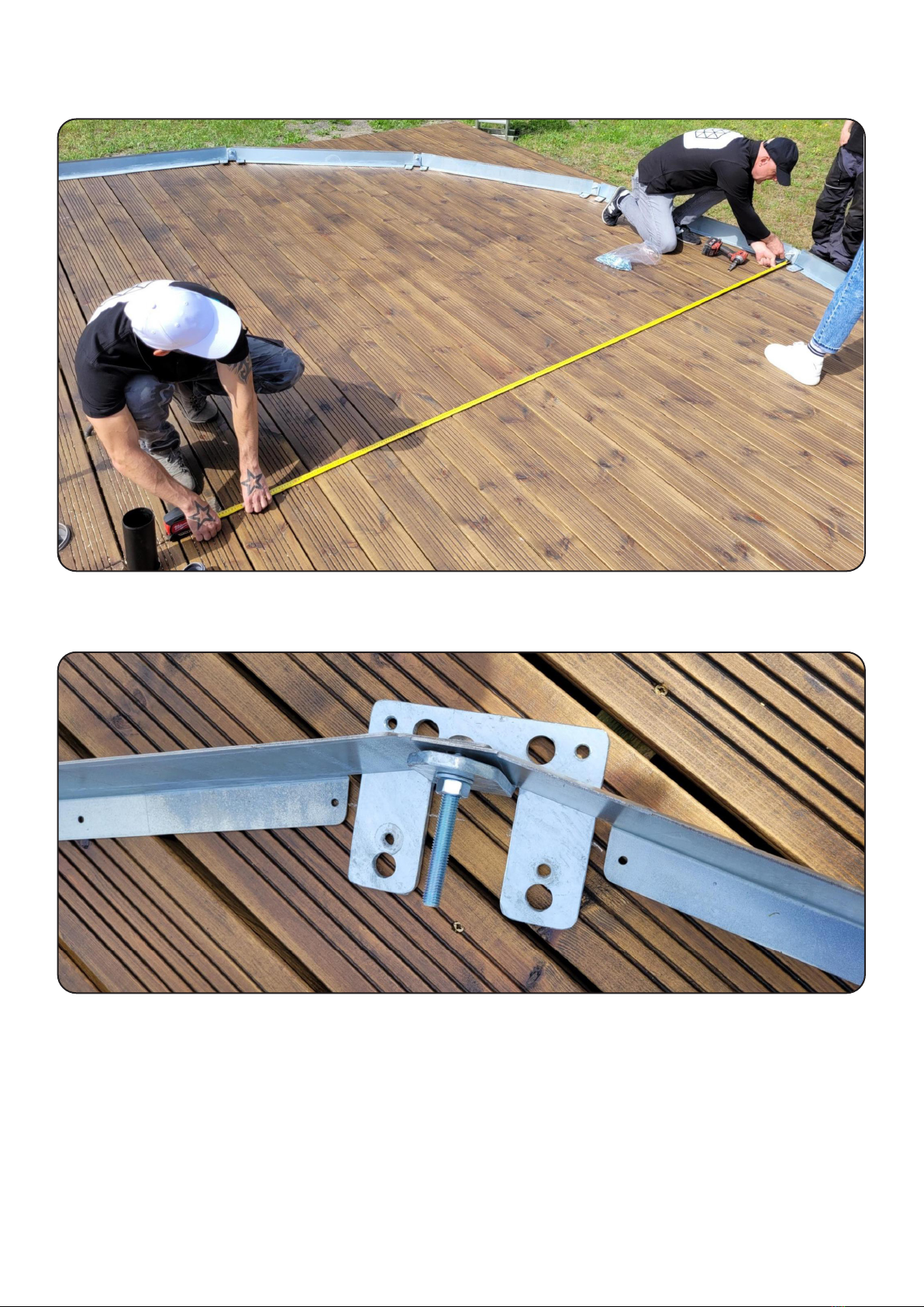
STEP 3:
Screw the feet and the metal bands together, placing them precisely along the previously drawn perimeter line. Align
the plates together with the foot, push the bolt in from the outside. From the inside, place the washer first and the nut
second. Loosely screw on the nut.
NOTE:
Place the ends of metal bands on the external face of the vertical part of the foot.
10
STEP 4:
Double check the positioning and the radius. Readjust the feet and metal bands.
STEP 5:
Tighten the nuts on the bolts which you have just installed.

11
STEP 6:
Using the anchor bolts (if ordered) fix the feet to the deck / concrete slab. Pick two of four available holes and
drive the screws into the deck / concrete slabs (two screws per one foot).
CONGRATULATIONS!
YOU ARE DONE WITH THE DOME’S FEET
AND METAL BAND ASSEMBLY!
12
PVC GROUND MEMBRANE INSTALLATION MANUAL
NOTE:
By now, you should have your dome’s legs and base plates in position and screwed together, all along
the previously drawn perimeter of the dome. If you purchased the dome together with the Interior Modules, you
need to install the PVC Ground Membrane now, as you will be placing the modules on top of this membrane.
If you purchased the dome as a stand-alone unit without our Interior Modules, you can install the PVC Ground
Membrane once the whole dome is constructed.
NOTE:
The diameter of the PVC Ground Membrane is larger than the diameter of your dome’s footprint.
NOTE:
If you didn’t purchase the Interior Modules, steps 4 and 5 do not apply.
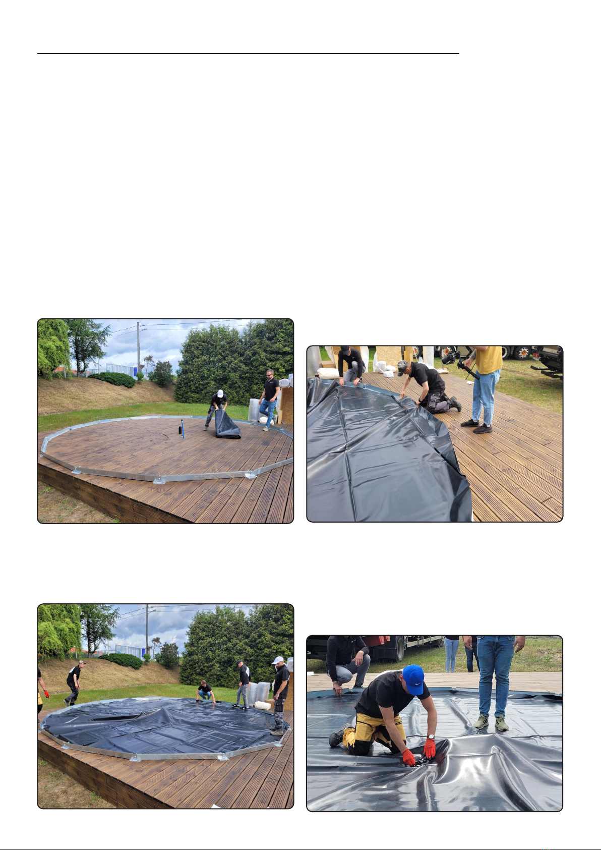
STEP 1:
Unfold the PVC Ground membrane within the perimeter
of the dome.
STEP 2:
Position the membrane evenly across the whole footprint
of the dome following its shape. It is produced in a way
which resembles the shape of the dome therefore you
may need to rotate it.
STEP 4:
If you will be installing the FDomes Interior Modules,
carefully pierce holes to let the media connections
through (water, sewage, electricity, ventilation). Make
sure that your openings in the membrane are just big
enough to let the connections through.
STEP 3:
Flip any excess material over the edges of the base plates
- make sure it is evenly distributed around the perimeter of
the dome.
13
STEP 5:
Take out your connections from underneath the membrane.
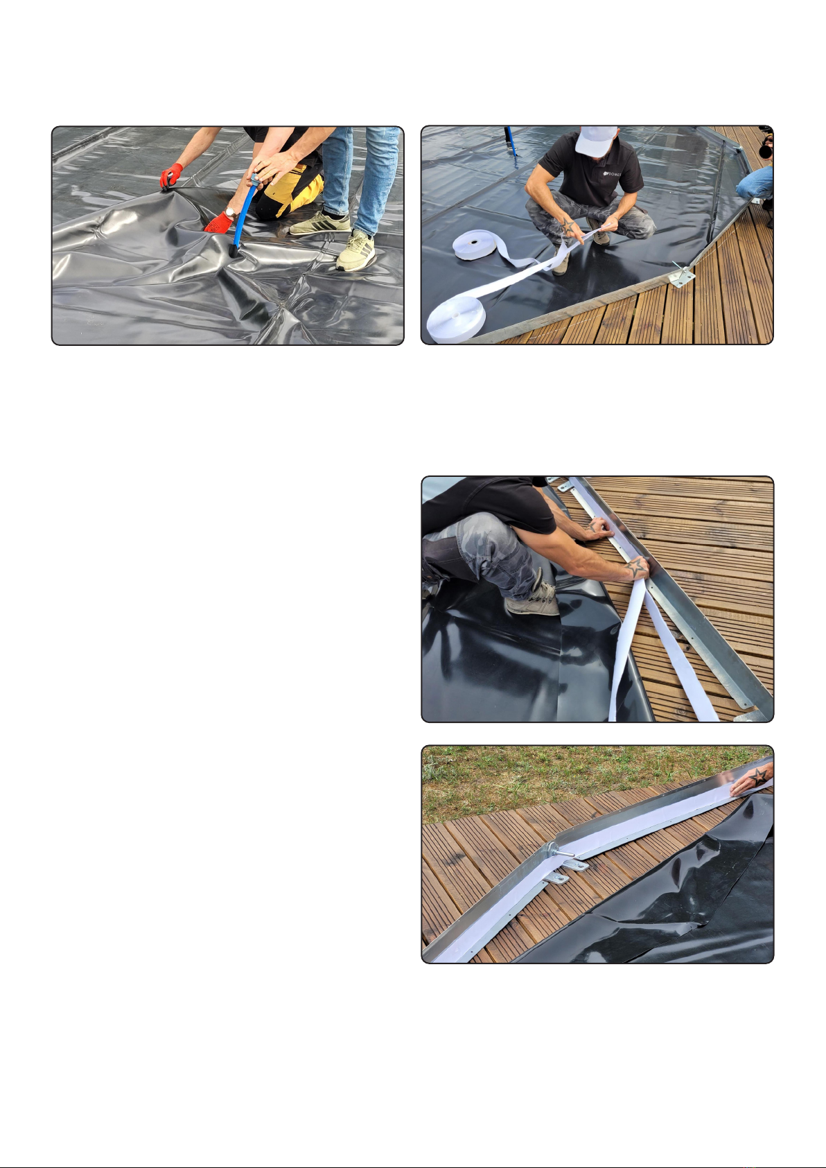
STEP 6:
Connect the male (hook) and the female (loop) sides
of the velcro tape together.
STEP 7:
While standing on the inside of the dome’s perimeter,
gently flip the excess membrane o the legs and base
plates, fully exposing them.
STEP 8:
Peel the paper o from one side of the now connected
velcro tape and place it along the bottom of the base
plates, on the vertical section facing the inside of
the dome, all along its perimeter.

14
STEP 10:
Wherever the bolts are an obstruction, cut through
the membrane to let them through.
STEP 11:
Leave any excess membrane on, you will be able to trim
it later if it can not be hidden and becomes a visual
problem.
STEP 9:
Peel the paper off from the other side of the velcro tape
and glue the membrane right on.
NOTE:
There is no need to pull the membrane tight, especially
when you are installing it in warm climates. As soon as
the temperature drops, the material will shrink in size,
which is perfectly normal.

15
FRAMEWORK ASSEMBLY MANUAL
METAL BAND
METAL BAND
METAL BAND
METAL BAND
Drawing 4
Assembly diagram (Overwiev)
Drawing 5
Dome framework map
16
STEP 1
Build the fist level of the framework according to the map presented below. Remember to unscrew the nuts
of the screws connecting the feet with the metal bands. It will enable you to install the pipes which are
necessary to build the fist level of the framework.
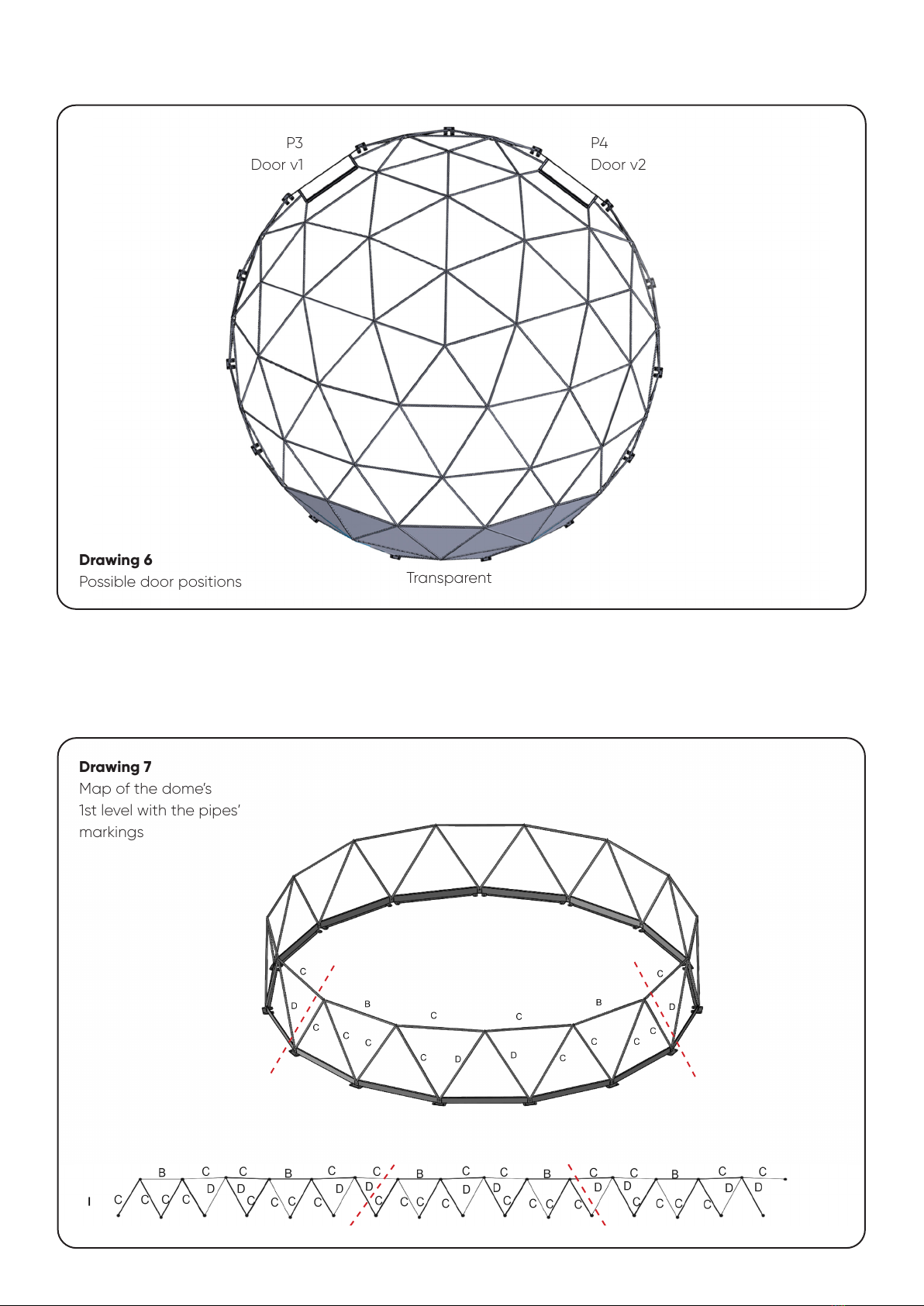
Drawing 7
Map of the dome’s
1st level with the pipes’
markings
The drawings below show a layout of the framework and the possible positions of the door in relation
to the transparent front window.
P4
Door v2
P3
Door v1
Transparent
Drawing 6
Possible door positions

17
STEP 2
Build the second level of the dome according to the map below.
Drawing 10
Map of the framework’s
2nd level with the pipes’
markings
Drawing 9
Finished knot - view from
the inside to the outside
Drawing 8
Finished knot - view from
the outside to the inside

18
STEP 4
Build the fourth level of the framework according to the map below.
Drawing 14
Map of the dome’s 4th level
with the pipes’ markings
STEP 3
Build the third level of the framework according to the map below.
Drawing 11
Map of the framework’s
3rd level with the pipes’
markings
19
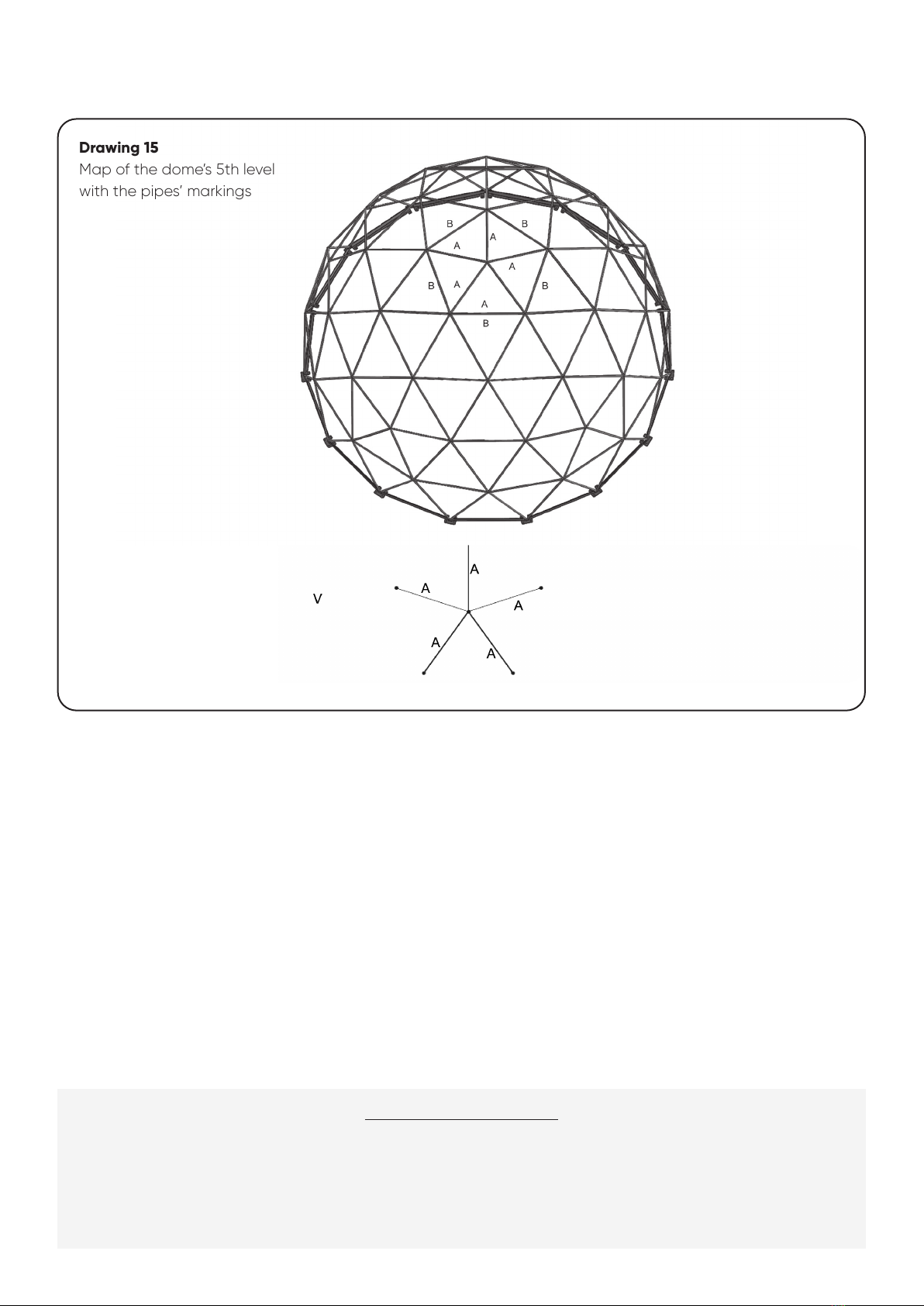
STEP 5
Build the fith level of the framework according to the map below.
Drawing 15
Map of the dome’s 5th level
with the pipes’ markings
CONGRATULATIONS!
YOU HAVE JUST FINISHED
BUILDING THE DOME’S
FRAMEWORK :)

20
CAMPING DOOR ASSEMBLY MANUAL FG20
STEP 1
Remove the C-C-D-D-C-C, B-A-B-C-C-B-A-B-B pipes as presented in the below drawing.
NOTE:
The dome might loose it's shape slightly - don't worry. It will all come back together once the doors are in place.
P3 / P4
Drawing 16
Pipes to be removed
STEP 2
Insert the door frame with the camping door and attach it to the framework using the pipes as presented
in the drawing 11. The pipes are adjustable which makes it easy to level the door.
Drawing 17
Scheme of inserting
the camping door into
the dome’s framework
This manual suits for next models
4
Table of contents
Popular Outdoor Furnishing manuals by other brands


Nuu Garden
Nuu Garden CT002 instruction manual

Backyard Discovery
Backyard Discovery STRATFORD Assembly manual

Lemeks
Lemeks Palmako PA-3333 Assembly, installation and maintenance manual

TreeTop Products
TreeTop Products BC2315 quick start guide

Outsider
Outsider PLATEAU 205 Mounting guide

Arboria
Arboria VISTA ARBOR Assembly instructions


