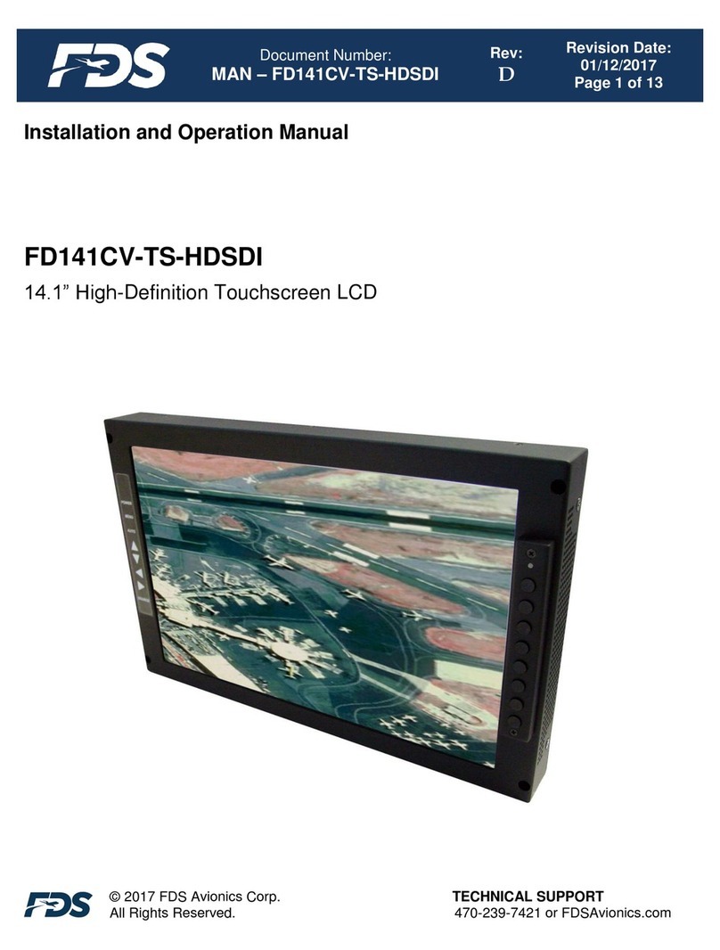
FDS FD215CV-C-TS User manual

Document Number:
MAN –FD215CV-C-TS (-1)
Rev:
B
Revision Date:
01/10/2017
Page 1 of 16
©2017 FDS Avionics Corp.
All Rights Reserved.
TECHNICAL SUPPORT
470-239-7421 or FDSAvionics.com
Installation and Operation Manual
FD215CV-C-TS
FD215CV-C-TS-1
21.5” LCD Touchscreen Display

Document Number:
MAN –FD215CV-C-TS (-1)
Rev:
B
Revision Date:
01/10/2017
Page 2 of 16
©2017 FDS Avionics Corp.
All Rights Reserved.
TECHNICAL SUPPORT
470-239-7421 or FDSAvionics.com
Specifications
FD215CV-C-TS
FD215CV-C-TS-1
Display
Panel Technology
21.5” TFT Color LCD
21.5” TFT Color LCD
Color
16.7 Million Colors
16.7 Million Colors
Native Resolution
Refresh Rate
1920 x 1080
1920 x 1080
Touchscreen
Capacitive Touchscreen Glass
Capacitive Touchscreen Glass
Touchscreen Control
USB
RS-232
Brightness
300 cd/m²
300 cd/m²
Aspect Ratio
19:9
19:9
Viewing Angle
170º Horizontally
160º Vertically
170º Horizontally
160º Vertically
Power
Power
28V DC @ 3 Amps
28V DC @ 2 Amps
Inrush Current
18.0 Amps @2.0 µS
4.0 Amps @ 2mS
2.0 Amp Steady State @ 3.5mS
18.0 Amps @2.0 µS
4.0 Amps @ 2mS
2.0 Amp Steady State @ 3.5mS
Environmental
Conditions
Operating Temperatures
5º - 45º C
5º - 45º C
Dimensions
External
20.0”(W) x 13.25”(H) x 1.76” (D)
20.0”(W) x 13.25”(H) x 1.76” (D)
Active Display Area
18.64”(W) x 10.43” (H)
18.64”(W) x 10.43” (H)
Weight
10 lbs. 13 oz.
10 lbs. 13 oz.
Materials
Aluminum
Aluminum
Features
Menu Control
On Screen Display Menu
On Screen Display Menu
Qualified
Testing
RTCA DO-160
160G Sec 21 Cat B –Emissions

Document Number:
MAN –FD215CV-C-TS (-1)
Rev:
B
Revision Date:
01/10/2017
Page 3 of 16
©2017 FDS Avionics Corp.
All Rights Reserved.
TECHNICAL SUPPORT
470-239-7421 or FDSAvionics.com
Connectivity
* NTSC or PAL
** Touchscreen Controller

Document Number:
MAN –FD215CV-C-TS (-1)
Rev:
B
Revision Date:
01/10/2017
Page 4 of 16
©2017 FDS Avionics Corp.
All Rights Reserved.
TECHNICAL SUPPORT
470-239-7421 or FDSAvionics.com
Table of Contents
General Information...................................................................................................... 5
Front View...................................................................................................................... 5
Additional Information.................................................................................................. 5
Installation Instructions................................................................................................ 6
Power and Ground Wiring............................................................................................ 6
VGA Wiring.................................................................................................................... 6
Pinouts...................................................................................................................... 7-10
Operation Instructions................................................................................................ 11
Button Control............................................................................................................. 11
Touchscreen Driver .................................................................................................... 12
Technical Drawing ...................................................................................................... 13
Technical Support....................................................................................................... 14
Instructions for Continued Airworthiness ................................................................ 14
Warranty ...................................................................................................................... 15
Log of Revisions......................................................................................................... 16

Document Number:
MAN –FD215CV-C-TS (-1)
Rev:
B
Revision Date:
01/10/2017
Page 5 of 16
©2017 FDS Avionics Corp.
All Rights Reserved.
TECHNICAL SUPPORT
470-239-7421 or FDSAvionics.com
General Information
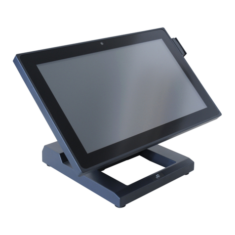
The FD215CV-C-TS(-1) is a touchscreen enabled, special mission, high resolution,
panel mounted 21.5” widescreen LCD.
Front View
Additional Information
The LCD features include:
Five video source inputs are available to include:
1. HD-SDI (for HD camera inputs)
2. DVI
3. VGA (for computer graphics, i.e.; moving maps)
4. S-Video (via BNC connectors for Y and C components)
5. Composite
Dual USB 2.0 powered ports are provided for connection to mission computers for
quick and easy access to files via thumb drive. Each port also supplies up to 500mA to
power external devices.
Bezel buttons on front of display for operational convenience of OSD.
HD-SDI loop through for output to a HD-DVR or other displays.

Document Number:
MAN –FD215CV-C-TS (-1)
Rev:
B
Revision Date:
01/10/2017
Page 6 of 16
©2017 FDS Avionics Corp.
All Rights Reserved.
TECHNICAL SUPPORT
470-239-7421 or FDSAvionics.com
Installation Instructions
Use (6) 8-32 Machine screws. See the technical drawing on page 13 for mounting locations
and details.
All cabin equipment, such as the FD215CV-C-TS(-1), should be installed on a non-essential
bus and have a dedicated circuit breaker. It is a requirement that a switch be installed in the
cockpit so that the pilot can de-energize the system should it become necessary.
Power and Ground Wiring
The rated current of the equipment and associated voltage drop should be taken into
consideration when selecting wire gauge. The following example is based on an install with a
28VDC power system, 1.5 amp equipment load and a total of 50 feet of wire between the
circuit breaker, monitor and ground.
Example: 22awg wire has 16.2 Ohms per 1000 feet, this equates to .81 Ohms for 50 feet. 1.5
Amp of current on .81 Ohms will drop 1.22 Volts.
Resistance of Wire Type M22759/16-**
(** = Gauge)
Gauge (AWG)
OHMS/1000’
24
26.20
22
16.20
20
9.88
16
4.81
12
2.02
10
1.26
8
.701
Also, use short heavy gauge wire and a clean tight connection for ground.
It is the installer's responsibility to understand the product's requirements in order to install the
product in compliance with industry standards and safety.
VGA Wiring
The FD215CV-C-TS(-1) uses standard VGA cables for input.

Document Number:
MAN –FD215CV-C-TS (-1)
Rev:
B
Revision Date:
01/10/2017
Page 7 of 16
©2017 FDS Avionics Corp.
All Rights Reserved.
TECHNICAL SUPPORT
470-239-7421 or FDSAvionics.com
Pinouts for FD215CV-C-TS (-1)
Pinout for 28V PWR–D38999 connector (supplied)
Mating Connector P/N: D38999/26FB5SA or Equivalent
Crimp Contacts P/N: M39029/56-351 or Equivalent
MATING FACE
Pin
Number
Description
A
28VDC Power
B
28VDC Power
C
28VDC Ground
D
28VDC Ground
E
N/C

Document Number:
MAN –FD215CV-C-TS (-1)
Rev:
B
Revision Date:
01/10/2017
Page 8 of 16
©2017 FDS Avionics Corp.
All Rights Reserved.
TECHNICAL SUPPORT
470-239-7421 or FDSAvionics.com
Pinout for Touchscreen Control (DB-9F)
Connector P/N: M24308/2-281 or Equivalent
Crimp Contacts P/N: M39029/63-368 or Equivalent
Pin
Description
FD215CV-C-TS
FD215CV-C-TS-1
1
+5V POWER (FROM USB SOURCE)
N/C
2
DATA (DN) DIFFERENTIAL PAIR
RS-232 TX (Connect to Pin 2 on STD DB9
COM Port)
3
DATA (DP) DIFFERENTIAL PAIR
RS-232 RX (Connect to Pin 3 on STD DB9
COM Port)
4
POWER RETURN
N/C
5
CHASSIS GROUND
RS-232 GND (Connect to Pin 5 on STD DB9
COM Port)
6
N/C
N/C
7
N/C
N/C
8
N/C
N/C
9
N/C
N/C

Document Number:
MAN –FD215CV-C-TS (-1)
Rev:
B
Revision Date:
01/10/2017
Page 9 of 16
©2017 FDS Avionics Corp.
All Rights Reserved.
TECHNICAL SUPPORT
470-239-7421 or FDSAvionics.com
Pin out for HD-SDI Input
(Standard BNC –75 OHM) - Supplied
Pin
Description
Center
Video Signal
Shell
Video Return
Pin out for HD-SDI Output
(Standard BNC –75 OHM) - Supplied
Pin
Description
Center
Video Signal
Shell
Video Return
Pin out for S-Video (Luminance - Y Component)
(Standard BNC –75 OHM) - Supplied
Pin
Description
Center
Y Signal
Shell
Y Return
Pin out for S-Video (Chrominance - C Component)
(Standard BNC –75 OHM) - Supplied
Pin
Description
Center
C Signal
Shell
C Return
Pin out for Composite Video
(Standard BNC –75 OHM) - Supplied
Pin
Description
Center
Video Signal
Shell
Video Return

Document Number:
MAN –FD215CV-C-TS (-1)
Rev:
B
Revision Date:
01/10/2017
Page 10 of 16
©2017 FDS Avionics Corp.
All Rights Reserved.
TECHNICAL SUPPORT
470-239-7421 or FDSAvionics.com
Pin out for DVI-D
Accepts a standard DVI-D (Single Link) male connector (supplied)
View into mounted receptacle
Pin
Number
Description
1
TMDS data 2-
2
TMDS data 2+
3
TMDS data 2 shield
4
N/C
5
N/C
6
DDC clock
7
DDC data
8
N/C
9
TMDS data 1-
10
TMDS data 1+
11
TMDS data 1 shield
12
N/C
13
N/C
14
+5 V
15
Ground
16
Hot plug detect
17
TMDS data 0-
18
TMDS data 0+
19
TMDS data 0 shield
20
N/C
21
N/C
22
TMDS clock shield
23
TMDS clock+
24
TMDS clock-
C1
N/C
C2
N/C
C3
N/C
C4
N/C
C5
N/C

Document Number:
MAN –FD215CV-C-TS (-1)
Rev:
B
Revision Date:
01/10/2017
Page 11 of 16
©2017 FDS Avionics Corp.
All Rights Reserved.
TECHNICAL SUPPORT
470-239-7421 or FDSAvionics.com
Operation Instructions
The FD215CV-C-TS(-1) is continuously on but can be de-energized by removing power
from the video system. No pilot or aircrew action is necessary during flight or ground
operation.
The operator will be able to change the video output from the FD215CV-C-TS(-1) using
the video source select button on the display.
When applying 28VDC power, the display will turn on and look for a valid input on the
last known source. If no input is found, the display will go to standby mode. Pressing
the Source button will rotate through available video inputs.
Button Controls
Located on the front of the FD215CV-C-TS(-1) are 8 buttons:
BUTTON
DESCRIPTION
PWR
Turns ON/OFF the system.
MENU
Activates the OSD menu for the monitor settings or goes
to previous menu.
AUTO
Auto-adjustment in RGB.
Moves the highlight icon down through menu options.
Moves the highlight icon up through menu options.
Decreases the adjustment of the selected function.
Increases the adjustment of the selected function.
SCE
Cycles through available input sources.

Document Number:
MAN –FD215CV-C-TS (-1)
Rev:
B
Revision Date:
01/10/2017
Page 12 of 16
©2017 FDS Avionics Corp.
All Rights Reserved.
TECHNICAL SUPPORT
470-239-7421 or FDSAvionics.com
Touchscreen Driver
The FD215CV-C-TS and FD215CV-C-TS-1 utilize a touchscreen controller
manufactured by 3M. The touchscreen driver is supplied by 3M and FDS Avionics
Corp. recommends downloading the latest version of the driver during the installation of
the FD215CV-C-TS/-1, at the following address:
http://solutions.3m.com/wps/portal/3M/en_US/Electronics_NA/Electronics/Tools_Suppo
rt/Support/
Follow the web address above and select the operating system depending on the
platform that will be connected to the FD215CV-C-TS (-1). Any of the MT7 drivers
should work for either the FD215CV-C-TS or FD215CV-C-TS-1 as long as the correct
operating system was selected.
Make sure to follow the installation instructions and plug in the touchscreen controller
when asked by the installation software. The FD215CV-C-TS-1 driver installation may
require a reboot of the system platform after installation for the RS-232 monitoring
service to start.
The MT7 Software Users Guide can also be found at the same location as the driver
download. This document has detailed instructions on how to use and setup the MT7
touch screen software. Topics include: Calibration, Linearization, Changing the Touch
Down/Touch Up events, changing the audible beep and multi-display configuration.

Document Number:
MAN –FD215CV-C-TS (-1)
Rev:
B
Revision Date:
01/10/2017
Page 13 of 16
©2017 FDS Avionics Corp.
All Rights Reserved.
TECHNICAL SUPPORT
470-239-7421 or FDSAvionics.com
Technical Drawing

Document Number:
MAN –FD215CV-C-TS (-1)
Rev:
B
Revision Date:
01/10/2017
Page 14 of 16
©2017 FDS Avionics Corp.
All Rights Reserved.
TECHNICAL SUPPORT
470-239-7421 or FDSAvionics.com
Technical Support
Should you have any questions concerning this product or other FDS Avionics Corp.
products, please contact our Product Support representatives at (470) 239-7421.
FDS Avionics Corp.
6435 Shiloh Road
Alpharetta, GA 30005
Phone: 470-239-7400
Fax: 470-239-7439
Email: [email protected]
For further product information, technical data and sample wiring diagrams, please click
on the Dealers section of our web site at www.FDSAvionics.com
Instructions for Continued Airworthiness
The FD215CV-C-TS(1) is designed not to require regular general maintenance.

Document Number:
MAN –FD215CV-C-TS (-1)
Rev:
B
Revision Date:
01/10/2017
Page 15 of 16
©2017 FDS Avionics Corp.
All Rights Reserved.
TECHNICAL SUPPORT
470-239-7421 or FDSAvionics.com
Warranty Information
All FDS Avionics Corp. (FDS) products are warranted to be free from material or manufacturing defects for
a period of 24 months from the date of shipment for General Aviation customers or 12 months from the date
of shipment for Government/Special Mission customers. Any material or repair workmanship for in warranty
repair service will be specifically warranted for 90 days or the remainder of the original warranty period,
whichever is longer. If the original warranty period has expired, the 90 day repair warranty is limited to the
material and workmanship specific to the repair activity completed.
The following conditions are exclusions to warranty coverage:
1. Labor costs associated with installation, removal or reinstallation of any product.
2. Damage to or malfunction caused by any unauthorized alteration made to the product.
3. Resolving signal quality issues caused by externally generated noise introduced by aircraft electrical
systems or other components connected to any FDS product.
4. Any malfunction caused by improper installation or connection to aircraft wiring, industry standard
cabin management/ inflight entertainment systems, or third party commercial equipment not
specifically identified as compatible with FDS products.
5. Any malfunction caused by installation that does not conform to precautions associated with
operating environments listed in the operating manual or consistent with industry best practices
such as; high temperature, adequate ventilation, high humidity, high dust, or power surges.
6. Cosmetic damage or damage to internal components caused by installation or removal, failure to
follow installation or operating instructions, or any neglect or misuse of the product.
7. Any product that is returned for service with a broken tamper evident seal, indicating tampering or
improper handling of the product by an unauthorized person. Violation of product tamper evident
seals or modification of factory installed serial and PMA labels voids any warranty, either expressed
or implied.
The FDS technical support team is available to provide distance troubleshooting support during business
hours (8:00am to 5:00pm EST) Monday through Friday at (470) 239-7421.
Many repair requests can be resolved through distance support and may not require return of merchandise
to the factory. If a product must be returned to the factory for repair, an RMA number will be issued as
directed by the technical support team and communicated by the repair coordinator.
Upon request by the customer, FDS may send a service technician onsite to repair any non-PMA products.
The travel expenses incurred to include transportation, lodging and meals along with the technician’s hourly
rate shall be payable by the customer in accordance with FDS’ applicable rates and procedures.
FDS Avionics Corp. will, upon receipt of returned merchandise, remanufacture or replace the unit at our
discretion and return the product by Ground Return Shipping. Express return shipment will be the
responsibility of the sender.
This warranty is not transferable.
Any implied warranties expire at the express limited warranty expiration date. FDS shall not be held liable
for any indirect, special, punitive, incidental or consequential damages.
Some states do not allow limitation on the length of an implied warranty. In such states, the exclusions or
limitations of this limited warranty may not apply.

Document Number:
MAN –FD215CV-C-TS (-1)
Rev:
B
Revision Date:
01/10/2017
Page 16 of 16
©2017 FDS Avionics Corp.
All Rights Reserved.
TECHNICAL SUPPORT
470-239-7421 or FDSAvionics.com
Log of Revisions
Rev
Date
Page
Description
A
12/06/2012
All
Initial Release
B
10/06/2015
All
Added provision for FD215CV-C-TS-1 RS232 Version.
Updated Format, Warranty, Specifications
B
1/10/2017
All
Changed Company Name and Formatting –No Revision
Change Necessary.
This manual suits for next models
1
Table of contents
Other FDS Touchscreen manuals
Popular Touchscreen manuals by other brands

Sanuvox
Sanuvox Bio Smart Screen instruction manual
Jensen
Jensen CAR710W quick start guide
Eaton
Eaton iLumin Plus TSE80-B installation instructions

Seedsware
Seedsware EMG Series Product specification

RAB Lighting
RAB Lighting Lightcloud Touch quick start guide
Johnson Controls
Johnson Controls Tyco HS2TCHP E user manual
