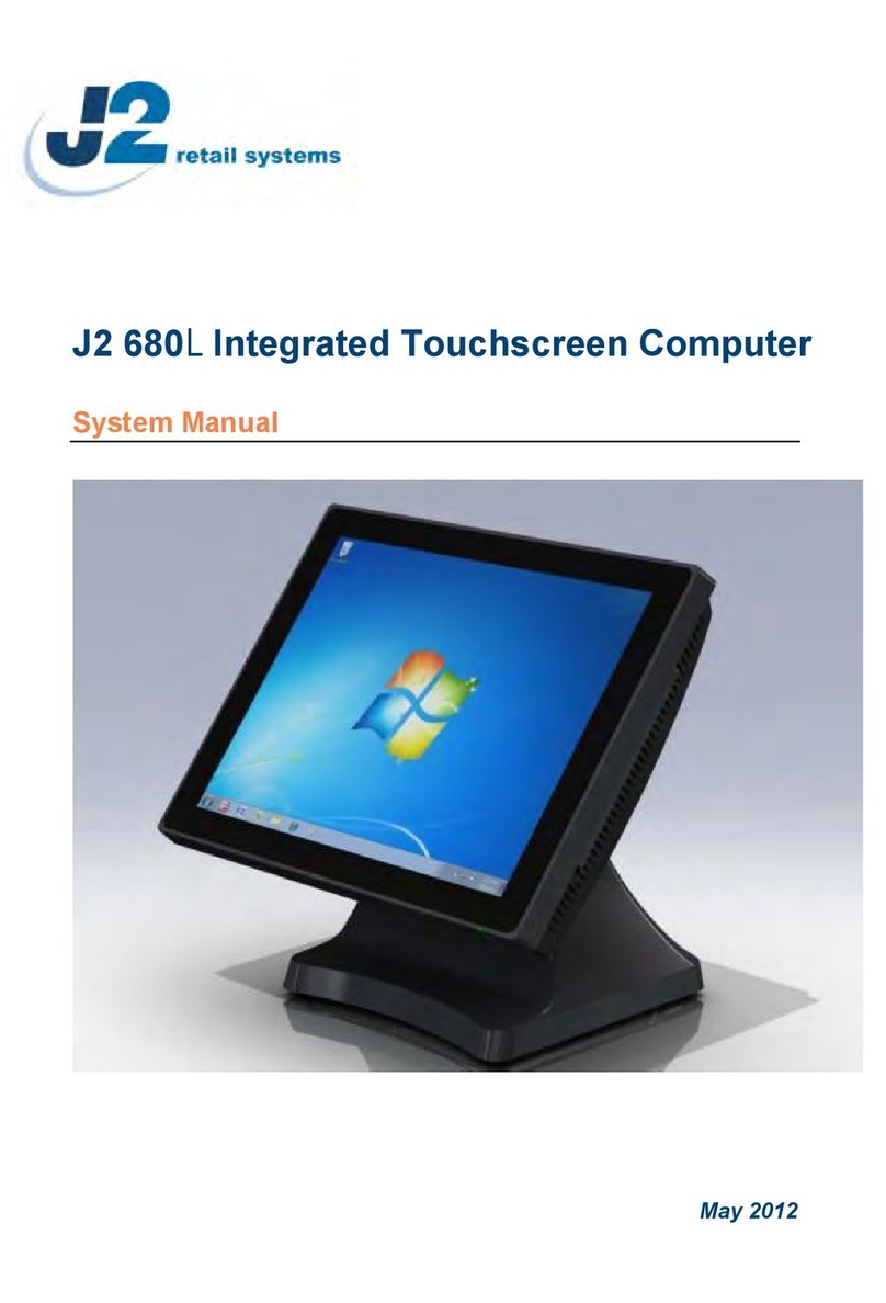
J2 225 User guide

J2 225 Integrated Touch Screen Computer
System Manual
April 2012

J2 225 System Manual
Version 1.0 May 29, 2012
2
Copyright © 2012 J2 Retail Systems Ltd
All rights reserved
Change history
Version 1.0 Release May 29, 2012

J2 225 System Manual
Version 1.0 May 29, 2012
3
Contents
Overview............................................................................................................................ 6
Design Concept J2 225...................................................................................................... 8
Specifications J2 225......................................................................................................... 9
J2 225 Integrated Touch Screen Computer.................................................................. 10
I/O Ports........................................................................................................................ 10
Off / On Button............................................................................................................. 10
Hard Disks .................................................................................................................... 11
Touch Screen ................................................................................................................ 11
System Board................................................................................................................ 12
J2 225 Display............................................................................................................... 12
Secondary Video Port ................................................................................................... 13
Serial ports .................................................................................................................... 14
USB Ports...................................................................................................................... 16
Ethernet Connection...................................................................................................... 16
Audio............................................................................................................................. 17
Cash Drawer Ports ........................................................................................................ 17
CMOS Clear.................................................................................................................. 19
Mini PCI-E.................................................................................................................... 19
Memory SODIMM(s)................................................................................................... 20
Power Supply................................................................................................................ 20
+12VDV Power Out ..................................................................................................... 21
Typical Power Consumption J2 225............................................................................. 21
Service.............................................................................................................................. 22
Swing Arm Base ........................................................................................................... 22
Removing the Power Supply ........................................................................................ 23
Cable Routing ............................................................................................................... 24
VESA Mounting ........................................................................................................... 26
J2 225 Disassembly Instructions................................................................................... 27
BIOS Setting.................................................................................................................... 33
Main Screen .................................................................................................................. 33
System Information....................................................................................................... 33
Advanced Screen .......................................................................................................... 34
Boot Configuration ....................................................................................................... 34
Power Configuration..................................................................................................... 35
COM Power and LCD Brightness Configuration......................................................... 35
Security Screen ............................................................................................................. 36
Boot Screen................................................................................................................... 36
Exit Screen.................................................................................................................... 37
Phoenix Secure Core Tiano BIOS ................................................................................ 37

J2 225 System Manual
Version 1.0 May 29, 2012
4
Device Drivers ................................................................................................................. 37
OPOS Drivers.................................................................................................................. 37
J2 225 Configuration Utility ..........................................................................................38
Installation..................................................................................................................... 38
Main.............................................................................................................................. 38
Power-On Hours ........................................................................................................... 39
Power Cycles ................................................................................................................ 39
Dim Timeout................................................................................................................. 39
Dim Brightness ............................................................................................................. 40
Basic MSR Settings ...................................................................................................... 41
Advanced MSR/iButton Settings.................................................................................. 42
Update MCU Firmware ................................................................................................ 44
MCU Option ................................................................................................................. 45
DimWake......................................................................................................................... 46
Installation..................................................................................................................... 46
J2 Health.......................................................................................................................... 47
Installation..................................................................................................................... 47
Tray Icon....................................................................................................................... 47
Logging to File.............................................................................................................. 48
Registry Entries............................................................................................................. 49
J2 Remote Monitoring Software................................................................................... 49
SMI BIOS Info Utility ....................................................................................................50
Installation..................................................................................................................... 50
Operations..................................................................................................................... 50
Cash Drawer Test Utility................................................................................................ 51
Installation..................................................................................................................... 51
Operation....................................................................................................................... 51
J2 Virtual Serial Ports Drivers...................................................................................... 53
J2 225 Options................................................................................................................. 54
J2 225 LCM 2x20 Character Customer Display.......................................................... 54
Installation..................................................................................................................... 55
J2 225 LCM Configuration Utility ............................................................................... 57
Installation..................................................................................................................... 57
J2 225 MSR...................................................................................................................... 60
Installation..................................................................................................................... 61

J2 225 System Manual
Version 1.0 May 29, 2012
5
J2 225 iButton Reader.................................................................................................... 63
Installation..................................................................................................................... 64
J2 225 Wall Mount / Counter-top Mount Kit ..............................................................66
Packing list.................................................................................................................... 66
Assembly....................................................................................................................... 67
J2 225 10.1 inch 1024 x 600 LCD Customer Display................................................... 71
Installation..................................................................................................................... 72
Contact Information....................................................................................................... 75
European Office............................................................................................................ 75
USA Office ................................................................................................................... 75
Australian Office........................................................................................................... 75
Website ......................................................................................................................... 75

J2 225 System Manual
Version 1.0 May 29, 2012
6
Overview
The J2 225 is a new generation of integrated touch screen Point of Sale computer,
brilliantly designed to be more compact and cost effective, yet rich in features and
versatility. The J2 225 moves away from the traditional POS 4:3 screen form factor and
uses the newer LED backlit 16:9 screen. This allows for a smaller overall physical
footprint yet allows for the display of more onscreen data. Retaining the core features and
capabilities of J2’s other tradition POS products, like the J2 615 and J2 630 units, the J2
225 takes advantage of the newer technologies currently available.
This integrated touch screen computer, like other J2 designs, features an “all-in-the-head”
design, and it also offers the versatility to be used as a counter top unit; or as a wall-
mount or pole-mounted terminal. The new smaller foot print and its unique swing arm,
die cast aluminum base allows for even more flexibility, leaving more counter space for
other uses. With an extremely wide range of adjustable heights and viewing angles, the
versatile J2 225 can be made to work in almost any POS environment. It weighs only
3.7kg and conveniently folds flat for shipping, therefore saving customers tremendously
on shipping and storing costs.
The J2 225 uses the latest Intel Atom dual core Cedarview processors, the 1.86GHz
D2550. Combining this with the Intel NM10 chipset provides excellent performance
capable of running most POS applications with a very low carbon foot print, all at a
competitive and attractive low price.
Even with its small foot print the J2 225 is incredibly feature rich. It comes standard with
2GB of memory, and offers a choice of either a 160GB hard drive or 16GB solid state
drive. Built standard with four serial ports, four USB ports, video output, audio in/out,
gigabit Ethernet, +12V output, as well as other built in peripherals (like MSR, customer
display and more) the J2 225 will perfectly satisfy most POS application requirements,
while looking sleek and elegant in any setting.
The J2 225 is available with your choice of either a zero bezel resistive touch screen or a
multi-touch projected capacitive touch screen. The new zero bezel five-wire resistive
touch screen provides the same quick response and feel of a resistive touch screen
traditionally used in the POS market. The new projective capacitive touch screen option
can be used in environments where multi-touch and gesturing are required, for example,
such as when using the new Windows 8 operating system.
The J2 225 is brilliantly designed to require little or no maintenance. The convection
cooled fan-less design means it can be used in very harsh environments. High dust,
grease or sea air will not affect its operation. High temperatures are also not a problem.
With a quick access HDD/SDD slot, a drive can be changed in just seconds if needed! A
snap-apart design allows the unit to be fully disassembled and assembled in just a few
minutes by just removing a few screws. Also available are optional Snap-on color kits, so
that the J2 225 can be customized to your customer needs.

J2 225 System Manual
Version 1.0 May 29, 2012
7
The J2 225 supports the standard Microsoft operating systems: Windows 7, POSReady 7,
Windows 7 Embedded, XP, POSReady 2009 and XP embedded, as well as the soon-to-
be-released Windows 8. The J2 225 is equally proficient with the many flavors of Linux.

J2 225 System Manual
Version 1.0 May 29, 2012
8
Design Concept J2 225
The J2 225, with its smooth modern appearance and capabilities, is perfectly suited for
most low cost commodity POS touch screen computer markets. The economical price and
outmatched performance will provide a great ROI for the end user, as they find it
extremely dependable as well as very easy to use. MSR and Secondary Display options
make it a perfect fit for companies in the POS markets, as well as for other industries,
including medical and healthcare applications, among many others.
To provide the highest performance at low cost with a long product life the J2 225 unit
design is based on the new Intel Atom Cedarview processor. This new 32nm part has
higher speed and runs on lower power than the current offering of Atom processors for
Intel.
The unit was built using as few screws as possible, providing ease of assembly and
disassembly, a major design achievement. This means that the touch screen, J2 225 panel,
or systems board can quickly be replaced in less than two minutes if needed (however
with the solid reliability of this creative unit, this should not even be necessary.)
A major goal in the enclosure design is to keep the total size of the unit as thin and as
small as possible. The thickness to the head is not much thicker that a standard notebook,
except for a slight bulge in the back where the electronics are located. The aluminum die
cast swing arm and fully adjustable base of the unit not only provide superb flexibility but
can also easily fold flat for shipping. The shipping box for the J2 225 is no bigger than
the size of an average notebook shipping box, which is also about 1/3 to 1/4 the size and
weight of other POS products.
As with all J2 products our ultimate goal is always reliability. Reliability is never
compromised because to reduce any cost at the expense of a dependable product would
be a false economy, and we firmly stand by our outstanding engineering and designs. We
always have our customer’s needs in mind as we move forward, offering the best in the
market today.

J2 225 System Manual
Version 1.0 May 29, 2012
9
Specifications J2 225
CPU and Chipset
Processor
Dual Core Intel Atom D2550 1.86GHz with 1MB Cache, 4 threads
with Integrated GMA 3650 Graphics controller
Chipset I/O
NM10
Memory
2 X DDR3 SO-DIMM, 4GB max, 2GB standard, 1067MHz
External Ports
Serial Ports
4 RS-232 RJ45 with power +12V BIOS controlled
USB Ports
4 USB 2.0
Ethernet
10/100/1000 MHz Ethernet port with status LEDs on connector
Cash Drawer Ports
1 RJ11 support 2 cash drawers +24V and +12V, Dual status lines
Secondary Video
Display Port with DVI, HDMI and VGA support
+12 Power
+12 Volt power out for secondary video display or other device
Audio
Combo Audio Jack for headset or headset with microphone
Internal I/O
Storage
One 3Gb/s SATA Port onboard, slide in/out 2.5“ HDD or SSD
J2 225 Display
14.0 inch 16:9 LVDS 1366x768 panel
LED backlight
LED backlight power with auto dimming control
Touch Screen
Resistive True Flat or Projective Capacitive with Multi-touch and gesturing
USB
4 onboard USB ports for optional devices, MSR, Wi-Fi, PCT
MSR
Onboard microcontroller of MSR on PS2
Serial
Serial port header for optional customer display or other option
Mini PCI-Express
Mini PCI Express slot for 802.11 b/g/n WiFi card and other functions
Optional Peripherals
MSR
Slim line MSR, Keyboard Wedge or virtual serial
iButton
iButton module, Keyboard Wedge or virtual serial
Fingerprint Reader
Digital Persona module, attached to front bottom of display head
Customer Display
J2 225 2x20 customer display, Serial
Secondary Video
10 inch 1024x600 16:9 J2 225 Secondary Display internal connection
Wireless
802.11 b/g/n Mini PCI Express card with internal antennaes
Environmental
Operating Temp.
0-40c
EMI
CE / FCC Class A
Safety
LVD external adaptor UL c/us, CE, TUV, others
Dust & Water
IP 64 front of unit, IP 54 whole unit
Power
100-240V 50-60Hz 19VDC 65 watts power supply
Weight
Head 2.5kg, Base 1.4kg, gross shipping weight 6kg
Dimensions
With base attached and folded: 360x260x80mm, 14.2”x10.2”x3.14”
System max height unfolded: 280mm, 11”

J2 225 System Manual
Version 1.0 May 29, 2012
10
J2 225 Integrated Touch Screen Computer
I/O Ports
Most I/O ports are accessible in the cable well at the bottom of the unit. Cables are routed
though the cable channel in the swing arm base. (See Cable Routing)
I/O Panel
Off / On Button
The Off /On button is located in the cable well, as shown below. This button is located
near the side to prevent accidental powering down by the user. The function of the button
can be controlled by the OS. If the J2 225 hangs for some reason it can always be
powered off by holding the Off /On button in for six seconds.
The J2 225 also supports the following: Restore on AC on power loss, Wake On LAN,
and Wake On RTC alarm features to control the system power up. The setting for these
features is controlled from the BIOS.
Off / On Button Location

J2 225 System Manual
Version 1.0 May 29, 2012
11
Hard Disks
One 2.5 inch SATA hard drive (HDD) or a solid state drive (SSD) are standard with the
J2 225. The SATA interface can support data transfer rates up to 3.0 GB/s. The J2 225
offers standard either a 160GB HDD or 16GB SSD, but can be ordered with other size
HDD or SSD as well. See J2 for details.
The HDD/SSD can be installed or removed in seconds by removing one screw. It is
easily accessed by removing the HDD cover retaining screw and sliding the drive out, the
HDD cover can then be unclipped from the drive.
HDD access panel
HDD slide in-slide out drive bay
Touch Screen
The J2 225 can be ordered with two different touch screen technologies, PCT or TFR.
The PCT unit uses a multi-touch Projected Capacitive Technology touch screen. The PCT
touch screen has no known failure mode-- it does not “wear out.” This screen is
tempered glass and does not reduce the brightness of the J2 225 panel. When operating
in a very high use environment, the PCT is the recommended touch screen technology.
The PCT touch screen will work with most gloves and stylus that are designed to work
with tablet computers, and the screen has a smooth glass surface that is reflective.
The TFR uses a five-wire true flat (zero bezel) resistive touch screen rated at 35 million
touches per point. The resistive technology is very responsive and is the traditional choice
for a hospitality POS system. The screen has an anti-reflective plastic film surface.
Both screens are fully spill proof, dust proof, and can be cleaned with a standard glass
cleaner. The J2 225 touch screen was designed to easily be changed, normally in less than
two minutes. Depending on operating environment and usage, both the Resistive and
PCT touch screens have strengths and weaknesses; therefore J2 offers both touch screen
technologies on the J2 225 unit, providing our customers with a choice for any
application requirement.

J2 225 System Manual
Version 1.0 May 29, 2012
12
System Board
POS computers typically have a lifespan of 10 years or longer, therefore product quality
is of the utmost importance. J2 225 electronics are built with high-end components to
ensure reliability and long lasting product performance.
The system board is designed for quick replacement, with just a few screws and cables to
unplug. The board can be swapped out in less than three minutes.
J2 225 System board
J2 225 Display
The J2 225 offers a 1366 x 768 resolution display with 16.2 Million colors, and a 14 inch
LED backlight with 16:9 aspect ratio screen. The brightness is rated at 220cd/m2. The
Intel controller allows for the display to be rotated to 0, 90, 180 or 270 degrees without
loss of performance. The driver can also scale the display resolution so that it can work
properly with applications written for 1024x768 or 800x600 resolutions.
The J2 225 electronics also supports dimming, and can be controlled directly by
Windows 7 or 8, or with J2 supplied utilities for Windows XP. Dimming levels between
5-100% are supported. A hardware auto dimming feature is built-in to ensure the longest
LED backlight life and to also provide the lowest power usage.

J2 225 System Manual
Version 1.0 May 29, 2012
13
Secondary Video Port
The J2 225 supports the newer digital video standard Display Port connector. This
connector supports a Display Port monitor, HDMI display, DVI or VGA monitor. When
used with HMDI or DVI displays, a passive adaptor cable must be used. When using a
VGA display, an active adaptor is to be used. With HDMI display Audio, support is
provided via the same HMDI cable.
The secondary video displays can be configured as Twin, Intel Dual Display Clone, or
Extended Desktop. Most all monitor resolutions from 640 x 480, up to 2560 x 1600 are
supported.
When the internal secondary J2 225 video display is used the secondary video port is not
available.
DisplayPort Video Port

J2 225 System Manual
Version 1.0 May 29, 2012
14
Serial ports
The J2 225 unit has four external RS232 serial ports, all of which can supply +12V
power. The serial ports use a ten pin RJ45 connector. The unit comes standard with four
serial cables, three 38cm (15”) RJ45 to DB9 adapter cables, and one 152cm (5’) RJ45 to
DB25 serial printer cable that works with EPSON and EPSON compatible printers.
All serial (COM) ports can be BIOS-enabled to provide +12Vpower to external devices.
This power is supplied via pin 10 of the RJ45 which corresponds to pin 9 on the DB9
adaptor. The maximum current per port is 1 amp, with a total maximum external loading
on the +12V of 3 amps.
A set of stick-on color coded labels are supplied with the cable adaptors, so that the
cables can be marked. This makes it easy to plug the cable back into the correct port,
should you need to service the unit.
Serial Ports
BIOS Setting Serial Port(s) Power Enable

J2 225 System Manual
Version 1.0 May 29, 2012
15
RJ45 to DB9 J2 Adaptor Cable Pin-Out when using CAT5/6 Cable
The J2 Cable Adaptor (supplied)
RJ45 to DB25 J2 Serial Pinter Cable Pin-out when using 8 wire CAT5/6 cable
Epson or Epson compatible serial printer cable
RJ45-10 Pin
DB9
Signal
RJ45- 8 Pin
DB9
Signal
Pin 1
---
---
---
---
---
Pin 2
Pin 1
DCD
Pin 1
Pin 1
DCD
Pin 3
Pin 6
DSR
Pin 2
Pin 6
DSR
Pin 4
Pin 2
RD
Pin 3
Pin 2
RD
Pin 5
Pin 7
RTS
Pin 4
Pin 7
RTS
Pin 6
Pin 3
SD
Pin 5
Pin 3
SD
Pin 7
Pin 8
CTS
Pin 6
Pin 8
CTS
Pin 8
Pin 4
DTR
Pin 7
Pin 4
DTR
Pin 9
Pin 5
GND
Pin 8
Pin 5
GND
Pin 10
Pin 9
RI
---
---
---
RJ45-10 Pin
Signal
DB25
Signal
RJ45- 8 Pin
Signal
DB25
Signal
Pin 1
---
---
---
---
---
---
---
Pin 2
DCD
---
---
Pin 1
DCD
---
---
Pin 3
DSR
Pin 20
DTR
Pin 2
DSR
Pin 20
DTR
Pin 4
RD
Pin 2
SD
Pin 3
RD
Pin 2
SD
Pin 5
RTS
Pin 5
CTS
Pin 4
RTS
Pin 5
CTS
Pin 6
SD
Pin 3
RD
Pin 5
SD
Pin 3
RD
Pin 7
CTS
Pin 4
RTS
Pin 6
CTS
Pin 4
RTS
Pin 8
DTR
Pin 6
DSR
Pin 7
DTR
Pin 6
DSR
Pin 9
GND
Pin 7
GND
Pin 8
GND
Pin 7
GND
Pin 10
---
---
---
---
---
---
---

J2 225 System Manual
Version 1.0 May 29, 2012
16
USB Ports
The J2 225 has 4 external and 4 internal USB 2.0 ports. The 4 external ports (see below)
are located in the cable well. The 4 internal ports are used for different functions, such as
using a PCT touch screen, RFID reader and/or other peripherals.
USB Ports
Ethernet Connection
The J2 225 uses the Realtek RTL8111 Gigabit Ethernet controller. The Ethernet
connector is located in the cable well, as shown below. The Ethernet controller supports
Wake on LAN, and the BIOS supports a PXE boot ROM as well. There is a LED on the
LAN connector, this Green LED light turns on when there is LAN activity.
Ethernet Connector

J2 225 System Manual
Version 1.0 May 29, 2012
17
Audio
The J2 225 uses the VIA1708B HD audio controller. There is one internal speaker.
A combo microphone jack and headset jack are located in the cable well of the J2 225, as
seen below, which allows for the connection of a microphone and headset, or audio out to
other devices.
Audio out is also supported on the DisplayPort when used with a HDMI monitor.
Audio Jack Location
Cash Drawer Ports
The J2 225 is equipped with one Cash Drawer port that can support one or two drawers.
This port is located in the cable well, and uses the industry standard RJ-11 connector and
pin-out (illustrated below).
Cash Drawer Ports

J2 225 System Manual
Version 1.0 May 29, 2012
18
6
1
Cash Drawer 1 Pin Assignment
Pin
Signal
1
GND
2
CD1 SOLENOID
3
STATUS / STATUS CD1
4
24V
5
CD2 SOLENOID
6
GND / STATUS CD2
The application may address the Cash Drawer port in two ways:
1) Using the J2-supplied OPOS drivers for Windows.
2) Direct access to the I/O ports
Cash Drawer Controller Register
The Cash Drawer Controller use one I/O address to control the Cash Drawer.
Register Location:
48Ch
Attribute:
Read / Write
Size:
8bit
BIT
BIT7
BIT6
BIT5
BIT4
BIT3
BIT2
BIT1
BIT0
Attribute
Read
Reserved
Write
Reserved
7
6
5
4
3
2
1
0
X
X
X
X
Reserved
Cash Drawer 1 fire
Cash Drawer 2 fire
Reserved
Cash Drawer 1 status
Cash Drawer 2 status
The “Y” cable used to support two cash drawers on the one RJ-11 is the same as is used
on Epson printers.

J2 225 System Manual
Version 1.0 May 29, 2012
19
CMOS Clear
The J2 225 CMOS can be cleared by unplugging the system board CMOS battery for 30
seconds before plugging it back in.
CMOS Battery
Mini PCI-E
The onboard Mini PCI Express connector is normally used for the optional internal
802.11b/g/n wireless LAN card.
Mounting Screw

J2 225 System Manual
Version 1.0 May 29, 2012
20
Memory SODIMM(s)
The J2 225 supports two SODIMM DDR3 memory sockets. The unit comes standard
with 2GB of main memory and can support up to a maximum of 4GB. The memory type
is DDR3 800/1066.
Power Supply
The J2 225 uses a notebook-type power supply that is mounted in the base of the unit.
The power supply is rated with an output of 65 watts 18.5 VDC 3.5 Amps, and has an
input rating of 100-240VAC at 50~60Hz 1.7Amps maximum. The power supply has an
efficiency rating V. The power supply connector is a standard notebook locking type that
plugs into the system power input connector, located in the cable well.
Power Input connector
Table of contents
Other J2 Touchscreen manuals