Federal APD PosiDRIVE User manual

PosiDRIVE Security Gate
Installation, Operation, and
Maintenance Manual


Safety Notice
People’s lives and property depend on your safe installation and maintenance of equipment. Listed below are
some important safety instructions and precautions which you should follow when working on any Federal
APD equipment. Failure to follow all safety precautions and instructions can result in serious injury or property
damage. Refer to the specific operational manual for a particular piece of equipment before beginning any
service work.
❑Frequently inspect the equipment to ensure that it is operating properly.
❑Ensure that maintenance is performed by the factory or an authorized distributor at least twice a year.
Safety Hints
❑Use vibrant colors on parking equipment at entrance lanes and exit lanes.
❑Always provide proper signage, both on the roadway and on other equipment.
❑Maintain the manufacturer’s warning stickers on gate arms and on other equipment.
❑Encourage the use of safety devices such as buzzers or flashing lights.
❑Always recommend that sidewalks be parallel to entrance lanes and exit lanes.
Safety Notice
To prevent injury to pedestrians, maintenance personnel, persons on bicycles or motorcycles, monitor all activity
in relation to entrance and exit lanes to ensure barrier gates are not accidentally lowered or raised. Take special
care when commanding any equipment action from a centralized computer system, especially when the control
equipment is not in your line of vision.
Use Pictograms
Federal APD, Inc. recommends using universally identifiable icons, or pictograms, in all entrance and exit lanes,
roadways, posts and walls. Paint “No Pedestrian” pictogram on the roadway adjacent to the parking barrier gate.
Pictograms depicting “No Motorcycles,” “No Wheelchairs,” “No Bicycles,” and “No Trucks” are also
recommended.
Safety Is Good Business
As an institution, municipality, or private operator, it is important to be aware of the potential liabilities which
may arise in normal parking operations. Adapting a “Safety First” attitude provides your business and your
patrons with a safer environment. After all, safety is good business!
To reduce the risk of severe personal injury or damage to equipment, turn off
the power to the equipment before performing any maintenance or repairs.
Failure to heed this warning could result in injury or even death of those who
come in contact with the product.
COPYRIGHT
PosiDRIVE Security Gate
Version 6
ZMA-330
© 2008-2009 Federal APD, Inc. All rights reserved. No part of this publication may be reproduced, transmit-
ted, transcribed, stored in a retrieval system, or translated into any language in any form by any means with-
out the written permission of Federal APD, Incorporated.
Printing Date
First Version ..............................................July 2000
Second Version..........................................December 2000
Third Version.............................................February 2001
Fourth Version...........................................July 2001
Fifth Version..............................................December 2003
Sixth Version .............................................June 2009

Warranty Information
Federal APD, Inc. warrants that the Products will be free from any defects in material and work-
manship under normal use and service, wear and tear excepted, for a period of two years from the
date of shipment from Federal APD. Exceptions to this warranty may include any products and/or
accessories that are used with Federal APD equipment but are not manufactured by Federal APD
Inc. In those instances where Federal APD is not the manufacturer of goods sold hereunder, Fed-
eral APD's warranty shall be the lesser of such manufacturers' warranty, or Federal APD's standard
warranty.
This warranty shall not apply to Products which have not been properly maintained or have been
subjected to misuse, neglect, accident or damage, or which have been modified, changed, or
reworked in any way, without prior written approval of Federal APD. Federal APD's sole obliga-
tion shall be to repair or replace, at Federal APD's option, any defective part or parts within such
two year period. Upon Federal APD's written instructions, allegedly defective goods shall be
returned to Federal APD for inspection. This warranty extends only to the original purchaser from
Distributor/Dealer and shall not cover repair, labor, or replacement of parts that are by nature
expendable. Distributor/Dealer agrees to deliver the Federal APD Limited Warranty then in effect
to each of its customers at the time of the sale. Distributor/Dealer shall have no authority to bind
Federal APD to any warranty beyond that extended therein. All Products are subject to design and/
or appearance modifications which are production standards at the time of shipment. Federal APD
may, but shall not be required to, modify or update Products shipped prior to a current production
standard.
THERE ARE NO OTHER WARRANTIES, EXPRESSED OR IMPLIED, INCLUDING BUT
NOT LIMITED TO ANY IMPLIED WARRANTIES OF MERCHANTABILITY OR FITNESS
FOR A PARTICULAR PURPOSE. IN NO EVENT SHALL FEDERAL APD BE LIABLE FOR
ANY LOSS OF PROFITS OR ANY INDIRECT OR CONSEQUENTIAL DAMAGES ARISING
OUT OF FEDERAL APD'S BREACH OF THIS WARRANTY OR ANY OTHER TERM OR
CONDITION OF THIS AGREEMENT.

PosiDRIVE Security Gate ZMA-330, Ver. 6 Table of Contents • i
Table of Contents
CHAPTER 1
Introduction .................................................................................................................................... 1
PosiDRIVE Security Gate Operational Overview ..................................................................... 2
Manual Operation................................................................................................................2
Automatic Operation ........................................................................................................... 2
Free Mode ..................................................................................................................... 3
Pay Mode ...................................................................................................................... 4
Pay/Free Mode .............................................................................................................. 5
Power Failure Detection ...................................................................................................... 6
PosiDRIVE Structural Overview............................................................................................... 6
Gate Enclosure (Cabinet) .................................................................................................... 6
Mechanical Components ..................................................................................................... 7
Drive Mechanism .............................................................................................................. 10
Electrical Components....................................................................................................... 10
Gate Arm ........................................................................................................................... 13
PosiDRIVE Controller....................................................................................................... 14
DIP Switches............................................................................................................... 15
Inputs........................................................................................................................... 15
Outputs........................................................................................................................ 16
Opening the Enclosure Door.................................................................................................... 16
Removing the Enclosure Cap................................................................................................... 16
CHAPTER 2
Installation..................................................................................................................................... 19
Installation Overview............................................................................................................... 20
Installing the Enclosure............................................................................................................ 20
Wiring the Gate........................................................................................................................ 23
Installing the Gate Arm............................................................................................................ 25
Install a Standard Gate Arm .............................................................................................. 26
Install a Folding Gate Arm ................................................................................................ 27
Change the Gate Arm Configuration................................................................................. 34
Setting the Mainsprings ........................................................................................................... 38
Disabling the Locked-Down Feature (Optional) ..................................................................... 40
Setting the DIP Switches.......................................................................................................... 42
CHAPTER 3
Maintenance and Repair.............................................................................................................. 45
Maintenance and Repair Overview.......................................................................................... 46
Performing Preventive Maintenance........................................................................................ 46
Grease Mainshaft Bearings................................................................................................ 47
Grease the Connection Rod Bearings................................................................................ 47
Troubleshooting a Problem...................................................................................................... 48
Locking, Unlocking, and Advancing the Gate Arm ................................................................ 49
Adding, Removing, or Replacing the Mainsprings.................................................................. 52
Aligning the Drive Mechanism................................................................................................ 54

ii • Table of Contents ZMA-330, Ver.6 PosiDRIVE Security Gate
APPENDIX A
Product Support............................................................................................................................57
Getting Help .............................................................................................................................58
Accessing the Distributor Resource Center..............................................................................59
APPENDIX B
Order and Repair Procedures .....................................................................................................61
Placing an Order.......................................................................................................................62
Requesting a Repair..................................................................................................................62
Locate a Part Number ........................................................................................................63
Mainsprings.................................................................................................................64
Enclosure.....................................................................................................................65
Electrical Components ................................................................................................68
Standard Gate Arm......................................................................................................70
Folding Gate Arm........................................................................................................73
Drive Mechanism ........................................................................................................78
Index ..............................................................................................................................................83

PosiDRIVE Security Gate ZMA-330, Ver. 6 List of Figures • iii
List of Figures
Figure 1.1 Free Gate with Opening Loop...................................................................................... 3
Figure 1.2 Pay Gate ....................................................................................................................... 4
Figure 1.3 Pay/Free Gate ............................................................................................................... 5
Figure 1.4 Enclosure Components................................................................................................. 7
Figure 1.5 Mechanical Components .............................................................................................. 8
Figure 1.6 Electrical Components ............................................................................................... 11
Figure 1.7 Standard Gate Arm..................................................................................................... 13
Figure 1.8 Folding Gate Arm....................................................................................................... 14
Figure 1.9 PosiDRIVE Controller ............................................................................................... 14
Figure 1.10 Draw Latch............................................................................................................... 17
Figure 2.1 PosiDRIVE Security Gate Footprint Dimensions...................................................... 21
Figure 2.2 Gate Cabinet Warning Label (Part # 20-3469) .......................................................... 22
Figure 2.3 Wiring with the Federal APD Detector Harness........................................................ 24
Figure 2.4 Wiring with a Non-Federal APD Detector Harness................................................... 25
Figure 2.5 Standard Gate Arm Installation.................................................................................. 26
Figure 2.6 Gate Arm Warning Label (Part # 20-4343) ............................................................... 27
Figure 2.7 Dimensions for Folding Gate Arm Mounting Hole ................................................... 28
Figure 2.8 Installing the Cable Tower ......................................................................................... 29
Figure 2.9 Attaching the Fixed Section of the Folding Gate Arm to the Gate Flange ................ 30
Figure 2.10 Attaching the Folding Section to the Gate Arm Stabilizer....................................... 31
Figure 2.11 Attaching the Stabilized Folding Section to the Gate Arm Fixed Secton................ 32
Figure 2.12 Attaching the Cable Turnbuckle to the Gate Arm.................................................... 33
Figure 2.13 Gate Arm Configuration Components ..................................................................... 34
Figure 2.14 Pivot Bar................................................................................................................... 35
Figure 2.15 Set Screws ................................................................................................................ 36
Figure 2.16 Mainshaft Removal .................................................................................................. 36
Figure 2.17 Spring Adjustment Bolts .......................................................................................... 39
Figure 2.18 Down Bump Stop ..................................................................................................... 41
Figure 2.19 DIP switches in the Open Position........................................................................... 42
Figure 3.1 Motor Crank Position when the Gate Arm is Down .................................................. 51
Figure 3.2 Motor Crank Position when the Gate Arm is Up ....................................................... 51
Figure 3.3 Mainspring Connection Bar ....................................................................................... 53
Figure 3.4 Mainspring Attachment Points................................................................................... 53
Figure 3.5 Drive Mechanism Alignment ..................................................................................... 55
Figure B.1 Mainspring Parts........................................................................................................ 64

iv • List of Figures ZMA-330, Ver.6 PosiDRIVE Security Gate
Figure B.2 Enclosure Cap Parts ................................................................................................... 65
Figure B.3 Enclosure Door Parts ................................................................................................. 66
Figure B.4 Enclosure Cabinet Parts ............................................................................................. 67
Figure B.5 Electrical Sub-Panel Parts.......................................................................................... 68
Figure B.6 Detector Bracket and Backup Battery Assembly Parts.............................................. 70
Figure B.7 Standard Gate Arm Parts ........................................................................................... 71
Figure B.8 Folding Gate Arm and Stabilizer Parts ...................................................................... 73
Figure B.9 Folding Gate Arm Cable Tower Parts ....................................................................... 75
Figure B.10 Folding Gate Arm Adapter and Fixed Section Parts ............................................... 76
Figure B.11 Folding Gate Arm Packages .................................................................................... 77
Figure B.12 Drive Mechanism Installation Parts......................................................................... 78
Figure B.13 Drive Mechanism Frame Parts (View 1) ................................................................. 79
Figure B.14 Drive Mechanism Parts (View 2) ............................................................................ 80

PosiDRIVE Security Gate ZMA-330, Ver. 6 Introduction • 1
CHAPTER 1
Introduction
This chapter contains the following topics:
PosiDRIVE Security Gate Operational Overview ..............................................2
Manual Operation .........................................................................................2
Automatic Operation.....................................................................................2
Free Mode ..............................................................................................3
Pay Mode................................................................................................4
Pay/Free Mode .......................................................................................5
Power Failure Detection ...............................................................................6
PosiDRIVE Structural Overview ........................................................................6
Gate Enclosure (Cabinet)..............................................................................6
Mechanical Components...............................................................................7
Drive Mechanism........................................................................................10
Electrical Components................................................................................10
Gate Arm.....................................................................................................13
PosiDRIVE Controller................................................................................14
DIP Switches........................................................................................15
Inputs....................................................................................................15
Outputs .................................................................................................16
Opening the Enclosure Door .............................................................................16
Removing the Enclosure Cap ............................................................................16

2 • PosiDRIVE Security Gate Operational Overview ZMA-330, Ver.6 PosiDRIVE Security Gate
PosiDRIVE Security Gate Operational Overview
The PosiDRIVE Security Gate is a low-maintenance security gate, with a
microprocessor-based controller that protects roadways up to 20 feet (6 m). The
PosiDRIVE gate has a variable operating time, from 1.5 to 6 seconds, depending on the
length of the gate arm. The gate is capable of operating in an ambient temperature of
-30°F (-34°C) to 140°F (60°C) without any adjustments. It can be configured as a right-
hand or left-hand flange gate without any additional hardware.
The PosiDRIVE Security Gate works with several types of vend devices, such as vehicle
detection loops, card reading devices, or ticket issuing devices. The gate controller
inputs support both manual and automatic operation.
Manual Operation
For manual operation a toggle switch is wired into the Raise/Lower input on the gate
controller (Figure 2.3, on page 24). When the toggle switch is placed in the “raise”
position (i.e., the circuit is completed), the gate arm raises and remains in the up position
until the toggle switch is moved to the “lower” position.
Automatic Operation
For automatic operation, one or more vend devices are wired into the Vend input on the
gate controller (Figure 2.3, on page 24). Depending on the vend device(s), the lane runs
in one of the following modes:
■“Free Mode” on page 3
■“Pay Mode” on page 4
■“Pay/Free Mode” on page 5
For all automatic operation modes, a vehicle detection loop that resides under the gate
arm (loop B) is wired into the B Presence input on the gate controller. The gate
automatically lowers when the patron pulls off of the loop B.
PosiDRIVE Security Gate ZMA-330, Ver. 6 PosiDRIVE Security Gate Operational Overview • 3
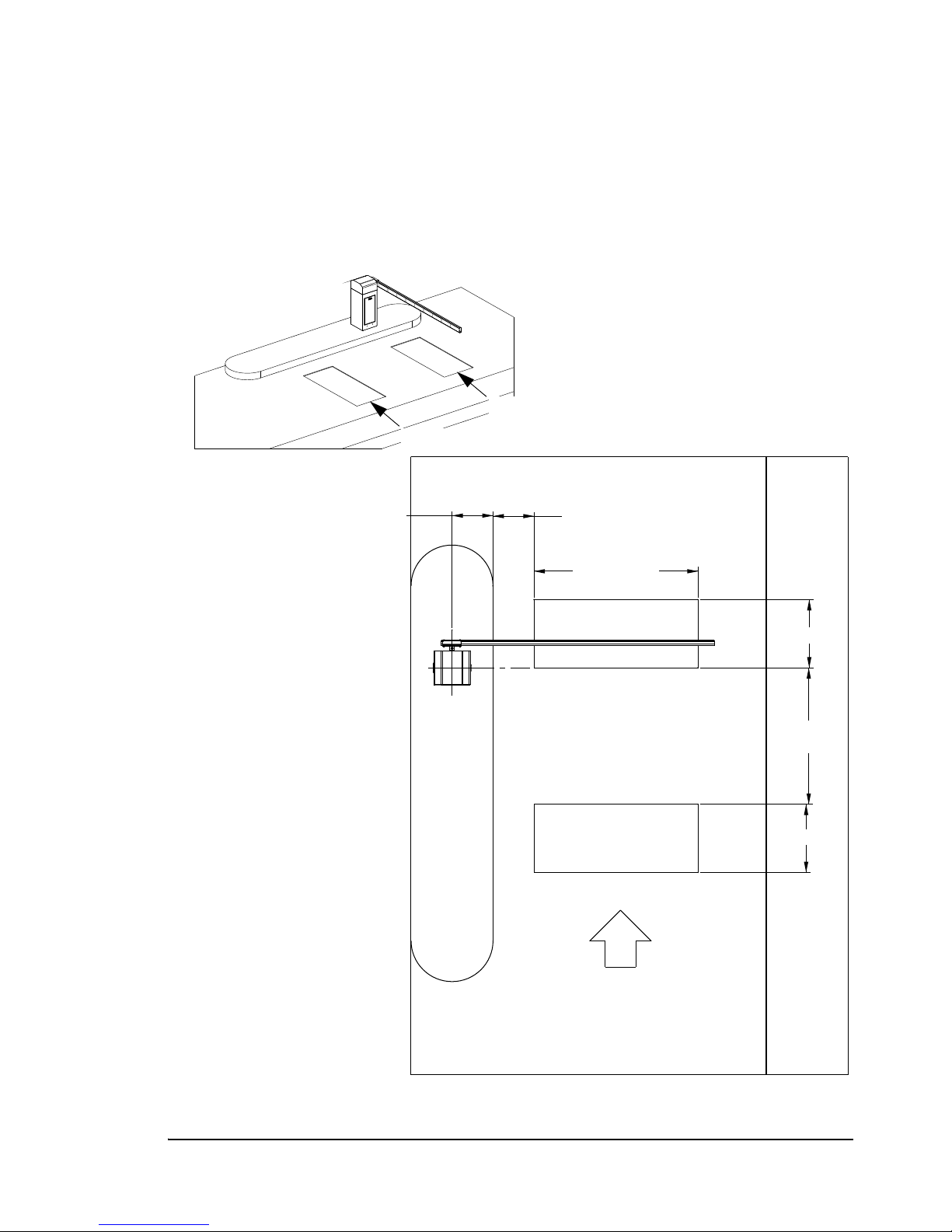
Free Mode
Free mode is used in a single-direction lane through which a patron enters or exits the
facility free of charge. This mode requires two vehicle detector loop inputs: loop A and
loop B. When a vehicle pulls onto the loop A, the gate arm raises. The gate arm lowers
after the vehicle clears loop B.
Figure 1.1 Free Gate with Opening Loop
TRAFFIC FLOW
2'-6" (.76 m)
5' (1.5 m)
MAX.
2'-6" (.76 m)
1'-6" (.46 m)
6' (1.8 m)
1'-6" (.46 m)
A
B
Loop A
Loop B

4 • PosiDRIVE Security Gate Operational Overview ZMA-330, Ver.6 PosiDRIVE Security Gate
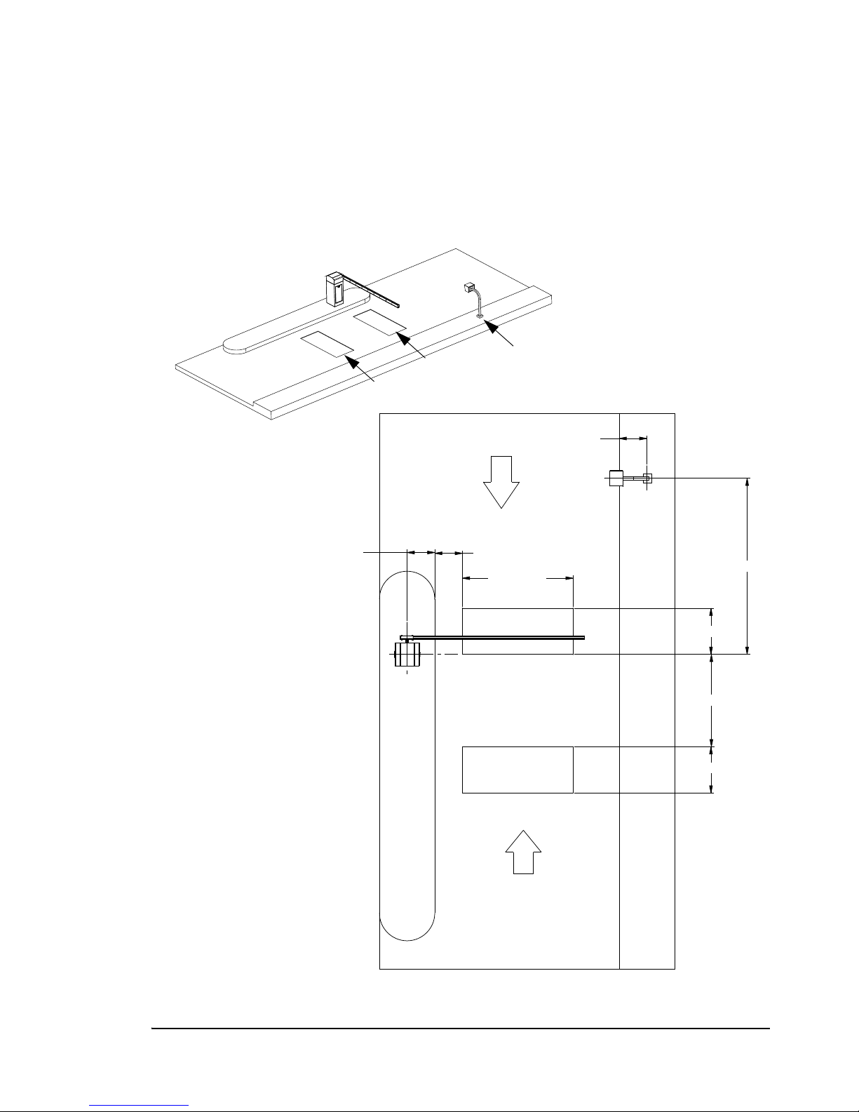
Pay Mode
Pay mode is used in a single-direction lane in which controlled access is required to
enter or exit the facility. This mode requires a vehicle detection loop (loop B) and a
vend-device such as a card reader or a switch that a booth attendant uses to raise the
gate. The gate arm lowers after the vehicle clears loop B.
Note: An additional loop (loop A) may be used to enable the vend device, for
example, the lane may contain a ticket issuing device that is activated when the
patron pulls onto loop A.
Figure 1.2 Pay Gate
TRAFFIC FLOW
2'-6" (.76 m)
8'-3" (2.5 m)
2'-6" (7.6 m)
1'-6" (.46 m)
6' (1.8 m)
9'-6" (2.9 m)
1'-6" (.46 m)
A
B
Loop B
Loop A (optional)
Vend Device
PosiDRIVE Security Gate ZMA-330, Ver. 6 PosiDRIVE Security Gate Operational Overview • 5
Pay/Free Mode
Pay/free mode is used in a dual-direction lane. It requires two vehicle detection loops
(loop A and loop B) and a vend-device such as a card reader. In the free direction,
vehicle presence on loop A vends the gate. In the pay direction, the vend-device vends
the gate. In either direction, the gate arm lowers after the vehicle clears the loop B.
Figure 1.3 Pay/Free Gate
TRAFFIC FLOW INTRAFFIC FLOW IN
TRAFFIC FLOW OUTTRAFFIC FLOW OUT
2'-6"2'-6" (.76 m)(.76 m)
5'5' (1.5 m)(1.5 m)
2'-6"2'-6" (.76 m)(.76 m)
1'-6"1'-6" (.46 m)(.46 m)
6'6' (1.8 m)(1.8 m) 9'-6" (2.9 m)9'-6" (2.9 m)
1'-6"1'-6" (.46 m)(.46 m)
1'-6"1'-6" (.46 m)(.46 m)
A
B
Loop A
Loop B Vend Device

6 • PosiDRIVE Structural Overview ZMA-330, Ver.6 PosiDRIVE Security Gate
Power Failure Detection
The PosiDRIVE controller is able to sense when there is a power failure. If the
controller is programmed to raise the gate arm during a power failure, the controller uses
the power from backup battery assembly to raise the gate arm automatically. The gate
arm stays in the up position until the power is restored.
Note: If the controller is not programmed to automatically raise the gate, the gate must
be raised manually. See “Locking, Unlocking, and Advancing the Gate Arm” on
page 49.
PosiDRIVE Structural Overview
This section describes the following PosiDRIVE components:
■“Gate Enclosure (Cabinet)” on page 6
■“Mechanical Components” on page 7
■“Drive Mechanism” on page 10
■“Electrical Components” on page 10
■“Gate Arm” on page 13
■“PosiDRIVE Controller” on page 14
Gate Enclosure (Cabinet)
Federal APD, Inc. builds the PosiDRIVE gate enclosure using 0.090 inch galvanized
steel. The enclosure is weather resistant and allows proper operation in all weather
conditions and temperatures ranging from -30°F (-34°C) to 140°F (60°C). Louvres on
the back and cutouts on the four bottom corners of the enclosure provide air circulation,
thus preventing excessive moisture buildup.
The enclosure is 15 inches W x 16 inches D x 42 inches H (38 cm W x 41 cm D x 107
cm H), finished in yellow or white powder coat paint. The enclosure consists of two
pieces, a base and a removable cap. The base houses the power supply and electronics
package as well as provides the main structure of the enclosure. In addition, the base
provides reinforced flanges for installation, hookup points for the mainsprings, and
mounting provisions for the drive mechanism. Figure 1.4 illustrates the main
components of the gate enclosure.
The enclosure cap is a removable piece that provides easy access to the drive
mechanism without disrupting the operation of the gate. Inspection and maintenance can
be performed easily by removing the enclosure cap. It is secured by four draw latches to
the base, requiring no tools to remove or install. See “Removing the Enclosure Cap” on
page 16.

PosiDRIVE Security Gate ZMA-330, Ver. 6 PosiDRIVE Structural Overview • 7
Figure 1.4 Enclosure Components
Mechanical Components
The PosiDRIVE gate is powered by a 150 watt, 24 VDC brushless DC gear motor.
The motor is connected directly to a fully sinusoidal four-bar drive mechanism. A
sinusoidal mechanism has the distinct advantage of providing smooth, progressive
acceleration and a mechanical advantage at the limits of travel, where it is needed most.
This arrangement eliminates the need for Vee-belts and their associated maintenance.
One advantage of a brushless DC motor is that the gate can adjust the speed of the entire
system depending on the size of the arm installed. Therefore, the same motor and
gearbox can be used in all situations, allowing the flexibility of using any size gate arm.
Another advantage to the brushless DC motor is the ability of the gate to know where
the gate arm is at all times. The motor provides an output that is monitored by the
controller. The controller interprets the signals to determine arm position and speed.
Using this information, the PosiDRIVE gate operates like a full servo system, providing
benefits such as not requiring mechanical contact to limit its travel, no limit switches,
and an extremely sensitive collision detect system.
The PosiDRIVE gate uses as many as four internal extension mainsprings to
counterbalance the weight of the gate arm. The number of mainsprings and their
adjustment must be properly set at the time of installation in order for the gate to
function properly. When correctly set, these mainsprings offset the torque on the
mechanism created by the weight of the arm, providing a safe, balanced system which
greatly reduces the power required by the motor and increases the efficiency of the gate.
Figure 1.5, on page 8 shows the PosiDRIVE mechanical components. Component
descriptions follow the illustration.
Enclosure Cap
Enclosure Base
Enclosure Door
Gate Arm
8 • PosiDRIVE Structural Overview ZMA-330, Ver.6 PosiDRIVE Security Gate
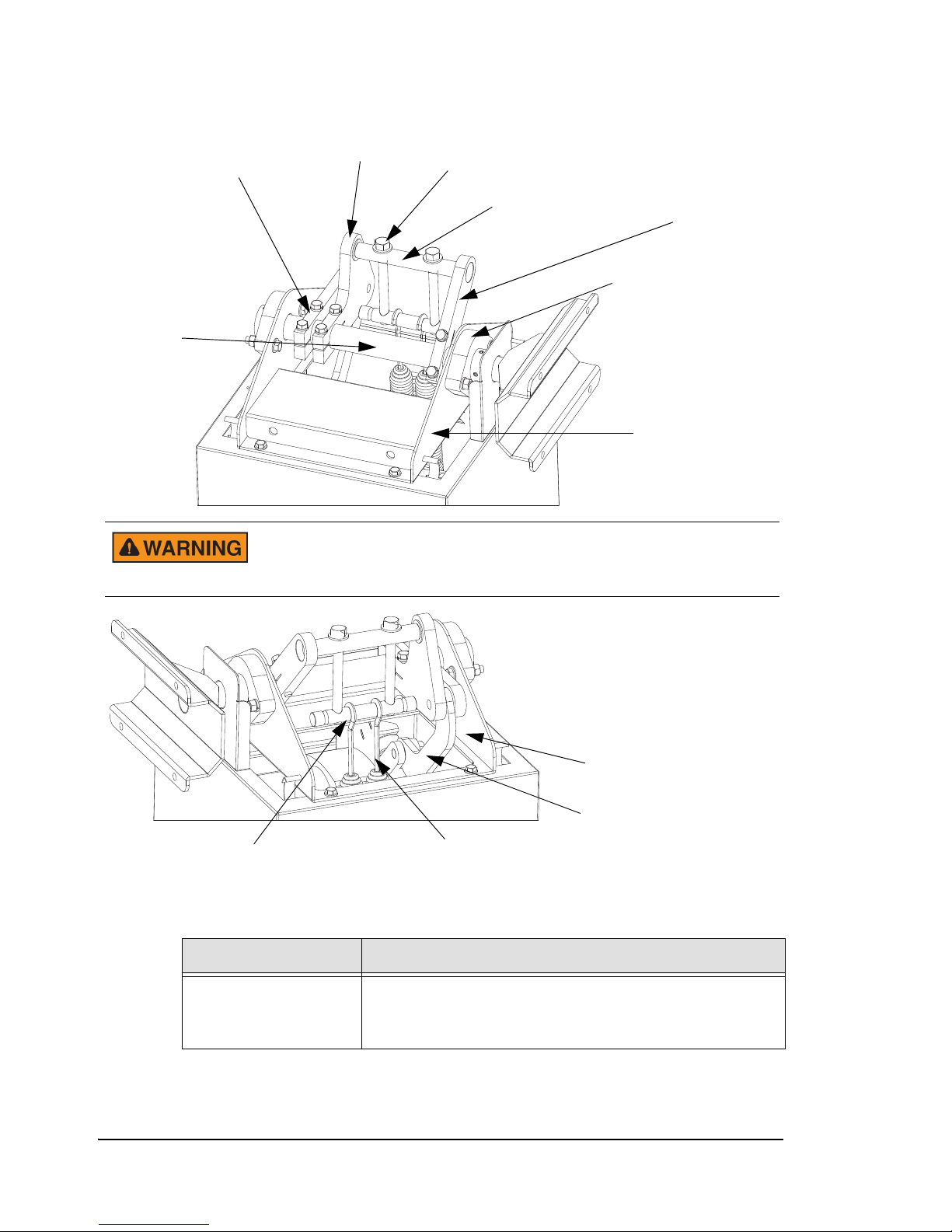
Figure 1.5 Mechanical Components
Table 1.1 Mechanical Component Descriptions
Component Description
Mechanism Frame Steel frame that forms the foundation for the PosiDRIVE
mechanism. All of the drive components, including the
motor and mainshaft are attached to the mechanism frame.
Mainshaft Crank
Part 1
Mainspring Adjustment Bolt
Mainspring Pivot Bar Mainspring Crank
Mainshaft Bearing
Mainshaft
Mechanism Frame
Mainshaft Crank
Part 2
Connecting Rod
Motor Crank
Mainspring
Mainspring Connection Bar
To prevent a serious pinching injury including dismemberment, use
care when working with the drive mechanism and alway terminate
power prior to performing maintenance or repairs.

PosiDRIVE Security Gate ZMA-330, Ver. 6 PosiDRIVE Structural Overview • 9
Motor 24 VDC gear motor that powers the PosiDRIVE gate. The
motor and gear box are contained in a single sealed
housing for simplicity and maintenance-free operation.
Motor Crank Link that is attached to the output shaft of the motor. This
link is attached to the motor shaft by means of a friction
clamp but also includes a keyed shaft to prevent slipping
under all conditions.
Connecting Rod Intermediate link in the PosiDRIVE system. The connecting
rod incorporates two high quality spherical bearings for
maximum life and excellent tolerance to misalignment.
Mainshaft Crank Part 1 One of two combined pieces that attach to the mainshaft
and provide the driving force to the mainshaft.
Mainshaft Crank Part 2 The second of the main driving links. This piece is also
designed to serve as an attachment point for the spring
system. It incorporates a single high quality deep groove
ball bearing that one end of the mainspring pivot bar rests
in.
Mainspring Crank Other link attached to the mainshaft that serves as the
second attachment point for the spring system.
Mainspring Pivot Bar Bar that rides in the pair of ball bearings in the mainshaft. It
links and supports the mainspring adjustment bolts.
Mainspring
Connection Bar
Bar to which the mainsprings are attached. The connection
bar incorporates four shallow grooves to keep the
mainsprings properly positioned.
Mainspring
Adjustment Bolts
The two long bolts that connect the mainspring connection
bar to the mainspring pivot bar. They provide the means to
fine-tune the spring tension to a given arm.
Mainshaft Shaft that carries the gate arm at one end and to which the
driving links are attached.
Mainshaft Bearings Large bearings mounted to the sides of the mechanism
frame that carry the mainshaft.
Gate Arm Flange Arm carrier that is attached to the end of the mainshaft.
Table 1.1 Mechanical Component Descriptions (Continued)
Component Description

10 • PosiDRIVE Structural Overview ZMA-330, Ver.6 PosiDRIVE Security Gate
Drive Mechanism
The drive mechanism in the PosiDRIVE gate is a direct drive, sinusoidal mechanism.
This system provides a substantial mechanical advantage for the motor at the beginning
and ending of a cycle when it is most needed. The result of this is that when the gate is at
the extreme limits of travel, in the “full down” or “full up” position, the mechanism is
“locked” and cannot be manually advanced by pushing the gate arm. In other words, at
the full up and full down positions, the mechanism cannot be driven or advanced by any
torque applied to the mainshaft. When servicing the PosiDRIVE gate, you must be
aware of this.
There are times, such as when setting the mainsprings, when you must operate the
mechanism by hand, using the gate arm. It is also necessary at times during this
procedure and others to ensure that the linkage is in the fully locked up position for
safety. Raising the gate arm by hand will NOT bring the linkage into this position. It will
bring it closed, but it will not be fully locked.
In order to lock the mechanism, you must always advance the mechanism by hand for
the last few degrees of travel. That is, if you raise or lower the arm by hand to what feels
like the limits of its travel, the mechanism still must be manually advanced a small
amount to ensure that it is in the locked position. If the mechanism is already locked,
either up or down, then it becomes impossible to get it out of this position by moving the
gate arm. The mechanism must be manually advanced out of the locked position before
moving the gate arm. This is a side effect of the sinusoidal linkage and the variable
mechanical advantage the system provides.
For instructions on manually advancing the mechanism into and out of the locked
positions, see “Locking, Unlocking, and Advancing the Gate Arm” on page 49.
Electrical Components
The use of a 24 VDC motor in the PosiDRIVE gate provides several electrical benefits.
First, by using a low (non-hazardous) voltage throughout the system, the risk of shock to
service personnel is greatly reduced. The PosiDRIVE gate utilizes a universal input 24
volt power supply. This supply can accept input voltages anywhere from 85 VAC to 264
VAC at 50 or 60 Hz. This allows the PosiDRIVE gate to be installed into virtually any
voltage environment without modification, providing maximum flexibility. The
nameplate rating for power consumption is 2 amps for 115 VAC and 1 amp for 220
VA C .
The PosiDRIVE gate is also equipped with a backup battery assembly, which provides
power to the controller and motor in the event of a power failure to allow the
PosiDRIVE gate to raise the arm. It is not intended to operate the gate in a power failure
mode, but just to provide the option of raising the gate to allow patrons to exit. It also
does not power any loop circuits. Automatically raising the gate during a power failure
is a configurable option. See “Setting the DIP Switches” on page 42.

PosiDRIVE Security Gate ZMA-330, Ver. 6 PosiDRIVE Structural Overview • 11
The PosiDRIVE gate can detect a line power failure and will wait (operating on battery
power) for a period of 10 seconds before raising the arm. This eliminates false responses
to transient (short term) power glitches. On detection of the return of line power, again a
delay of 10 seconds is provided before normal operation is resumed. The backup battery
assembly has ample power to provide this feature for several years before replacement.
Figure 1.6, on page 11 shows the PosiDRIVE gate electrical components. Component
descriptions follow the illustration.
Figure 1.6 Electrical Components
The door safety switch disconnects power to the motor under ALL
circumstances. If the door safety switch is bypassed (not normally
recommended) and the circuit breaker switch is turned off for any
reason, after 10 seconds, the gate activates under battery power and
raises the arm. The powerful drive mechanism can cause serious
bodily injury. Do not bypass the door safety switch unless absolutely
necessary.
Table 1.2 PosiDRIVE Electrical Component Descriptions
Component Description
Junction Box A junction is located on the electrical sub-panel below the
circuit breaker, where an installer can mount a convenience
outlet.
Safety Switch
PosiDRIVE Controller
Power Supply
Motor Driver
Board Manual/Auto Switch
Circuit Breaker/Master
Power Switch
Junction Box
Electical Subpanel

12 • PosiDRIVE Structural Overview ZMA-330, Ver.6 PosiDRIVE Security Gate
Circuit Breaker Switch This is the main overload protection mechanism for the
entire gate. It is also the master power switch. CAUTION:
The door safety switch disconnects power to the motor
under ALL circumstances. If the door safety switch is
bypassed (not normally recommended) and the breaker
switch is turned off for any reason, the system will respond
to this as a line power failure. After 10 seconds, the gate will
activate under battery power and raise the arm. Use
extreme caution when servicing the gate and be aware of
this condition. This is why the door safety switch should not
be bypassed unless absolutely necessary.
Electrical Sub-Panel Steel panel mounted inside the enclosure, which holds all of
the electrical components.
PosiDRIVE Controller “Brain” behind the PosiDRIVE gate and its operation. It is a
plug-in, microprocessor-based controller that monitors and
directs all operations of the gate. It is capable of operating
on input voltages ranging from 18 VDC to 32 VDC.
Motor Driver Board “Brain” behind the brushless DC motor. It controls the
proper operation of the motor as well as regulates the power
delivered to the motor.
Safety Switch A plunger-style switch that automatically terminates power
to the motor when the enclosure door is open. To bypass
the switch, pull out the plunger. To reactivate the switch,
depress the plunger. The plunger springs back to the safe
position.
Manual/Auto Switch Setting the switch to the Manual position raises the arm to
the up position indefinitely. Setting the switch to the
Automatic position causes the gate to resume normal
operation.
Table 1.2 PosiDRIVE Electrical Component Descriptions (Continued)
Component Description
To avoid serious injury, use
extreme caution when
bypassing the safety switch.
Make sure all technicians are
clear of the drive mechanism
and the gate arm path before
bypassing the switch.
Table of contents
Popular Gate Opener manuals by other brands

AGS
AGS 104 installation guide

Genius
Genius FALCON 14 MC Instructions for use

SEA
SEA ALPHA 200 STANDARD installation manual

Nice
Nice hyke HK7224 Instructions and warnings for installation and use

LIFE home integration
LIFE home integration ERGO ER4 Instructions for installation, use and maintenance

RIB
RIB SUPER 3600 L1 CRX Installation


cedamatic
cedamatic GLISS 1300 Operating instructions and spare parts catalogue

Erreka
Erreka JEDI JES100E manual

CAME
CAME FROG A installation manual

Chamberlain
Chamberlain SLY500E-120 manual

Comunello Automation
Comunello Automation SWIFT Installation and user manual

RIB
RIB IDRO 27 Operating and installation instructions