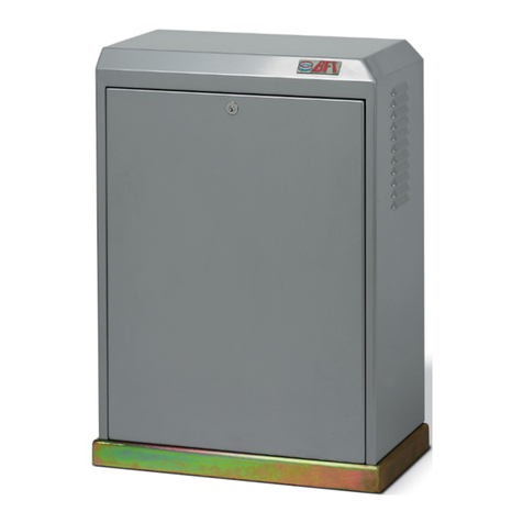
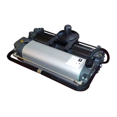
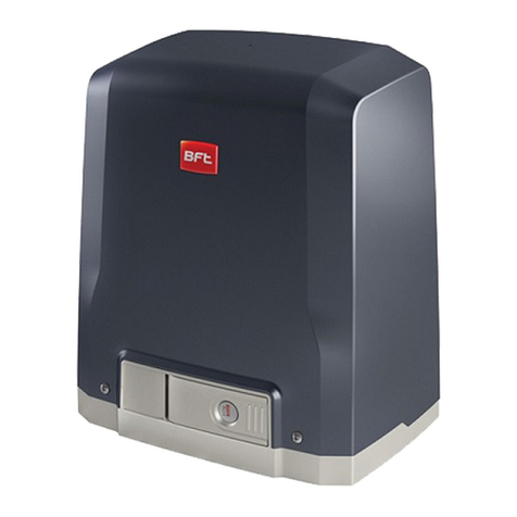
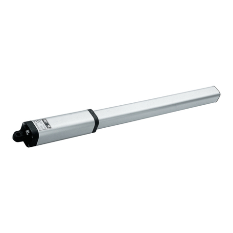
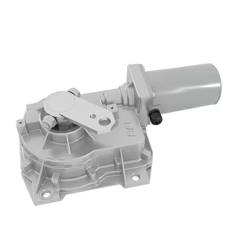
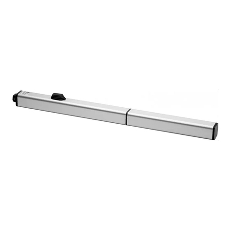
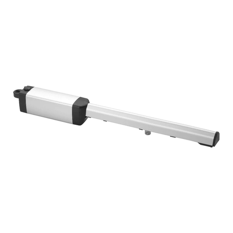
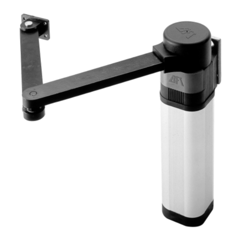
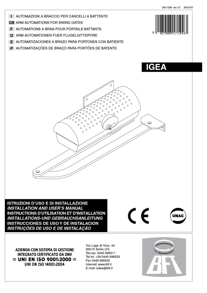
BFT DEIMOS BT User manual

ISTRUZIONI D'USO E DI INSTALLAZIONE
INSTALLATION AND USER'S MANUAL
INSTRUCTIONS D'UTILISATION ET D'INSTALLATION
INSTALLATIONS-UND GEBRAUCHSANLEITUNG
INSTRUCCIONES DE USO Y DE INSTALACION
INSTRUÇÕES DE USO E DE INSTALAÇÃO
D811314 ver. 04 09-07-03
I
GB
F
D
E
P
DEIMOS BT
Via Lago di Vico, 44
36015 Schio (VI)
Tel.naz. 0445 696511
Tel.int. +39 0445 696533
Fax 0445 696522
Internet: www.bft.it
E-mail: [email protected]
ATTUATORE IN BASSA TENSIONE PER CANCELLI SCORREVOLI A CREMAGLIERA
LOW-VOLTAGE ACTUATOR FOR RACK SLIDING GATES
ACTIONNEUR A BASSE TENSION POUR PORTAILS COULISSANTS A CREMAILLERE
NIEDERSPANNUNGSANTRIEB FÜR ZAHNSTANGEN-SCHIEBETORE
SERVOMOTOR DE BAJA TENSION PARA CANCELAS CORREDERAS DE CREMALLERA
ACCIONADOR DE BAIXA TENSÄO PARA PORTÖES DE CORRER A CREMALLERA
8 027908 183613

2 -
DEIMOS BT Ver. 04
D811314_04

DEIMOS BT Ver. 04
- 3
D811314_04
MANUALE D’USO ITALIANO
NelringraziarViperlapreferenzaaccordataaquestoprodotto,ladittaècertache
da esso otterrete le prestazioni necessarie al Vostro uso. Leggete attentamente
l’opuscolo “Avvertenze” ed il “Libretto istruzioni” che accompagnano questo
prodotto in quanto forniscono importanti indicazioni riguardanti la sicurezza,
l’installazione, l’uso e la manutenzione. Questo prodotto risponde alle norme
riconosciute della tecnica e della disposizioni relative alla sicurezza. Confermia-
mo che è conforme alle seguenti direttive europee: 89/336/CEE, 73/23/CEE (e
loro modifiche successive).
1) GENERALITÀ
L’attuatore DEIMOS BT offre un’ampia versatilità d’installazione, grazie alla
posizione estremamente bassa del pignone, alla compattezza dell’attuatore
e alla regolazione dell’altezza e profondità di cui dispone. Il limitatore di
coppia elettronico, regolabile, garantisce la sicurezza contro lo
schiacciamento. La manovra manuale d’emergenza si effettua con estrema
facilità tramite una manopola. L’arresto a fine corsa è controllato da
microinterruttori elettromeccanici. La centralina di comando è incorporata.
Sono disponibili i seguenti accessori opzionali:
- Kit batteria tampone mod. SBBAT
Incorporabile nell’attuatore, consente il funzionamento dell’automazione
anche se manca per un breve periodo l’alimentazione di rete.
- Manopola di sblocco mod. MSC (fig.2)
Manopola di sblocco fissa con chiave personalizzata.
2) SICUREZZA
L’automazione, se installata ed utilizzata correttamente, soddisfa il grado di
sicurezza richiesto. Tuttavia è opportuno osservare alcune regole di comporta-
mento per evitare inconvenienti accidentali.
Prima di usare l’automazione, leggere attentamente le istruzioni d’uso e conser-
varle per consultazioni future.
• Tenere bambini, persone e cose fuori dal raggio d’azione dell’automazione, in
particolare durante il funzionamento.
• Nonlasciareradiocomandioaltridispositividicomandoallaportatadeibambini
onde evitare azionamenti involontari dell’automazione.
• Non contrastare volontariamente il movimento dell’anta.
• Nontentarediapriremanualmenteilcancellosenonèstatosbloccatol’attuatore
con l’apposita manopola di sblocco.
• Non modificare i componenti dell’automazione.
• In caso di malfunzionamento, togliere l’alimentazione, attivare lo sblocco di
emergenza per consentire l’accesso e richiedere l’intervento di un tecnico
qualificato (installatore).
• Per ogni operazione di pulizia esterna, togliere l’alimentazione di rete, e se
presente almeno un polo delle batterie.
• Tenerepuliteleottichedellefotocelluleedidispositividisegnalazioneluminosa.
Controllarecheramiedarbustinondisturbinoidispositividisicurezza(fotocellule).
• Per qualsiasi intervento diretto all’automazione, avvalersi di personale qualifi-
cato (installatore).
• Annualmente far controllare l’automazione da personale qualificato.
3) SBLOCCO MANUALE
Lo sblocco manuale o di emergenza va attivato quando si deve aprire manual-
menteilcancelloo in ogni caso di non funzionamento o funzionamento anomalo
dell’automazione. Per eseguire la manovra di emergenza, bisogna:
• Inserire la chiave standard nell’apposita sede (fig.1) e ruotarla in senso anti-
orario (90°), quindi ruotare la manopola di sblocco in senso orario per tutta la
sua corsa. In questo modo si rende folle il pignone permettendo così,
l’apertura manuale del cancello.
Attenzione: Non spingere violentemente l’anta del cancello, ma accom-
pagnarla per tutta la sua corsa.
• Per ripristinare il comando motorizzato, ruotare la manopola in senso
antiorario per tutta la sua corsa e quindi ruotare in senso orario la chiave
standard fino alla ritenuta. Riporre la chiave in un luogo sicuro e conosciuto
agli interessati
Nel caso sia applicata la manopola di sblocco con chiave personalizzata (fig.2),
agire come segue:
• Inserire la chiave personalizzata nella serratura, ruotare la chiave in senso
antiorario per 90°.
• Impugnare la manopola di sblocco e ruotarla in senso orario (fig.2) fino al suo
arresto. In questo modo si rende folle il pignone permettendo così, l’apertura
manuale del cancello.
• Spingere manualmente l’anta del cancello accompagnandola per tutta la sua
corsa.
La chiave non si può togliere dalla serratura fino a quando la manopola non
viene riportata nella posizione iniziale (azionamento motorizzato).
• Per ripristinare il comando motorizzato, ruotare la manopola in senso
antiorario per tutta la sua corsa, riportare la chiave in posizione di chiusura
quindi togliere la chiave e riporla in un luogo sicuro e conosciuto agli
interessati.
4) MANUTENZIONE E DEMOLIZIONE
La manutenzione dell’impianto va fatta eseguire regolarmente da parte di
personale qualificato. I materiali costituenti l’apparecchiatura e il suo imballo
vanno smaltiti secondo le norme vigenti.
AVVERTENZE
Il buon funzionamento dell’operatore è garantito solo se vengono rispet-
tate i dati riportati in questo manuale. La ditta non risponde dei danni
causati dall’inosservanza delle norme di installazione e delle indicazioni
riportate in questo manuale.
Le descrizioni e le illustrazioni del presente manuale non sono impegna-
tive. Lasciando inalterate le caratteristiche essenziali del prodotto, la Ditta
siriservadiapportare in qualunque momento lemodifichecheessa ritiene
convenienti per migliorare tecnicamente, costruttivamente e commercial-
mente il prodotto, senza impegnarsi ad aggiornare la presente pubblica-
zione.
Fig. 1
OPEN
CLOSE
Fig. 2
1
2
OPEN
CLOSE
CLOSE
1
2
OPEN
CLOSE
MSC

4 -
DEIMOS BT Ver. 04
D811314_04
USER’S MANUAL
ENGLISH
Thank you for buying this product, our company is sure that you will be
more than satisfied with the product’s performance. The product is supplied
with a “Warnings” leaflet and an “Instruction booklet”. These should both
be read carefully as they provide important information about safety,
installation, operation and maintenance. This product complies with the
recognised technical standards and safety regulations. We declare that
this product is in conformity with the following European Directives: 89/336/
EEC and 73/23/EEC (and subsequent amendments).
1) GENERAL OUTLINE
The DEIMOS BT actuator offers ample installation versatility thanks to its
compactness, the extremely low position of its pinion as well as the height
and depth adjustments available. The adjustable electronic torque limiter
ensures antisquash safety. The emergency manual manoeuvre can be
activated very easily by means of a knob. The end-of-run stop is controlled
by electromechanical limit microswitches. The control unit is incorporated.
The following optional accessories are available:
- SBBAT mod. Buffer battery kit
It can be incorporated into the actuator, and allows the automation system to
operate even when the mains power supply is disconnected for a short time.
- MSC mod. Release knob (fig.2)
Fixed release knob with personalised key.
2) SAFETY
If correctly installed and used, this automation device satisfies the required
safety level standards. However, it is advisable to observe some practical
rules in order to avoid accidental problems.
Beforeusing the automation device, carefully read the operation instructions
and keep them for future reference.
• Keep children, persons and things outside the automation working area,
particularly during operation.
• Keep radio control or other control devices out of children’s reach, in
order to avoid any unintentional automation activation.
• Do not intentionally oppose the leaf movement.
• Do not attempt to open the gate by hand, if the actuator has not been
released by means of the appropriate release knob.
• Do not modify the automation components.
• In case of malfunction, disconnect the power supply, activate the
emergency release to gain access to the actuator and request the
assistance of a qualified technician (installer).
• Before proceeding to any external cleaning operation, disconnect the
mains powers supply and at least one of the battery pole, if fitted.
• Keep the photocell optical components and luminous signal indication
devicesclean.Checkthat thesafetydevices (photocells) are notobscured
by branches or shrubs.
• For any direct assistance to the automation system, request the
assistance of a qualified technician (installer).
• Have qualified personnel check the automation system once a year.
3) MANUAL RELEASE
The manual or emergency release is to be activated when a gate must be
opened by hand, and in all cases where the automation system fails to
operate or operates incorrectly. To carry out the emergency manoeuvre,
proceed as follows:
• Insert the standard key into its appropriate seat (fig. 1) and rotate it
anticlockwise (90°), then rotate the release knob clockwise along its
entire stroke.This way the pinion is made to idle, and therefore allows
the gate to be opened by hand.
Warning: Do not push the gate leaf hard,but rather help it along its
entire stroke.
• To reset motor-driven control, rotate the knob anticlockwise along its
entire stroke, and then rotate the standard key clockwise until it is held
tight. Keep the key in a safe place which is known to all the people
concerned.
In the case where the release knob is supplied with a personalised key
(fig.2), proceed as follows:
• Insert the personalised key into the lock, rotate the key anticlockwise by
90°.
• Hold the release knob and rotate it clockwise (fig. 2) until it stops. This
way the pinion is made to idle, and therefore allows the gate to be
opened by hand.
• Push the gate leaf by hand, helping it along its entire stroke.
The key cannot be taken out of the lock until the knob is brought back
to its initial position (motor-driven activation).
• To reset motor-driven control, rotate the knob anticlockwise along its
entire stroke, move the key back to its locking position;then take the key
out and keep it in a safe place which is known to all the people concerned.
4) MAINTENANCE AND DEMOLITION
The maintenance of the system should only be carried out by qualified
personnel regularly.The materials making up the set and its packing must
be disposed of according to the regulations in force.
WARNINGS
Correct controller operation is only ensured when the data contained
in the present manual are observed. The company is not to be held
responsible for any damage resulting from failure to observe the
installation standards and the instructions contained in the present
manual.
The descriptions and illustrations contained in the present manual
arenot binding. The Companyreserves the rightto make any alterations
deemed appropriate for the technical, manufacturing and commercial
improvement of the product, while leaving the essential product
features unchanged, at any time and without undertaking to update
the present publication.
Fig. 1
OPEN
CLOSE
Fig. 2
1
2
OPEN
CLOSE
1
2
OPEN
CLOSE
MSC

DEIMOS BT Ver. 04
- 5
D811314_04
MANUEL D’UTILISATION FRANÇAIS
Nousvousremercionspouravoirchoisiceproduit.Noussommescertains qu’il
vous offrira les performances que vous souhaitez. Lisez attentivement la
brochure “Avertissements” et le “Manuel d’instructions” qui accompagnent
ce produit, puisqu’ils fournissent d’importantes indications concernant la
sécurité, l’installation, l’utilisation et l’entretien. Ce produit est conforme aux
règles reconnues de la technique et aux dispositions de sécurité. Nous
certifions sa conformité avec les directives européennes suivantes: 89/336/
CEE, 73/23/CEE (et modifications successives).
1) GÉNÉRALITÉS
L’actionneur DEIMOS BT offre de grandes possibilités d’installation, grâce à
la position très basse du pignon, à la compacité de l’actionneur et au réglage
de la hauteur et de la profondeur dont il dispose. Le limiteur de couple
électronique, réglable, assure la sécurité contre l’écrasement. La manoeuvre
manuelle d’urgence se fait avec une facilité extrême à travers une poignée.
L’arrêt à la fin de course est contrôlé par des microinterrupteurs
électromécaniques. L’unité de commande est incorporée.
Les accessoires en option suivants sont disponibles:
- Kit batterie de secours mod. SBBAT
Elle peut être incorporée dans l’actionneur et elle permet le fonctionnement de
la motorisation même en cas de faute d’électricité pour une brève période.
- Poignée de déblocage mod. MSC (fig.2)
Poignée de déblocage fixe avec clé personnalisée.
2) SECURITE
La motorisation, si installée et utilisée correctement, est conforme au degré de
sécurité demandé. Il est toutefois conseillé de respecter ces quelques règles
de conduite afin d’éviter tout inconvénient ou accident. Avant d’utiliser la
motorisation, lire attentivement les instructions d’utilisation et les conserver en
cas de besoin.
• Tenir les enfants, les personnes et les choses hors du rayon d’action de la
motorisation, particulièrement pendant le fonctionnement.
• Ne pas laisser les radio commandes ou d’autres dispositifs de commande
à la portée des enfants, afin d’éviter des actionnements involontaires de la
motorisation.
• Ne pas contraster volontairement le mouvement du portail.
• Ne pas chercher à ouvrir manuellement le portail si l’actionneur n’a pas été
débloqué avec la poignée de déblocage spéciale.
• Ne pas modifier les composants de la motorisation.
• En cas de mauvais fonctionnement, couper l’alimentation, activer le
déblocage d’urgence afin de permettre l’accès et demander l’intervention
d’un technicien qualifié (installateur).
• Pour toute opération de nettoyage extérieur, couper l’alimentation de ligne
et, si présent, au moins un pôle des batteries.
• Nettoyer les optiques des cellules photoélectriques et les dispositifs de
signalisation lumineuse. S’assurer que des branches ou des arbustes ne
dérangent pas les dispositifs de sécurité (cellules photoélectriques).
• Pour toute interventiondirectesurlamotorisation,s’adresseràdupersonnel
qualifié (installateur).
• Chaque année, faire contrôler la motorisation par du personnel qualifié.
3) DEBL0CAGE MANUEL
Ledéblocage manueloud’urgencedoitêtreactivésiondoitouvrirmanuellement
leportailou dans touslescasdemauvaisfonctionnementou de fonctionnement
anormal de la motorisation. Pour effectuer la manoeuvre d’urgence, il faut:
• Insérer la clé standard dans son logement (fig. 1) et la tourner dans le sens
contraire à celui des aiguilles d’une montre (90°), puis tourner la poignée
de déblocage dans le sens des aiguilles d’une montre pour toute sa course.
De cette façon le pignon devient fou, ce qui permet l’ouverture manuelle du
portail.
Attention: Ne pas pousser violemment le vantail du portail, mais
l’accompagner pour toute sa course.
• Pour rétablir la commande motorisée, tourner la poignée dans le sens
contraire à celui des aiguilles d’une montre pour toute sa course, puis
tourner la clé standard dans le sens des aiguilles d’une montre jusqu’à
l’arrêt.Rangerlaclédansunlieusûr et connuparlespersonnesconcernées.
Si la poignée de déblocage avec clé personnalisée est appliquée (fig. 2), agir
comme suit:
• Insérer la clé personnalisée dans la serrure, tourner la clé dans le sens
contraire à celui des aiguilles d’une montre pour 90°.
• Tourner la poignée de déblocage dans le sens des aiguilles d’une montre
(fig.2) jusqu’à son arrêt.De cette façon le pignon devient fou, ce qui permet
l’ouverture manuelle du portail.
• Pousser manuellement le vantail du portail en l’accompagnant pour toute
sa course.
La clé ne peut pas être enlevée de la serrure tant que la poignée n’est pas
reportée dans sa position initiale (actionnement motorisé).
• Pour rétablir la commande motorisée, tourner la poignée dans le sens
contraire à celui des aiguilles d’une montre pour toute sa course, reporter
la clé en position de fermeture, puis enlever la clé et la ranger dans un lieu
sûr et connu par les personnes concernées.
4) ENTRETIEN ET DEMOLITION
L’entretien de l’installation doit être effectué régulièrement de la part de
personnel qualifié. Les matériaux constituant l’appareillage et son emballage
doivent être mis au rebut conformément aux normes en vigueur. Les piles
constituent des déchets spéciaux.
AVERTISSEMENTS
Le bon fonctionnement de l’actionneur n’est assuré que si les données
fourniesdanscemanuelsontrespectées.Le constructeur ne répond pas
pour les dommages provoqués par le non respect des normes
d’installation et des indications fournies dans ce manuel.
Les descriptions et les figures de ce manuel n’engagent pas le
constructeur. En laissant inaltérées les caractéristiques essentielles du
produit,la Société se réserve le droit d’apporterà n’importe quel moment
les modifications qu’elle juge opportunes pour améliorer le produit du
point de vue technique, commercial et de construction, sans s’engager
à mettre à jour cette publication.
Fig. 1
OPEN
CLOSE
Fig. 2
1
2
OPEN
CLOSE
1
2
OPEN
CLOSE
MSC

6 -
DEIMOS BT Ver. 04
D811314_04
BEDIENUNGSANLEITUNG
DEUTSCH
Wir danken Ihnen, daß Sie sich für diese Anlage entschieden haben. Ganz
sicher wird sie mit ihren Leistungen Ihren Ansprüchen vollauf gerecht
werden. Lesen Sie aufmerksam die Broschüre “Hinweisen“ und die
“Gebrauchsanweisung“ durch, die dem Produkt beiliegen. Sie enthalten
wichtige Hinweise zur Sicherheit, Installation, Bedienung und Wartung der
Anlage. Dieses Produkt genügt den anerkannten technischen Regeln und
Sicherheitsbestimmungen. Wir bestätigen, daß es mit folgenden
Europäischen Richtlinien übereinstimmt: 89/336/EWG, 73/23/EWG (und
ihren nachfolgende Änderungen) .
1) ALLGEMEINES
Der Antrieb DEIMOS BT ist wegen der sehr niedrigen Ritzelposition, seiner
Kompaktheit und wegen der verstellbaren Höhe und Tiefe extrem vielseitig
installierbar. Die elektronische, regelbare Krafteinstellung bildet den
Quetschschutz der Anlage. Im Notfall kann sie kinderleicht mit einem
Handgriff bedient werden. Der Endschalterbetrieb erfolgt durch
elektromechanische Mikroschalter. Die Steuerung ist bereits integriert.
Auf Wunsch sind folgende Zubehörteile erhältlich:
- Bausatz Pufferbatterie Modell SBBAT
In den Antrieb einbaufähig gestattet sie den Betrieb der Automatikanlage
selbst bei kurzzeitigem Stromausfall.
- Entriegelungshandgriff Modell MSC (Fig.2)
Fester Entriegelungshandgriff mit individuellem Schlüssel.
2) SICHERHEIT
Die Anlage erfüllt bei richtiger Installation und Bedienung die erforderlichen
Sicherheitsstandards.Trotzdem ist es sinnvoll, einige Verhaltensmaßregeln
zu beachten, um unvorhergesehene Zwischenfälle auszuschließen .
Vor Gebrauch der Anlage die Betriebsanleitung aufmerksam lesen und für
zukünftige Einsichtnahme aufbewahren .
• Kinder, Erwachsene und Sachwerte sollten sich außerhalb des Wirk-
radius der Anlage befinden, besonders während des Betriebes .
• KeineFernbedienungenoder andereSteuerungsvorrichtungen inReich-weite
von Kindern liegen lassen. Sie könnten die Anlage ungewollt in Gang setzen.
• Der Flügelbewegung nicht willentlich Kraft entgegensetzen .
• Nicht versuchen, das Tor von Hand zu öffnen, wenn nicht vorher der
Antrieb mit dementsprechenden Entriegelungshandgriff entsperrt wurde.
• Keine Umbauten an Anlagenkomponenten vornehmen .
• Bei Betriebsstörungen die Stromversorgung unterbrechen, durch Betä-
tigung der Notentriegelung den Zugang ermöglichen und einen fach-
kundigen Techniker (Installateur) hinzuziehen .
• Vor jeder Außenreinigung die Stromversorgung unterbrechen und - falls
vorhanden - zumindest einen Batteriepol abklemmen .
• Halten Sie die Linsen der Lichtschranken und die Blinkleuchte sauber.
Prüfen Sie, ob Äste oder Gesträuch die Sicherheitsvorrichtun-gen
beeinträchtigen können (Lichtschranke) .
• Wenn eine Arbeit unmittelbar an der Anlage erforderlich ist, wenden Sie
sich hierzu an fachkundiges Personal (Installateur) .
• Die Anlage muß einmal jährlich von Fachpersonal kontrolliert werden .
3) ENTSPERRUNG VON HAND
Die Hand- oder Notfallentsperrung ist zu betätigen, wenn das Tor manuell
geöffnet werden muß, also in allen Fällen, in denen die Anlage nicht mehr oder
nur gestört funktioniert. Die Notfallbedienung läuft folgendermaßen ab:
• Den Standardschlüssel einstecken (Fig. 1) und gegen den Uhrzeigersinn
(um90°)drehen, anschließend den Entsperrungsgriff im Uhrzeigersinnganz
umdrehen. Dadurch wird der Ritzel freigegeben und das Tor läßt sich von
Hand öffnen.
Vorsicht: Der Torflügel darf nicht mit Gewalt angeschoben werden,
begleiten Sie ihn jedoch mit der Hand auf seinem Weg.
• Um den Motorbetrieb wieder aufzunehmen, drehen Sie den Griff gegen den
Uhrzeigersinnganzum,danndenStandardschlüsselimUhrzeigersinndrehen,
bis er zurückgehalten wird.Bewahren Sie ihn an einem sicheren Ort auf, der
allen Benutzern bekannt ist.
Wird der Entsperrungsgriff mit personalisiertem Schlüssel betätigt (Fig. 2),
gehen Sie folgendermaßen vor:
• Den personalisierten Schlüssel ins Schloß stecken und um 90°gegen den
Uhrzeigersinn drehen.
• Entsperrungshandgriff im Uhrzeigersinn drehen, bis es nicht mehr geht (Fig.
2). Dadurch wird der Ritzel freigelegt und das Tor läßt sich von Hand öffnen.
• Durch Anschieben begleiten Sie den Flügel auf seinem gesamten Weg mit
der Hand.
DerSchlüsselläßtsicherstwiederausdemSchloßziehen,wennderHandgriff
in die Anfangsposition (Motorbetrieb) zurückgebracht wird.
• Um den Motorbetrieb wieder aufzunehmen, drehen Sie den Handgriff gegen
den Uhrzeigersinn ganz um, dann den Schlüssel in die Verschlußposition
zurückführen, abziehen und an einem sicheren, allen Beteiligten bekannten
Ort aufbewahren.
4) INSTANDHALTUNG UND VERSCHROTTUNG
Die Anlagenwartung ist regelmäßig von Fachleuten vorzunehmen. Die
Materialien, aus denen die Apparatur besteht und ihre Verpackung sind
vorschriftsmäßig zu entsorgen. Die Batterien dürfen nicht in die Umwelt
gelangen.
HINWEISE
Der einwandfreie Betrieb des Antriebes ist nur dann garantiert, wenn die
Angaben aus diesem Handbuch beachtet werden. Der Hersteller haftet
nicht für Schäden, die durch Mißachtung der Installationsanweisungen
und der Angaben aus diesem Handbuch entstehen.
Die Beschreibungen und bildlichen Darstellungen in diesem Handbuch
sind unverbindlich. Der Hersteller behält sich - ohne auch zur
Aktualisierung dieser Unterlagen verpflichtet zu sein - jederzeit vor,
Änderungen vornehmen, wenn er diese für technische oder bauliche
Verbesserungen als notwendig erachtet und die wesentlichen
Produkteigenschaften unverändert bleiben.
Fig. 1
OPEN
CLOSE
Fig. 2
1
2
OPEN
CLOSE
1
2
OPEN
CLOSE
MSC

DEIMOS BT Ver. 04
- 7
D811314_04
MANUAL DE USO ESPAÑOL
Al agradecerle la preferencia que ha manifestado por este producto, la
empresa está segura de que de él obtendrá las prestaciones necesarias
para sus exigencias. Lea atentamente el folleto “Advertencias” y el
“Manual de instrucciones” que acompañan a este producto, pues
proporcionan importantes indicaciones referentes a la seguridad, la
instalación, el uso y el mantenimiento del mismo.
Esteproducto cumple los requisitosestablecidos por lasnormas reconocidas
de la técnica y las disposiciones relativas a la seguridad. Confirmamos su
conformidad con las siguientes directivas europeas: 89/336/CEE, 73/23/
CEE (y modificaciones sucesivas).
1) GENERALIDADES
El servomotor DEIMOS BT ofrece una amplia versatilidad de instalación,
gracias a la posición extremadamente baja del piñón, a la solidez del
servomotor y a la regulación de la altura y la profundidad de que dispone.
El limitador de par electrónico, regulable, garantiza la seguridad contra el
aplastamiento. La maniobra manual de emergencia se efectúa con extre-
ma facilidad mediante una manecilla. La parada al final de la carrera es
controlada por unos microinterruptores electromecánicos.
La central de mando está incorporada.
Están a disposición los siguientes accesorios opcionales:
- Kit de baterías tampón mod. SBBAT
Incorporable en el servomotor, permite el funcionamiento del automatismo
incluso si falta, por un breve período de tiempo, el suministro de corriente.
- Manecilla de desbloqueo mod. MSC (fig.2)
Manecilla de desbloqueo fija con llave personalizada.
2) SEGURIDAD
El automatismo, si se instala y utiliza correctamente, satisface el grado de
seguridad requerido. Sin embargo, es conveniente observar algunas
reglas de comportamiento para evitar inconvenientes accidentales. Antes
de usar el automatismo, lea atentamente las instrucciones de uso y
consérvelas para consultas futuras.
• Mantener a niños, personas y cosas fuera del campo de acción del au-
tomatismo, especialmente durante su funcionamiento.
• No dejar radiomandos u otros dispositivos de mando al alcance de los
niños, para evitar el accionamiento involuntario del automatismo.
• No contrastar voluntariamente el movimiento de la hoja.
• No intentar abrir manualmente la cancela si antes no se ha desbloqueado
el servomotor con la manecilla de desbloqueo.
• No modificar los componentes del automatismo.
• En caso de mal funcionamiento, cortar el suministro de corriente, activar
el mecanismo de desbloqueo de emergencia para consentir el acceso y
solicitar la intervención de un técnico cualificado (instalador).
• Antes de realizar cualquier operación de limpieza externa, cortar el
suministro de corriente y, si está presente el kit de baterías tampón,
desconectar al menos un polo de las baterías.
• Mantener limpias las lentes de las fotocélulas y los dispositivos de
señalización luminosa.Controlar que ramas o arbustos no interfieran con
los dispositivos de seguridad (fotocélulas).
• Si resulta necesario efectuar una intervención directa en el automatismo,
llamar a personal cualificado (instalador).
• Una vez al año, es preciso hacer controlar el automatismo por personal
cualificado.
3) DESBLOQUEO MANUAL
El desbloqueo manual o de emergencia se activa cuando hay que abrir
manualmentela cancela y cada vez que no funciona o que el funcionamiento
no es correcto. Para cumplir la maniobra de emergencia hay que:
• Insertarlallaveestándarensualojamiento(fig.1)y girarla hacia la izquierda
(90°), luego girar la manecilla de desbloqueo hacia la derecha hasta que
haga tope. Así se libera el piñón, pudiendo abrir la cancela a mano.
Atención:no empuje conviolencia la hojade la cancela,acompáñela
durante toda su carrera.
• Para restablecer el accionamiento motorizado, gire la manecilla hacia la
izquierda hasta que haga tope y luego gire la llave estándar hasta que se
bloquee.Guardelallave en un lugar seguroyque las personas interesadas
conozcan.
Si estuviera instalada la manecilla de desbloqueo con llave personalizada
(fig.2), siga estos pasos:
• Introduzca la llave personalizada en la cerradura y gírela 90°hacia la
izquierda.
• Gire la manecilla de desbloqueo hacia la derecha (fig.2) hasta que haga
tope. Así se libera el piñón, pudiendo abrir la cancela a mano.
• Empuje con la mano la hoja de la cancela, acompañándola durante toda
su carrera.
La llave no se puede quitar de la cerradura hasta no colocar la manecilla
en su posición inicial (accionamiento motorizado).
• Para restablecer el accionamiento motorizado, gire la manecilla hacia la
izquierda hasta que haga tope, coloque la llave en posición de cierre y
quítela.Guarde la llave en un lugar seguro y que las personas interesadas
conozcan.
4) MANTENIMIENTO Y DEMOLICION
Elmantenimiento dela instalacióndebe serrealizado, conregularidad,
por personal cualificado. Los materiales que constituyen el equipo y su
embalaje deben eliminarse de conformidad con las normas vigentes.
ADVERTENCIAS
El buen funcionamiento del operador resulta garantizado únicamente
si se respetan los datos contenidos en este manual de instrucciones.
La empresa no responde de los daños causados por el
incumplimiento de las normas de instalación y de las indicaciones
contenidas en este manual.
Las descripciones y las ilustraciones del presente manual tienen un
carácterpuramente indicativo. Dejando inalteradas las características
esenciales del producto, la Empresa se reserva la posibilidad de
aportar, en cualquier momento, las modificaciones que considere
convenientes para mejorar técnica, constructiva y comercialmente el
producto, sin la obligación de poner al día esta publicación.
Fig. 1
OPEN
CLOSE
Fig. 2
1
2
OPEN
CLOSE
1
2
OPEN
CLOSE
MSC

8 -
DEIMOS BT Ver. 04
D811314_04
MANUAL PARA DE USO
PORTUGUÊS
Agradecendolhe pela preferência dada a este produto, a Empresa tem a
certeza que do mesmo obterá as prestações necessárias para o uso que
entende fazer. Leia atentamente o opúsculo “Recomendações” e o “ Manual
de instruções” que o acompanham, pois que esses fornecem indicações
importantes respeitantes a segurança, a instalação, o uso e a manutenção.
Esteproduto está em conformidade com as normas reconhecidas pela técnica
e pelas disposições relativas à segurança. Confirmamos que o mesmo está
em conformidade com as seguintes directivas europeias: 89/336/CEE, 73/23/
CEE (e modificações sucessivas).
1) GENERALITÀ
O accionador DEIMOS BT oferece uma vasta versatilidade de instalação,
graças à posição extremamente baixa do pinhão, à compacidade do
accionador e à regulação da altura e profundidade de que dispõe.
O limitador de binário electrónico, regulável, garante a segurança contra o
esmagamento. A manobra manual de emergência efectuase com extrema
facilidade por meio de um manípulo. A paragem no final de curso é
controlada por microinterruptores electromecânicos. A central de comando
está incorporada.
Estão disponíveis os seguintes acessórios opcionais:
- Kit bateria compensadora mod. SBBAT
Pode ser incorporada no accionador mod.DEIMOS BT e, consente o
funcionamento da automatização mesmo se falta alimentação de rede por
um breve período.
- Manípulo de desbloqueio mod. MSC (fig.2)
Manípulo de desbloqueio fixo com chave personalizada.
2) SEGURANÇA
Se a automatização é instalada e utilizada correctamente, satisfaz o grau de
segurança exigido. Todavia, é oportuno respeitar algumas regras de compor-
tamento para evitar problemas acidentais. Antes de usar a automatização, leia
atentamente as instruções de uso e conserve-as para consultálas no futuro.
• Mantenhacrianças,pessoaseobjectosforadoraiodeacçãodaautomatização,
especialmente durante o funcionamento.
• Nãodeixeradiocomandos ou outrosdispositivosdecomandoao alcance das
crianças, para evitar accionamentos involuntários da automatização.
• Não impeça voluntariamente o movimento da folha.
• Não tente de abrir manualmente o portão se o accionador, com específico
manípulo de desbloqueio, não tiver sido desbloqueado.
• Não modifique os componentes da automatização.
• Em caso de mau funcionamento, interrompa a alimentação, active o
desbloqueio de emergência para consentir o acesso e peça a intervenção de
um técnico qualificado (instalador).
• Para qualquer operação de limpeza externa, interrompa a alimentação de
rede, e se presente pelo menos um pólo das baterias.
• Mantenha limpas as ópticas das fotocélulas e os dispositivos de sinalização
luminosa. Controle que ramos e arbustos não disturbem os dispositivos de
segurança (fotocélulas).
• Para qualquer intervenção directa na automatização, sirva-se de pessoal
qualificado (instalador).
• Faça controlar anualmente a automatização por pessoal qualificado.
3) DESBLOQUEIO MANUAL
O desbloqueio manual ou de emergência deve ser activado quando se deve
abrir manualmente o portão e em todos aqueles casos de não funcionamento
ou de funcionamento anómalo da automatização. Para efectuar a manobra de
emergência, é preciso:
• Introduzirachavestandardnarespectivasede (fig.1) e girá-lanosentidoanti-
horário (90°), em seguida girar o manípulo de desbloqueio no sentido horário
por todo o seu percurso. Deste modo, torna-se livre o pinhão permitindo-se
assim, a abertura manual do portão.
Atenção: Não empurre com violência a folha do portão, mas acompanhe-a
por todo o seu percurso.
• Para restabelecer o comando motorizado, girar o manípulo no sentido anti-
horário por todo o seu percurso e em seguida girar, no sentido horário, a
chave standard até à sua retenção. Guardar a chave num lugar seguro e
conhecido por todos os interessados
Caso esteja instalado o manípulo de desbloqueio com chave personalizada
(fig.2), opere come segue:
• Introduza a chave personalizada na fechadura, gire a chave no sentido anti-
horário por 90°.
• Aferre o manípulo de desbloqueio e gire-o no sentido horário (fig.2) até a sua
paragem.Destemodotorna-selivre opinhãopermitindo-seassim,aabertura
manual do portão.
• Empurre manualmente a folha do portão acompanhando-a por todo o seu
percurso.
A chave não pode ser extraída da fechadura até quando o manípulo não é
recolocado na posição inicial (accionamento motorizado).
• Para restabelecer o comando motorizado, gire o manípulo no sentido anti-
horário por todo o seu percurso, volte a colocar a chave na posição de fecho
extraia a chave e guarde-a num lugar seguro e conhecido por todos os
interessados.
4) MANUTENÇÃO E DEMOLIÇÃO
A manutenção da instalação deve ser executada periodicamente por
pessoal qualificado. Os materiais que constituem a aparelhagem e a sua
embalagem devem ser eliminados de acordo com a legislação vigente. As
pilhas não devem ser abandonadas no ambiente.
AVISOS
O bom funcionamento do operador é garantido, somente se forem
respeitados os dados contidos neste manual. A empresa não responde
por danos provocados pela inobservância das normas de instalação e
das indicações contidas neste manual.
As descrições e as ilustrações deste manual não constituem um
compromisso. Mantendo inalteradas as características essenciais do
produto, a Empresa reservase o direito de efectuar em qualquer momen-
to as modificações que julgar convenientes para melhorar as
características técnicas, de construção e comerciais do produto, sem
comprometerse em actualizar esta publicação.
Fig. 1
OPEN
CLOSE
Fig. 2
1
2
OPEN
CLOSE
1
2
OPEN
CLOSE
MSC

DEIMOS BT Ver. 04
- 9
D811314_04
MANUALE PER L’INSTALLAZIONE ITALIANO
Nel ringraziarVi per la preferenza accordata a questo prodotto, la ditta è
certa che da esso otterrete le prestazioni necessarie al Vostro uso. Leggete
attentamente l’opuscolo “Avvertenze” ed il “Libretto istruzioni” che
accompagnano questo prodotto in quanto forniscono importanti indicazioni
riguardanti la sicurezza, l’installazione, l’uso e la manutenzione. Questo
prodotto risponde alle norme riconosciute della tecnica e della disposizioni
relative alla sicurezza. Confermiamo che è conforme alle seguenti direttive
europee: 89/336/CEE, 73/23/CEE (e loro modifiche successive).
1) GENERALITÀ
L’attuatore DEIMOS BT offre un’ampia versatilità d’installazione, grazie
alla posizione estremamente bassa del pignone, alla compattezza dell’at-
tuatore e alla regolazione dell’altezza e profondità di cui dispone. Il
limitatore di coppia elettronico, regolabile, garantisce la sicurezza contro lo
schiacciamento. La manovra manuale d’emergenza si effettua con estre-
ma facilità tramite una manopola. L’arresto a fine corsa è controllato da
microinterruttori elettromeccanici. La centralina di comando è incorporata.
Il motoriduttore (fig.1) è costituito da :
MMotore.
RRiduttore a vite senza fine - ruota elicoidale.
FGruppo finecorsa elettromeccanico.
PPignone.
SMeccanismo di sblocco.
QSC Centralina di comando.
Sono disponibili i seguenti accessori opzionali:
- Kit batteria tampone mod. SBBAT
Incorporabile nell’attuatore, consente il funzionamento dell’automazione
anche se manca per un breve periodo l’alimentazione di rete.
La confezione è composta da (fig.1):
• 2 batterie a tampone (rif.B).
• 1 base porta batterie (rif.BB).
• 1 scheda carica batterie (rif.SBS).
• Manuale istruzioni per il montaggio.
• Confezione viteria e cablaggi vari.
- Manopola di sblocco mod. MSC (fig.20)
Manopola di sblocco fissa con chiave personalizzata.
2) SICUREZZA GENERALE
ATTENZIONE! Una installazione errata o un uso improprio del prodot-
to, può creare danni a persone, animali o cose.
• Leggete attentamente l’opuscolo ”Avvertenze” ed il ”Libretto istruzio-
ni”che accompagnano questo prodotto, in quanto forniscono Importanti
indicazioni riguardanti la sicurezza, l’installazione, l’uso e la manuten-
zione.
• Smaltire i materiali di imballo (plastica, cartone, polistirolo, ecc.) secon-
do quanto previsto dalle norme vigenti. Non lasciare buste di nylon e
polistirolo a portata dei bambini.
• Conservare le istruzioni per allegarle al fascicolo tecnico e per consul-
tazioni future.
• Questo prodotto è stato progettato e costruito esclusivamente per l’uti-
lizzo indicato in questa documentazione.
Usi non indicati in questa documentazione potrebbero essere fonte di
danni al prodotto e fonte di pericolo.
• La Ditta declina qualsiasi responsabilità derivante dall’uso improprio o
diverso da quello per cui è destinato ed indicato nella presente docu-
mentazione.
• Non installare il prodotto in atmosfera esplosiva.
• Gli elementi costruttivi della macchina devono essere in accordo con le
seguenti Direttive Europee: 89/336/CEE, 73/23/CEE e loro modifiche
successive.Per tutti i Paesi extra CEE, oltre alle norme nazionali vigenti,
per un buon livello di sicurezza è opportuno rispettare anche le norme
sopracitate.
• La Ditta declina qualsiasi responsabilità dall’inosservanza della Buona
Tecnica nella costruzione delle chiusure (porte, cancelli, ecc.), nonché
dalle deformazioni che potrebbero verificarsi durante l’uso.
• L’installazione deve essere in accordo con quanto previsto dalle Diret-
tive
Europee: 89/336/CEE, 73/23/CEE,98/37 CEE e loro modifiche succes-
sive.
• Togliere l’alimentazione elettrica, prima di qualsiasi intervento sull’im-
pianto. Scollegare anche eventuali batterie tampone se presenti.
• Prevedere sulla rete di alimentazione dell’automazione, un interruttore
o un magnetotermico onnipolare con distanza di apertura dei contatti
uguale o superiore a 3mm.
• Verificare che a monte della rete di alimentazione, vi sia un interruttore
differenziale con soglia da 0.03A.
• Verificare se l’impianto di terra è realizzato correttamente: collegare
tutte le parti metalliche della chiusura (porte, cancelli, ecc.) e tutti i
componenti dell’impianto provvisti di morsetto di terra.
• Applicare tutti i dispositivi di sicurezza (fotocellule, coste sensibili, ecc.)
necessari a proteggere l’area da pericoli di schiacciamento,
convogliamento, cesoiamento.
• Applicare almeno un dispositivo di segnalazione luminosa (lampeggian-
te) in posizione visibile, fissare alla struttura un cartello di Attenzione.
• La Ditta declina ogni responsabilità ai fini della sicurezza e del buon
funzionamento dell’automazione se vengono impiegati componenti di
altri produttori.
• Usare esclusivamente parti originali per qualsiasi manutenzione o ripa-
razione.
• Non eseguire alcuna modifica ai componenti dell’automazione se non
espressamente autorizzata dalla Ditta.
• Istruire l’utilizzatore dell’impianto per quanto riguarda i sistemi di co-
mando applicati e l’esecuzione dell’apertura manuale in caso di emer-
genza.
• Non permettere a persone e bambini di sostare nell’area d’azione del-
l’automazione.
• Non lasciare radiocomandi o altri dispositivi di comando alla portata dei
bambini onde evitare azionamenti involontari dell’automazione.
• L’utilizzatore deve evitare qualsiasi tentativo di intervento o riparazione
dell’automazione e rivolgersi solo a personale qualificato.
• Tutto quello che non è espressamente previsto in queste istruzioni, non
è permesso.
3) DATI TECNICI
3.1) Attuatore DEIMOS BT
Alimentazione: ....................................monofase 230Va.c. ±10% 50Hz (*)
Motore: ............................................................................................. 24Vdc
Giri motore: ................................................................................ 3500min-1
Potenza assorbita: .............................................................................. 70W
Corrente assorbita max: ............................. 0,5A (230Vac) - 1A (110Vac)
Rapporto di riduzione: ......................................................................... 1/44
Giri in uscita: ................................................................................... 79min-1
Modulo pignone: ............................................................... 4mm (14 denti)
Velocità anta: ............................................................................... 12m/min
Peso anta max:................................................................. 5000N (≈500kg)
Coppia max: ..................................................................................... 20Nm
Reazione all’urto: ...................................... Limitatore di coppia elettronico
Lubrificazione: ............................................................ Grasso permanente
Manovra manuale: ................................. Sblocco meccanico a manopola
N°manovre in 24 ore: ........................................................................... 30
Centralina di controllo: ............................................................. incorporata
Batterie tampone (opzionali): ............................... 2 batterie da12V 1,2Ah
Condizioni ambientali: ................................................... da -15°C a +40°C
Grado di protezione: ............................................................................IP24
Rumorosità: .................................................................................. <70dBA
Peso operatore: ....................................................................... 7kg (≈70N)
Dimensioni : ................................................................................. Vedi fig.2
(*) Tensioni speciali di alimentazione a richiesta.
3.2) Dati tecnici centralina di comando QSC-433 (Fig.17)
Alimentazione accessori: ................................................ 24Vac (1A max )
Regolazione amperostop: ...................................... in chiusura e apertura
Tempo di chiusura automatica: ............................................... da 1 a 120s
Tempo di lavoro: ....................................................................... da 1 a 60s
Tempo di apertura pedonale: ......................................................... 5s fisso
Pausa inversione: ............................................................................. c.a.1s
Collegamento lampeggiante: ............................................. 24V max 25W
Fusibili:...................................................................................... Vedi fig.17
Impostazione parametri e opzioni: ....................... tramite tasti o UNIPRO
Radioricevente Rolling-Code incorporata: ............ frequenza 433.92MHz
Codice a mezzo: ................................................... Algoritmo Rolling-Code
N°combinazioni: ........................................................................ 4 miliardi
Impedenza antenna: ......................................................... 50Ohm (RG58)
N°max. radiocomandi memorizzabili: ................................................... 64
3.3) Trasmittente MITTO
Tasti: .......................................................................................Colore giallo
Alimentazione: .................................... 2 Pile al Litio da 3V (tipo CR2016)
Portata: ................................................................................ 50 / 100 metri
Versioni trasmittenti: ............ MITTO2 - bicanale, MITTO4 - quadricanale.
3.4) Trasmittente TRC
Tasti: ...................................................................................... Colore rosso
Alimentazione: ............................................................... Pila Alkalina 12V
Portata: ................................................................................ 50 / 100 metri
Versioni trasmittenti: ............. TRC1-monocanale, TRC2-bicanale, TRC4-
quadricanale.
4) VERIFICHE PRELIMINARI
Prima di procedere a qualsiasi operazione di installazione, verificare che la
struttura del cancello sia conforme a quanto richiesto dalle norme vigenti
ed in particolare:
• Che il binario di scorrimento del cancello sia lineare, orizzontale e le
ruote idonee a sopportare il peso del cancello.
• Che il cancello possa essere mosso manualmente in modo agevole per
tutta la sua corsa e che non si verifichino eccessivi sbandamenti laterali.

10 -
DEIMOS BT Ver. 04
D811314_04
MANUALE PER L’INSTALLAZIONE
ITALIANO
• Che la guida superiore permetta il giusto gioco con il cancello per garan-
tire un movimento regolare e silenzioso.
• Che siano posizionate le battute di arresto in apertura e chiusura.
• Che la posizione stabilita per il fissaggio del motoriduttore, consenta di
eseguire la manovra di emergenza in modo agevole e sicuro. Nel caso
gli elementi verificati non soddisfino quanto sopra descritto, procedere
alla loro sistemazione o, se necessario, allo loro sostituzione.
ATTENZIONE: Ricordarsi che la motorizzazione è una facilitazione
dell’uso del cancello e non risolve problemi dovuti a difetti e deficien-
ze di installazione o di mancata manutenzione del cancello stesso.
Togliere il prodotto dall’imballo e verificarne l’integrità. Se il prodotto non è
integro, rivolgersi al proprio rivenditore. Ricordarsi di smaltire i suoi com-
ponenti (cartone, polistirolo, nylon, ecc.) secondo le disposizioni delle
norme vigenti.
5) ANCORAGGIO DELLA PIASTRA BASE
5.1) Posizione standard
• Predisporre uno scavo dove eseguire la piazzola di cemento con anne-
gati i tirafondi della piastra base per il fissaggio del gruppo riduttore
(fig.3). Se il binario di scorrimento è già esistente, lo scavo deve essere
ricavato in parte anche nel getto di fondazione del binario. In questo
modo, un eventuale cedimento del getto di fondazione del binario farà
abbassare anche la base del motoriduttore mantenendo così il gioco tra
pignone e cremagliera (circa 1-2mm).
• Posizionare la piastra base rispettando le quote riportate in fig.4.
Il simbolo del pignone stampigliato nella piastra base deve essere visi-
bile ed orientato verso il cancello. Ciò garantisce anche la corretta posi-
zione delle canalette per i collegamenti elettrici.
• Lasciare i tubi flessibili previsti per il passaggio dei collegamenti elettrici
sporgenti dalla piastra base .
• Per mantenere in posizione corretta la piastra base durante la posa in
opera, può risultare utile saldare due piatti di ferro sotto il binario sui quali
poi, saldare i tirafondi (fig.3).
• Eseguire un getto di calcestruzzo, facendo in modo che il getto della
piastra base faccia corpo unico con quello del binario del cancello.
• Controllare accuratamente:
Le quote di posizionamento.
Che la piastra base sia ben livellata.
Che i 4 filetti dei prigionieri siano ben puliti dal cemento.
Lasciare rapprendere il getto.
5.2) Altre posizioni
Il motoriduttore può essere posizionato in diversi modi. A titolo di esempio,
in fig.5 è rappresentato un tipo di installazione particolare. Nel caso il
motoriduttore non venga fissato a livello del binario di scorrimento (Posi-
zione standard), si deve garantire un sicuro fissaggio del motoriduttore in
relazione anche alla posizione del cancello, in modo da mantenere un
corretto gioco (1-2mm) tra cremagliera e pignone. Deve essere garantito il
rispetto delle norme di sicurezza vigenti per quanto riguarda le persone,
animali e cose, e in particolare devono essere evitati rischi di infortuni
dovuti a schiacciamento, nella zona di ingranamento pignone - cremagliera
ed altri rischi meccanici. Tutti i punti critici dovranno essere protetti da
dispositivi di sicurezza secondo quanto prevedono le normative
vigenti.
6) FISSAGGIO MOTORIDUTTORE
Quando il getto è indurito, osservando la fig.6 procedere come segue:
• Posizionare un dado M10 in ognuno dei tiranti mantenendo una distanza
dalla base di almeno 25mm per permettere di abbassare il motoriduttore
ad installazione ultimata o per aggiustamenti successi del gioco tra
pignone e cremagliera.
• Posizionare un piatto “P” in dotazione in ogni coppia di tiranti e con
l’ausilio di una livella, regolare il piano nei due sensi.
• Togliere il cofano ed il carter copriviti al motoriduttore, e posizionare il
gruppo riduttore nei quattro tiranti con il pignone rivolto verso il cancello.
• Posizionare le quattro rondelle e avvitare i quattro dadi di bloccaggio del
motoriduttore.
• Regolare la profondità del motoriduttore facendolo scorrere nelle appo-
site feritoie previste nella base e fissarlo ad una distanza tra pignone e
cancello adeguata al tipo di cremagliera da installare. I denti della
cremagliera devono ingranare nel pignone per tutta la loro larghezza.
Al paragrafo “Montaggio della cremagliera” riportiamo le misure ed il
modo di installazione dei tipi più diffusi di cremagliera.
7) MONTAGGIO DELLA CREMAGLIERA
Al cancello, deve essere fissata una cremagliera con modulo denti m=4.
Per quanto riguarda la lunghezza, questa deve contemplare, oltre alla luce
del passaggio, anche il fissaggio delle staffe per l’azionamento dei micro
finecorsa e la parte di ingranamento del pignone. Esistono diversi tipi di
cremagliera, ognuno dei quali si diversifica per la portata ed il modo di
fissaggio al cancello. La Ditta commercializza tre tipi di cremagliera che
sono:
7.1) Mod. CFZ (Fig.8).
Cremagliera di ferro zincato sez. 22x22mm - fornita in pezzi da 2 metri -
portata oltre i 2000kg (≈20000N). Questi pezzi devono essere, prima
saldati ad un adeguato angolare di ferro e poi il tutto, saldato al cancello.
L’angolare, oltre a mantenere la distanza fra la cremagliera ed il fianco del
cancello, agevola la fase di fissaggio al cancello stesso, anche se questo
ha dei leggeri sbandamenti laterali. Nelle saldature di giunzione dei vari
pezzi di cremagliera, si consiglia di disporre uno spezzone di cremagliera
come in (fig.7) per garantire il passo corretto per tutta la lunghezza della
cremagliera.
7.2) Mod. CPZ (Fig.8).
Cremagliera di plastica - sez. 22x22mm - fornita in pezzi da 1m - portata
max. 500kg (≈5000N). Questo modello va fissato al cancello con viti
normali o autofilettanti. È opportuno anche in questo caso, interporre uno
spezzone al contrario nella giunzione tra i vari spezzi in modo da mantenere
il passo corretto dei denti. Questo tipo di cremagliera, è più silenziosa e
permette regolazioni in altezza anche dopo il fissaggio, per mezzo di
feritoie previste.
7.3) Mod. CVZ (Fig.8)
Cremagliera di ferro zincato sez. 30x12mm fornita in pezzi da 1m -
distanziali filettati a saldare - portata max. 2000kg (≈20000N). Fissati i
distanziali in centro ad ogni asola dei vari pezzi di cremagliera, saldare i
distanziali al cancello. Anche in questo caso, sistemare uno spezzone al
contrario nei punti di giunzione dei vari pezzi di cremagliera per garantire
il passo corretto dei denti. Le viti che fissano la cremagliera ai distanziali,
consentono regolazioni in altezza della cremagliera.
7.4) Fissaggio della cremagliera
Per il montaggio della cremagliera, eseguire quanto segue:
• Attivare lo sblocco di emergenza ruotando l’apposita manopola di sbloc-
co (Vedere paragrafo “Manovra di emergenza”).
• Appoggiare l’estremità della cremagliera sul pignone di comando ed
eseguire il fissaggio (con saldatura o con viti) in corrispondenza del
pignone facendo scorrere manualmente il cancello (fig.9).
• Nel caso di cancello irregolare (eccessiva curvatura laterale), se non è
possibile correggerla, bisogna interporre degli spessori fra cremagliera
e cancello in modo da garantire sempre il centraggio della cremagliera
rispetto al pignone (fig.10).
PERICOLO - L’operazione di saldatura va eseguita da persona capace
e dotata di tutti i dispositivi di protezione individuali previsti dalle
norme di sicurezza vigenti.
8) REGOLAZIONE PIGNONE
Terminato il fissaggio della cremagliera è necessario regolare il gioco
cremagliera - pignone che deve essere di circa 2mm (fig.6): ciò si ottiene
allentando per circa 2mm, i quattro dadi M10 sotto la base del motoriduttore
e fissando poi i quattro dadi superiori. Assicurare l’allineamento ed il
centraggio della cremagliera - pignone (fig.10).
ATTENZIONE - Ricordarsi che la durata della cremagliera e del
pignone dipendono in modo determinante dal corretto ingranamento.
9) FINECORSA ELETTROMECCANICI
L’operazione va eseguita con sblocco di emergenza attivato e senza
alimentazione di rete. I pattini che comandano i finecorsa vanno posizionati
alle estremità della cremagliera.
- Spingere manualmente il cancello in completa apertura.
- Posizionare il pattino finecorsa di apertura (fig.11) in modo che intercetti
la leva di comando del micro e che lo facciano scattare. Individuata la
posizione corretta, serrare le viti del pattino.
- Spingere manualmente il cancello in completa chiusura.
- Posizionare il pattino finecorsa di chiusura (fig.11) in modo che intercetti
la leva di comando del micro e che lo facciano scattare.
Individuata la posizione corretta, serrare le viti del pattino.
- I pattini, devono bloccare il cancello, prima che questo intercetti i fermi
d’arrestomeccanici posti sulla rotaia. La regolazione delpattino finecorsa
di chiusura deve essere fatta in modo da lasciare un franco di circa
50mm fra il cancello ed il battente fisso, come previsto dalle norme di
sicurezzavigenti oppure, applicare unacostola sensibile dialmeno 50mm
di spessore (fig.12).
10) FERMI D’ARRESTO
PERICOLO - Il cancello deve essere dotato dei fermi d’arresto mecca-
nici sia in apertura sia in chiusura, in modo da impedire la fuoriuscita
del cancello dalla guida superiore (fig.13); devono essere solidamen-
te fissati a terra, qualche centimetro oltre il punto d’arresto elettrico.
11) PREDISPOSIZIONE IMPIANTO ELETTRICO
Predisporre l’impianto elettrico come indicato in fig.14 facendo riferimento
alle norme vigenti per gli impianti elettrici CEI 64-8, IEC364, armonizzazione
HD384 ed altre norme nazionali.

DEIMOS BT Ver. 04
- 11
D811314_04
MANUALE PER L’INSTALLAZIONE ITALIANO
ATTENZIONE! Per il collegamento alla rete, utilizzare cavo multipolare
di sezione minima 3x1.5mm2e del tipo previsto dalle normative
vigenti. A titolo di esempio, se il cavo è all’esterno (all’aperto), deve
essere almeno pari a H07RN-F mentre, se all’interno (in canaletta),
deve essere almeno pari a H05 VV-F con sezione 3x1.5mm2.
Realizzare i collegamenti dei dispositivi di comando e di sicurezza in
armonia con le norme per la tecnica degli impianti precedentemente citate.
I cavi (rete e ausiliari) devono essere nettamente separati. In fig.14 è
riportato il numero di collegamenti e la loro sezione per una lunghezza di
circa 100 metri; per lunghezze superiori, calcolare la sezione per il carico
reale dell’automazione.
I componenti principali per una automazione sono (fig.14):
IInterruttore onnipolare omologato di adeguata portata con aper-
tura contati di almeno 3mm provvisto di protezione contro i so-
vraccarichi ed i corti circuiti, atto a sezionare l’automazione
dalla rete.Se non presente, prevedere a monte dell’automazione
un interruttore differenziale omologato con soglia 0,03A.
QR Quadro comando e ricevente incorporata
SSelettore a chiave
AL Lampeggiante con antenna accordata
MAttuatore
PPulsantiera a muro
Fte, Fre Coppia fotocellule esterne
TTrasmittente 1-2-4 canali
12) COLLEGAMENTI MORSETTIERA
Passati gli adeguati cavi elettrici nelle canalette e fissati i vari componenti
dell’automazione nei punti prescelti, si passa al loro collegamento secondo
le indicazioni e gli schemi riportati nei relativi manuali istruzione. Effettuare
la connessione della fase, del neutro e della terra (obbligatoria). Il cavo di
rete va bloccato nell’apposito pressacavo (fig.15-rif.P1), i cavi degli acces-
sori nel pressacavo (fig.15-rif.P2), il conduttore di protezione (terra) con
guaina isolante di colore giallo/verde, deve essere collegato nell’apposito
serrafilo (fig.15-rif.S). L’automazione va messa in funzione quando sono
collegati e verificati tutti i dispositivi di sicurezza. Vedi schema morsettiera
fig.16.
JP1
1-2 Collegamento motore (1 Celeste - 2 Rosso).
3-4 Secondario trasformatore 24V.
ATTENZIONE - Se il verso di apertura non è corretto, invertire i
collegamenti 1 e 2 del motore ed i collegamenti 7 e 8 dei finecorsa di
apertura e chiusura.
JP2
6-7 Fine corsa chiusura SWC (6 Nero comune - 7 Rosso).
6-8 Fine corsa apertura SWO (6 Nero comune - 8 Marrone).
9-10 Lampeggiante 24V max 25W.
JP3
11-12 Antenna (11 segnale - 12 calza).
13-14 Alimentazione accessori 24Vac/dc (13+, 14-).
15-16 Contatto libero (N.O.).
Spia Cancello Aperto SCA (24Vac max 3W) oppure Uscita 2°ca-
nale radio. L’opzione è settabile dal “menù B” (vedi pagina program-
mazione).
JP4
20-21 Pulsante comando pedonale PED (N.O.) Apre il cancello per un
tempo di 8 secondi con le modalità della logica impostata (2 o 4
passi).
JP5
22-23 Pulsante di START e selettore a chiave (N.O.).
22-24 Pulsante di STOP (N.C.). In ogni caso, arresta l’automazione fino a
nuovo start. Se non si usa, lasciare ponticellato.
22-25 Ingresso fotocellule costa sensibile PHOT(N.C.). Se non si usa, la-
sciare ponticellato.
JP6
28-29 Primario trasformatore 230Vac.
30-31 Alimentazione monofase 230Vac, 50-60Hz (30N - 31L).
13) PROGRAMMAZIONE CENTRALINA IN MODO MANUALE
13.1) Regolazione trimmer (Fig.17)
ATTENZIONE ! Prima di ogni regolazione, chiudere il ponticello JP1.
Regolare i trimmer al valore desiderato considerando che la grandezza
impostata aumenta ruotando il relativo trimmer in senso orario.
ATTENZIONE ! I valori impostati dai trimmer, devono essere memoriz-
zati.
L’operazione si può eseguire in 2 modi:
a) Togliere e dare alimentazione di rete (reset) dopo ogni correzione dei
trimmer. Al termine della regolazione, attendere almeno 5 secondo dopo
aver rialimentato il sistema ed aprire il ponticello JP1.
b) Entrare nel “menù A” dopo avere regolato i trimmer (Premere contem-
poraneamente SW1-SW2 per 1 volta). Verificare che il lampeggio dei led,
corrisponda a quello del “Menù A” (il Led Verde lampeggia in modo
costante). Dopo ogni correzione di un trimmer, entrare nel “Menù A” per
memorizzare il nuovo valore impostato.
AMPC-AMPO) Limitatori di coppia. Regolano la sensibilità
dell’antischiacciamento sia in apertura che in chiusura. La spinta in punta
all’anta del cancello non deve superare il limite massimo previsto dalle
norme vigenti.
ATTENZIONE: Verificare che il valore della forza
d’impatto misurato nei punti previsti dalla norma EN 12445, sia
inferiore a quanto indicato nella norma EN 12453.
ATTENZIONE ! Una regolazione ad un valore eccessivo, può compromet-
tere la sicurezza antischiacciamento. La regolazione deve essere tarata al
valore minimo, necessario ad effettuare la corsa di apertura e chiusura
completa.
PERICOLO - Prima di rendere operativa l’automazione, controllare
con un dinamometro, il valore di spinta in punta all’anta.
AMPC) Regola la corrente di intervento dell’antischiacciamento in chiusu-
ra. Quando interviene, arresta il movimento dell’anta e ne inverte
il moto.
AMPO) Regola la corrente di intervento dell’antischiacciamento in apertu-
ra. Quando interviene, arresta il movimento dell’anta.
TCA) Regola il tempo di pausa trascorso il quale il cancello si chiude
automaticamente.
TW) Regola il tempo di lavoro dei motori, trascorso il quale, i motori si
fermano. Il valore impostato deve essere di poco superiore al tem-
po necessario per chiudere il cancello.
13.2) Impostazioni parametri e funzioni programmabili
Per programmare le funzioni desiderate, seguire passo - passo quanto
indicato alle pagine “PROGRAMMAZIONE”. Nella stessa pagina è riporta-
ta una “LEGENDA” che spiega i tipi di segnalazione dei leds verde e rosso.
Per il “Menù B”, la condizione acceso/spento, è riportata in ogni singola
funzione.
N.B. Per abilitare l’impostazione o modifica delle funzioni, si deve
chiudere il ponticello J1 (fig.17).
La programmazione si suddivide in tre menù:
A) Memorizzazione radiocomandi.
B) Impostazione logica di funzionamento.
C) Cancellazione memoria.
Per accedere singolarmente ad ogni menù di programmazione si devono
premere contemporaneamente i tasti SW1 e SW2 per un breve intervallo
di tempo rispettivamente: N°1 volta per menù A, N°2 volte per menù B, N°3
volte per menù C. Entrati nel modo programmazione, se non viene
effettuata alcuna selezione entro un tempo utile di 60 secondi, si esce
automaticamente dalla programmazione stessa. Ad impostazione ultimata
mettere in Off J1 (aprire il ponticello).
Per inizializzare la centralina con il settaggio impostato, togliere
l’alimentazione di rete per qualche secondo e poi ripristinarla.
13.3) Memorizzazionze trasmittenti
Vedere lo schema del “Menù A” riportato alla pagina “PROGRAMMAZIO-
NE”.
13.4) Impostazione logica di funzionamento
Vedere lo schema del “Menù B” riportato alla pagina “PROGRAMMAZIO-
NE”.
La condizione (acceso/spento) del led rosso (DL1) indica la funzione
selezionata. Il valore riportato tra le parentesi quadre [ ] è il valore
predefinito dal costruttore. Di seguito si spiegano in modo dettagliato le
funzioni programmabili nel “Menù B”.
Fotocellula in apertura [ Led Rosso Spento]
DL1 rosso acceso:
in caso di oscuramento, esclude il funzionamento della fotocellula in
apertura. In fase di chiusura, inverte immediatamente.
DL1 rosso spento:
in caso di oscuramento, le fotocellule sono attive sia in apertura che in
chiusura. Un oscuramento della fotocellula in chiusura, inverte il moto solo
dopo il disimpegno della fotocellula.
Blocca impulsi in apertura [ Led Rosso Spento ]
DL1 rosso acceso:
l’impulso di start non ha alcun effetto nella fase di apertura.
DL1 rosso spento:
accetta comandi di start durante l’apertura.
Chiusura automatica [ Led Rosso Acceso ]
DL1 rosso acceso:
esegue la chiusura automatica del cancello dopo un tempo di pausa
impostato dal trimmer TCA.
DL1 rosso spento:
esclude la chiusura automatica.
Logica a 2 o 4 passi [ Led Rosso Spento ]
DL1 rosso acceso: logica 2 passi. Un impulso di start ha i seguenti effetti.
cancello chiuso: .................................................................................. apre
in apertura: .............................................. ferma e attiva il TCA se inserito

12 -
DEIMOS BT Ver. 04
D811314_04
MANUALE PER L’INSTALLAZIONE
ITALIANO
cancello aperto: .............................................................................. chiude
in chiusura: .......................................................................................... apre
dopo stop: ............................................................................................ apre
DL1 rosso spento: logica 4 passi. Un impulso di start ha i seguenti effetti.
cancello chiuso: .................................................................................. apre
in apertura: ........................................... ferma ed attiva il TCA, se inserito
cancello aperto: ............................................................................... chiude
in chiusura: .......................................... blocca (ferma e non attiva il TCA)
dopo stop: ........................................................................................... apre
Spia cancello aperto o 2°canale radio [ Led Rosso Acceso ]
DL1 rosso acceso: funzionamento come spia cancello aperto (fig.16).
Questa spia è spenta a cancello chiuso, lampeggia in chiusura e rimane
accesa con cancello aperto o in fase di apertura.
DL1 rosso spento: funzionamento come 2°canale radio (fig.16).
Consente il comando di altri dispositivi attraverso il secondo canale radio
del ricevitore.
13.5) Memorizzazione cancellazione
Vedere lo schema del “Menù C” riportato alla pagina “PROGRAMMAZIONE”.
14) PROGRAMMATORE UNIVERSALE UNIPRO (Fig.17)
La centralina QSC può essere programmata tramite UNIPRO nelle se-
guenti modalità:
• Programmazione radiocomando serie TRC/MITTO.
• Programmazione logica di funzionamento.
• Cancellazione memorie.
• Lettura dei parametri.
Per la procedura di programmazione riferirsi all’apposito manuale istruzioni
UNIPRO. Collegare UNIPRO alla trasmittente TRC/MITTO tramite gli
accessori UNITRC/UNIMITTO e UNIFLAT in dotazione al programmatore.
Collegare UNIPRO alla centralina QSC tramite gli accessori UNIDA e
UNIFLAT in dotazione al programmatore.
N.B.:La centralina QSC non può alimentare il programmatore UNIPRO.
15) SBLOCCO MANUALE
Lo sblocco manuale o di emergenza va attivato quando si deve aprire
manualmente il cancello ed in ogni caso di non funzionamento o funziona-
mento anomalo dell’automazione. Per eseguire la manovra di emergenza,
bisogna:
• Inserire la chiave standard nell’apposita sede (fig.18) e ruotarla in senso
antiorario (90°), quindi ruotare la manopola di sblocco in senso orario per
tutta la sua corsa. In questo modo si rende folle il pignone permettendo
così, l’apertura manuale del cancello.
Attenzione: Non spingere violentemente l’anta del cancello, ma
accompagnarla per tutta la sua corsa.
• Per ripristinare il comando motorizzato, ruotare la manopola in senso
antiorario per tutta la sua corsa e quindi ruotare in senso orario la chiave
standard fino alla ritenuta.
Riporre la chiave in un luogo sicuro e conosciuto agli interessati
Nel caso sia applicata la manopola di sblocco con chiave personalizzata
(fig.18), agire come segue:
• Inserire la chiave personalizzata nella serratura, ruotare la chiave in
senso antiorario per 90°.
• Impugnare la manopola di sblocco e ruotarla in senso orario (fig.18) fino
al suo arresto.
• Spingere manualmente l’anta del cancello accompagnandola per tutta
la sua corsa.
La chiave non si può togliere dalla serratura fino a quando la manopola
non viene riportata nella posizione iniziale (azionamento motorizzato).
• Per ripristinare il comando motorizzato, ruotare la manopola in senso
antiorario per tutta la sua corsa, riportare la chiave in posizione di
chiusura quindi togliere la chiave e riporla in un luogo sicuro e
conosciuto agli interessati.
16) VERIFICA DELL’INSTALLAZIONE
Prima di rendere definitivamente operativa l’installazione, eseguire scru-
polosamente ed in modo accurato le seguenti fasi:
• Controllare il corretto funzionamento di tutti i dispositivi di sicurezza
(micro di finecorsa - fotocellule - coste sensibili ecc.).
• Verificare che la spinta del cancello sia entro i limiti previsti dalle norme
vigenti.
• Verificare il corretto ingranamento cremagliera - pignone (gioco minimo
2mm).
• Verificare il corretto posizionamento dei pattini finecorsa di apertura e
chiusura ed il loro fissaggio.
• Verificare l’operazione di avvio e fermata nel caso di comando manuale.
• Verificare l’operazione di avvio e di fermata nel caso di radiocomando a
distanza.
• Verificare la logica di funzionamento normale o personalizzata.
17) USO DELL’AUTOMAZIONE
Poiché l’automazione può essere comandata sia a distanza che a vista,
mediante pulsante o telecomando, è indispensabile controllare frequente-
mente la perfetta efficienza di tutti i dispositivi di sicurezza.
ATTENZIONE Per qualsiasi anomalia di funzionamento dei dispositivi di
sicurezza, intervenire rapidamente avvalendosi anche di personale quali-
ficato. Si raccomanda di tenere i bambini a debita distanza dal campo
d’azione dell’automazione.
L’installatore si impegna ad istruire l’utilizzatore sull’uso corretto
dell’automazione, evidenziando le operazioni da effettuare in caso di
emergenza.
18) COMANDO
L’utilizzo dell’automazione consente l’apertura e la chiusura del cancello in
modo motorizzato. Il comando può essere di diverso tipo (manuale -
telecomando - controllo accessi con tessera magnetica ecc.) secondo le
necessità e le caratteristiche dell’installazione. Per i vari sistemi di coman-
do, vedere le istruzioni relative.
19) MANUTENZIONE
ATTENZIONE- Per qualsiasi manutenzione all’installazione, togliere
l’alimentazione di rete e, se presente la batteria, scollegare un polo.
I punti che necessitano di controlli e manutenzione sono:
• Per le cremagliere in metallo, annualmente verificare lo stato di
lubrificazione.
• Tenere la rotaia di scorrimento sempre pulita e libera da detriti.
• Eseguire saltuariamente la pulizia delle ottiche delle fotocellule.
• Far controllare da personale specializzato (installatore) la corretta
regolazione della limitazione di coppia.
Per qualsiasi anomalia di funzionamento riscontrata, e non risolta, togliere
l’alimentazione di rete e richiedere l’intervento di personale qualificato
(installatore). Per il periodo di fuori servizio dell’automazione, è possibile
attivare lo sblocco di emergenza (vedi paragrafo “Manovra di emergen-
za”) in modo da rendere folle il pignone e permettere così l’apertura e la
chiusura manuale del cancello.
20) INCONVENIENTI E RIMEDI
20.1) Funzionamento difettoso dell’attuatore
• Verificare con apposito strumento la presenza di tensione ai capi
dell’attuatore dopo il comando di apertura o chiusura.
• Se il movimento dell’anta è contrario a quello che dovrebbe essere,
invertire i collegamenti di marcia del motore nella centralina.
• Arresto anta: quando il tempo di lavoro è insufficiente, può succedere
che l’anta non completi la corsa.
Alzare leggermente il tempo di lavoro nella centralina.
20.2) Funzionamento difettoso degli accessori elettrici
Tutti i dispositivi di comando e di sicurezza, in caso di guasto, possono
causare anomalie di funzionamento o blocco dell’automazione stessa.
Se la centralina di comando è dotata di autodiagnostica, individuare il
difetto. In caso di guasto, è opportuno scollegare e ponticellare, se
necessario, uno ad uno tutti i dispositivi di controllo dell’automazione, fino
ad individuare quello che causa il difetto. Dopo averlo sostituito o riparato,
ripristinare tutti i dispositivi precedentemente scollegati o ponticellati.
Per tutti i dispositivi installati, fare riferimento al rispettivo manuale istruzio-
ne.
21) DEMOLIZIONE
L’eliminazione dei materiali va fatta rispettando le norme vigenti. Nel caso
di demolizione dell’automazione non esistono particolari pericoli o rischi
derivanti dall’automazione stessa. È opportuno, in caso di recupero dei
materiali, che vengano separati per tipologia (parti elettriche - batterie -
rame - alluminio - plastica - ecc.).
22) SMANTELLAMENTO
Nel caso l’automazione venga smontata per essere poi rimontata in altro
sito bisogna:
• Togliere l’alimentazione e scollegare tutto l’impianto elettrico esterno.
• Nel caso alcuni componenti non possano essere rimossi o risultino
danneggiati, provvedere alla loro sostituzione.
AVVERTENZE!
Il buon funzionamento dell’operatore è garantito solo se vengono
rispettati i dati riportati in questo manuale. La ditta non risponde dei
danni causati dall’inosservanza delle norme di sicurezza, di installa-
zione, di buona tecnica, delle indicazioni riportate in questo manuale.
Le descrizioni e le illustrazioni del presente manuale non sono
impegnative. Lasciando inalterate le caratteristiche essenziali del
prodotto, la Ditta si riserva di apportare in qualunque momento le
modifiche che essa ritiene convenienti per migliorare tecnicamente,
costruttivamente e commercialmente il prodotto, senza impegnarsi
ad aggiornare la presente pubblicazione.

DEIMOS BT Ver. 04
- 13
D811314_04
Verde
1 lampeggio 1pausa
11
Rosso Spento
Verde
2 lampeggi 1pausa
1 1
FOTOCELLULE IN APERTURA
ATTIVE
SW2
Premere
FOTOCELLULE IN APERTURA
ESCLUSE
Rosso Acceso
Verde
3 lampeggi 1pausa
Premere
Rosso
Spento
Attendere 60 secondi per uscire dalla programmazione o togliere alimentazione di rete.
BLOCCA IMPULSI IN APERTURA
ESCLUSO
Rosso
Acceso
Rosso [ Acceso ]
CHIUSURA AUTOMATICA
ATTIVA
CHIUSURA AUTOMATICA
ESCLUSA
Rosso
Spento
LOGICA 4 PASSI LOGICA 2 PASSI
Verde
4 lampeggi 1pausa
Premere
1 1
1 1
SW1
SW1
SW1
SW1
Rosso
[
Spento
]
Rosso Acceso
SPIA CANCELLO APERTO
ATTIVA (no 2°canale radio)
2°CANALE RADIO ATTIVO
(no spia cancello aperto)
Verde
5 lampeggi 1pausa
Premere
1 1
Rosso
[
Acceso
]
Rosso Spento
SW1 SW1
Menù A
Menù B
Menù A - MEMORIZZAZIONE TRASMITTENTI
Menù B - IMPOSTAZIONI LOGICA DI FUNZIONAMENTO
Menù C
BLOCCA IMPULSI IN APERTURA
ATTIVO
Aprire il ponticello J1 al termine della programmazione.
SW2
SW2
SW2
SW2
Led
Verde
Led
Rosso
Acceso
Lampeggiante
Spento
Emette
1 lampeggio
Acceso
Lampeggiante
Spento
Emette
1 lampeggio
1
1
Rosso
Premere P1
(vedi fig.1A)
Verde
Rosso
Premere T1,T2,T3 o T4
(vedi fig.2A)
Verde
Rosso
START
2°CANALE
RADIO
NOTA: Settare
2°canale radio
nel Menù B
Premere SW1
nella centralina
Rosso
Il led Verde emette
1 lampeggio
Premere T1,T2,T3 o T4
(vedi fig. 2A)
Verde
Rosso
Per memorizzare un'altra trasmittente nello Start
Attendere 60s
per uscire dalla
programmazione
o togliere
alimentazione
Per memorizzare un'altra trasmittente nel 2°Canale radio
SW1
1
SW2
SW1 1
Premere contempora-
neamente i due tasti
SW1-SW2 per 1 volta
e rilasciare
SW2
SW1 1
Premere contempora-
neamente i due tasti
SW1-SW2 per 1 volta
e rilasciare
OFF
LEGENDA
ON
Chiudere il ponticello
J1
nella centralina.
Aprire il ponti-
cello J1 alla fine
della program-
mazione.
OFF
Attendere 60s
per uscire
dalla program-
mazione o
togliere
alimentazione
Il tasto T della
trasmittente é
memorizzato
come
2°CANALE
RADIO
Il tasto T della
trasmittente é
memorizzato
come
START
P1
T1
T2
T1
T2
T3
T4
TRC 1-2
MITTO 2-4
TRC 4
FIG. 1A
FIG. 2A
TRC 1-2 TRC 4
MITTO 2-4
P1
PROGRAMMAZIONE ITALIANO

14 -
DEIMOS BT Ver. 04
D811314_04
Premere P1 della
trasmittente da
cancellare
(vedi fig.1A)
Rosso
Premere T1,T2,T3 o T4
che si vuole cancellare
dalla memoria QSC
(vedi fig.2A)
Cancellazione
START
da trasmittenti
Premere SW1
nella centralina
Premere T1,T2,T3 o T4
(vedi fig.2A)
Per cancellare un altro tasto della stessa trasmittente o di un'altra trasmittente
Il tasto T della
trasmittente,
memorizzato
(START) é
cancellato
dalla memoria
di QSC.
Cancellazione
2°CANALE RADIO
da trasmittenti
Premere contemporaneamente
per 10 secondi, SW1 e SW2
nella centralina QSC
Rosso
Verde acceso emette 1 lampeggio
Cancellate tutte le trasmittenti memorizzate
e tutti i parametri QSC modificati.
Rimangono solo i parametri impostati dal
costruttore e che sono riportati nel paragrafi
"Impostazione logiche di funzionamento" fra
parentesi quadre [ ].
Cancellazione
Totale memoria
trasmittenti e
modifiche
QSC
(Rimangono solo
i dati impostati
dal costruttore)
Verde Lampeggio alternato
Verde
Rosso
Lampeggio alternato
Verde
Rosso
Verde acceso,
emette1 lampeggio
Rosso
1
1111
1111
1
SW2
SW1
Premere contempora-
neamente i due tasti
SW1-SW2 della centralina
per 1 volta e rilasciare.
SW2
SW1
1
Menù C Menù C - CANCELLAZIONE MEMORIA CENTRALINA QSC
Lampeggio alternato
Verde
Rosso 1111
Attendere 60s
per uscire dalla
programmazione
o togliere
alimentazione
Il tasto T della
trasmittente,
memorizzato
(2°CANALE)
é cancellato
dalla memoria
di QSC.
Attendere 60s
per uscire dalla
programmazione
o togliere
alimentazione
Menù A
Premere contempora-
neamente i due tasti
SW1-SW2 della centralina
per 1 volta e rilasciare.
SW2
SW1
1
OFF
SW1
OFF
Aprire il ponti-
cello J1 alla fine
della program-
mazione.
Menù B
PROGRAMMAZIONE
ITALIANO

DEIMOS BT Ver. 04
- 15
D811314_04
INSTALLATION MANUAL ENGLISH
Thank you for buying this product, our company is sure that you will be more
than satisfied with the product’s performance. The product is supplied with
a “Warnings” leaflet and an “Instruction booklet”. These should both be
readcarefully as theyprovide important information about safety, installation,
operation and maintenance. This product complies with the recognised
technical standards and safety regulations. We declare that this product is
in conformity with the following European Directives: 89/336/EEC and 73/
23/EEC (and subsequent amendments).
1) GENERAL OUTLINE
The DEIMOS BT actuator offers ample installation versatility thanks to its
compactness, the extremely low position of its pinion as well as the height
and depth adjustments available. The adjustable electronic torque limiter
ensures antisquash safety. The emergency manual manoeuvre can be
activated very easily by means of a knob. The end-of-run stop is controlled
by electromechanical limit microswitches. The control unit is incorporated.
The gearmotor (fig.1) comprises:
MMotor.
RReduction gear with worm screw and wheel.
FElectromechanical limit switch unit.
PPinion.
SRelease mechanism.
QSC Control unit.
The following optional accessories are available:
- SBBAT mod. Buffer battery kit
It can be incorporated into the actuator and allows the automation system
to operate even when the mains power supply is disconnected for a short
time. The pack includes (fig.1):
• 2 buffer batteries (ref. B).
• 1 battery holder base (ref. BB).
• 1 battery charger board (ref. SBS).
• Assembly instruction manual.
• Various bolts, screws and cables.
- MSC mod. Release knob (fig.20)
Fixed release knob with personalised key.
2) GENERAL SAFETY
WARNING! An incorrect installation or improper use of the product
can cause damage to persons, animals or things.
• The“Warnings”leafletand“Instruction booklet”supplied with this product
should be read carefully as they provide important information about
safety, installation, use and maintenance.
• Scrap packing materials (plastic, cardboard, polystyrene etc) according
to the provisions set out by current standards. Keep nylon or polystyrene
bags out of children’s reach.
• Keep the instructions together with the technical brochure for future
reference.
• This product was exclusively designed and manufactured for the use
specified in the present documentation.Any other use not specified in this
documentation could damage the product and be dangerous.
• The Company declines all responsibility for any consequences resulting
from improper use of the product, or use which is different from that
expected and specified in the present documentation.
• Do not install the product in explosive atmosphere.
• Theconstruction components of this product must comply with the following
European Directives: 89/336/CEE, 73/23/EEC and subsequent
amendments.Asforallnon-EECcountries,theabove-mentionedstandards
as well as the current national standards should be respected in order to
achieve a good safety level.
• The Company declines all responsibility for any consequences resulting
fromfailureto observeGoodTechnical Practice when constructing closing
structures (door, gates etc.), as well as from any deformation which might
occur during use.
• The installation must comply with the provisions set out by the following
EuropeanDirectives:89/336/CEE,73/23/EEC,98/37/EECandsubsequent
amendments.
• Disconnect the electrical power supply before carrying out any work on
the installation. Also disconnect any buffer batteries, if fitted.
• Fit an omnipolar or magnetothermal switch on the mains power supply,
having a contact opening distance equal to or greater than 3mm.
• Check that a differential switch with a 0.03A threshold is fitted just before
the power supply mains.
• Check that earthing is carried out correctly: connect all metal parts for
closure (doors, gates etc.) and all system components provided with an
earth terminal.
• Fitall the safetydevices(photocells, electricedges etc.) which are needed
to protect the area from any danger caused by squashing, conveying and
shearing.
• Position at least one luminous signal indication device (blinker) where it
can be easily seen, and fix a Warning sign to the structure.
• The Company declines all responsibility with respect to the automation
safety and correct operation when other manufacturers’ components are
used.
• Only use original parts for any maintenance or repair operation.
• Do not modify the automation components, unless explicitly authorised by
the company.
• Instruct the product user about the control systems provided and the
manual opening operation in case of emergency.
• Do not allow persons or children to remain in the automation operation
area.
• Keep radio control or other control devices out of children’s reach, in order
to avoid unintentional automation activation.
• The user must avoid any attempt to carry out work or repair on the
automation system, and always request the assistance of qualified
personnel.
• Anything which is not expressly provided for in the present instructions, is
not allowed.
3) TECHNICAL DATA
3.1) DEIMOS BT Actuator
Power supply: ............................... single-phase 230Va.c. ±10% 50Hz (*)
Motor: ............................................................................................... 24Vdc
Motor revolutions: ....................................................................... 3500min-1
Absorbed power: ................................................................................ 70W
Max absorbed power: ................................. 0,5A (230Vac) - 1A (110Vac)
Reduction ratio: ................................................................................... 1/44
Output revolutions: ........................................................................ 79min-1
Pinion pitch: ...................................................................... 4mm (14 teeth)
Leaf speed: .................................................................................. 12m/min
Max leaf weight:................................................................ 5000N (≈500kg)
Max torque: ...................................................................................... 20Nm
Impact reaction: ................................................... Electronic torque limiter
Lubrication: .................................................................. Permanent grease
Manual manoeuvre: .......................................... Mechanical knob release
No. manoeuvres in 24 hours: ................................................................ 30
Control unit: ........................................................................... incorporated
Buffer batteries (optional): ...................................... 2 batteries 12V 1.2Ah
Environmental conditions: ........................................ from -15°C to +40°C
Degree of protection: ......................................................................... IP24
Noise: ........................................................................................... < 70dBA
Controller weight: .................................................................... 7kg (≈70N)
Dimensions: ................................................................................ See fig.2
(*) Special supply voltages on request.
3.2) QSC-433 Control unit technical data (Fig.17)
Supply to accessories: .................................................... 24Vac (1A max)
Ampere-stop setting: ........................................... on closing and opening
Automatic closing time: .......................................................from 1 to 120s
Working time: ........................................................................ from 1 to 60s
Pedestrian opening time: ............................................................. 5s fixed
Reverse pause: ........................................................................ approx. 1s
Blinker connection: ............................................................. 24V max 25W
Fuses: ....................................................................................... See fig.17
Parameter and option setting: ................... by means of keys or UNIPRO
Incorporated Rolling-Code radio receiver: ............ frequency 433.92MHz
Coded by means of : ........................................... Rolling-Code Algorithm
No. combinations: ....................................................................... 4 milliard
Antenna impedance: ......................................................... 50Ohm (RG58)
Max no. radio controls to be memorised: ............................................. 64
3.3) Transmitter MITTO
Keys: ............................................................................................... Yellow
Power supply: ............................. Two 3V lithium batteries (type CR2016)
Range: ............................................................................. 50 / 100 metres
Transmitter versions: .... MITTO2 - double-channel, MITTO4 - four-channel.
3.4) Transmitter TRC
Key colour: .......................................................................................... Red
Power supply: ........................................................... 12V Alkaline Battery
Range: .............................................................................. 50 - 100 metres
Working temperature: ........................................................ -20°C to +55°C
Transmitter versions:
TRC1-Single-Channel. TRC2-Double -Channel TRC4-Four-Channel.
4) PRELIMINARY CHECKS
Before proceeding to any installation work, check that the gate structure
conforms to whatever is prescribed by the current standards, and in
particular that:
• The gate sliding track is linear and horizontal, and the wheels are suitable
for supporting the gate weight.
• The gate manual operation can be carried out smoothly along its entire
run, and there is no excessive side slipping.
• A correct play is provided between the upper guide and the gate to ensure
regular noiseless movement.
• The opening and closing gate stops are positioned.
• The established position for gearmotor fixing allows the emergency ele-

16 -
DEIMOS BT Ver. 04
D811314_04
INSTALLATION MANUAL
ENGLISH
ments checked do not meet the above requirements, proceed to carrying
out the necessary corrective actions or replacements.
WARNING: Remember that control devices are intended to facilitate
gate operation, but can not solve problems due to any defects or defi-
ciency resulting from failure to carry out correct installation or mainte-
nance. Take the product out of its packing and inspect it for damage. Should
it be damaged, contact your dealer.Remember to dispose of its components
(cardboard, polystyrene, nylon, etc.) according to the current prescriptions.
5) BASE PLATE ANCHORING
5.1) Standard position
• Dig a hole where the cement pad with the buried base plate log bolts is to
be placed in order to fix the reduction gear unit (fig.3). If the sliding track
is already there, digging must be partly carried out in the track foundation
casting.This way, should the track foundation casting sag, the gearmotor
base would also lower, thus maintaining the play between pinion and rack
(approximately 1-2 mm).
• Position the base plate according to the dimensions specified in fig.4.
• The pinion symbol printed on the base plate must be visible and directed
towards the gate.This also ensures the correct positioning of the raceways
for electrical connections.
• Let the flexible pipes containing electrical cables protrude from the
base plate.
• In order to keep the base plate in its correct position during installation, it
may be useful to weld two iron flat bars under the track, and then weld the
log bolts onto them (fig.3).
• Make a concrete casting in such a way as to embody the base plate casting
into that of the gate track.
• Accurately check that:
The positioning dimensions are correct.
That the base plate is well levelled.
That the 4 stud threads are well clear of cement.
Let the casting harden.
5.2) Other positions
The gearmotor can be positioned in different ways. As an example, fig.5
illustrates a particular type of installation. In the case where the gearmotor
is not fixed on the level of the sliding track (Standard position), you must
ensure that the gearmotor is tightly secured also in relation to the gate
position, so as to maintain a correct play (1-2mm) between rack and
pinion. The current safety standards with respect to persons, animals and
things must be strictly observed, and in particular risks of accidents due to
squashing in the area of pinion-rack meshing, as well as other mechanical
risks, must be carefully avoided. All the critical spots must be protected
by safety devices in compliance with the current prescriptions.
6) GEARMOTOR FIXING
When the casting has hardened, observe fig. 6 and proceed as follows:
• Position an M10 nut on each of the tie rods, keeping a distance of at least
25mm from the base to allow the gearmotor to be lowered after the instal-
lation is completed, or for subsequent adjustments of the play between
pinion and rack.
• Position a plate “P”supplied as standard on each pair of tie rods and, with
the help of a level, adjust the plane in both directions.
• Remove the cover and screw-cover guard from the gearmotor, and po-
sition the reduction gear unit on the four tie rods with the pinion facing the
gate.
• Position the four washers and screw the four gearmotor locking bolts.
• Adjust the depth of the gearmotor, making it slide in the appropriate slots
found in the base, and fix it at a distance between pinion and gate which
is adequate to the type of rack to be installed.The rack teeth must mesh
into the pinion along their entire width. In the paragraph headed “Rack
fitting”we specify the measurements and installation methods of the most
widely used types of rack.
7) RACK FITTING
A rack having a 4 tooth pitch must be fitted to the gate. As far as the length
is concerned, this must include the passage space, as well as the space for
securing the brackets activating the limit microswitches, and for the pinion
meshing section. There are different types of rack, each one differing in
terms of capacity and gate fixing method. The Company markets three
types of racks, which are.
7.1) Mod. CFZ (Fig.8).
Galvanised iron rack - 22x22mm section - supplied in 2 - metre lengths -
capacity over 2000kg (≈20000N). First weld these pieces onto an adequate
iron angle bar and then weld the lot to the gate. Besides maintaining the
distance between the rack and the side of the gate, the angle bar makes it
easy to fix the rack to the gate, even when the latter is subject to slight side
slipping. When join welding the various rack pieces, you are advised to
arrange a section of rack as in (fig.7) to ensure a correct pitch along the
entire length of the rack.
7.2) Mod. CPZ (Fig.8).
Plastic rack - 22x22mm section - supplied in 1- metre lengths - max.
capacity 500kg (≈5000N). This model is to be fixed to the gate by means
of normal or self-threading screws. Also in this case, you are advised to
insert a section of rack the other way round in the joint between the various
pieces, so as to maintain the correct tooth pitch. This type of rack is quieter
and allows height adjustments to be made even after having been fixed,
using the slots provided.
7.3) Mod. CVZ (Fig.8)
Galvanised iron rack - 30x12mm section - supplied in 1 - metre lengths -
threaded spacers to be welded - max. capacity 2000kg (≈20000N). Having
fixed the spacers in the middle of each of the slots in the various rack pieces,
weld the spacers to the gate. Also in this case, arrange a section of rack the
other way round in the joining points of the various rack pieces to ensure a
correct tooth pitch.The screws which fix the rack to the spacers allow the rack
to be adjusted in height.
7.4) Rack fitting
To fit the rack, proceed as follows:
• Activate the emergency release by rotating the appropriate release knob
(See paragraph “Emergency manoeuvre”).
• Rest the rack end on the control pinion and secure it (by welding or using
screws) in correspondence with the pinion, while sliding the gate along by
hand (fig. 9).
• In the case of incorrect gate alignment (excessive side curving) which
cannot be corrected, place a few shims between the rack and gate in order
to ensure continuous centring of the rack with respect to the pinion (fig.
10).
DANGER - The welding operation is to be carried out by a competent
person who must be provided with all the personal protection
equipment required by the current safety standards.
8) PINION ADJUSTMENT
Having finished fixing the rack, the rack-pinion play needs to be adjusted to
approximately 2mm (fig.6): this is obtained by slackening the four M10 nuts
under the gearmotor base by approximately 2mm, and then securing the four
upper nuts. Make sure that the rack and pinion are aligned and centred
(fig.10).
WARNING - Remember that the rack and pinion life strictly depends on
their correct meshing.
9) ELECTROMECHANICAL LIMITING DEVICES
The operation must be carried out with the emergency release activated
and the mains power supply disconnected. The runners which control the
limiting devices are to be positioned at both ends of the rack.
- Push the gate fully open by hand.
- Position the opening end-of-stroke runner (fig.11) so that it intercepts the
microswitch control lever and makes it trigger.Having identified the correct
position, tighten the runner screws.
- Push the gate fully closed by hand.
- Position the closing end-of-stroke runner (fig.11) so that it intercepts the
microswitch control lever and makes it trigger.Having identified the correct
position, tighten the runner screws.
- The runners must lock the gate before this intercepts the mechanical
backstopsplaced on the track.Theclosing end-of-strokerunneradjustment
must be made in such a way as to leave a clearance of approximately
50mm between the gate and the fixed swing leaf, as prescribed by the
current safety standards, otherwise fit an electric edge at least 50mm thick
(fig.12).
10) GATE BACKSTOPS
DANGER -The gate must be provided with mechanical backstops, both
on opening and closing,in order prevent it from coming out of the upper
guide (fig.13); the backstops must be tightly secured to the ground, a
few centimetres beyond the electrical stop point.
11) ELECTRICAL INSTALLATION SETUP
Lay out the electrical installation as shown in fig.14 with reference to the CEI
64-8 and IEC364 provisions complying with the HD384 and other national
standards in force for electrical installation.
WARNING! For connection to the mains, use a multipolar cable
having a minimum cross section of 3x1.5 mm2and complying with the
current standards. (For example, if the cable is not protected, it must
be at least equal to H07 RN-F, whereas if it is protected it must be at
least equal to H07 VV-F with a 3x1.5 sq mm2cross section).
Connect the control and safety devices in compliance with the previously
mentioned technical installation standards. The cables (mains and auxil-
iary) must be distinctly separated. Fig.14 shows the number of connections
and their cross sections for a length of approximately 100 metres; for
greater lengths, calculate the cross section for the true automation load.

DEIMOS BT Ver. 04
- 17
D811314_04
INSTALLATION MANUAL ENGLISH
The main automation components are (fig.14):
IType-approved adequately rated omnipolar circuit-breaker with
at least 3-mm contact opening, provided with protection against
overloads and short circuits, suitable for cutting out automation
from the mains. If not already install ed, place a type-approved
omnipolar circuit-breaker with a 0.03A threshold just before the
automation system.
QR Control panel with built-in receiver
SKey selector.
AL Blinker with tuned antenna.
MActuator
PWall-mounted pushbutton panel.
Fte, Fre Pair of external photocells.
T1-2-4 channel transmitter.
12) TERMINAL CONNECTIONS
Afteradequate electriccableshave been made to passthrough the raceways
and the various automation components fixed to the chosen points, these
must be connected according to the instructions and diagrams shown in the
relevant instruction manuals. Connect the phase, neutral and earth (com-
pulsory) cables. The mains cable is to be secured in the appropriate cable
clamp (fig.15 - ref.P1), the accessory cables in their cable clamp (fig.15 - ref.
P2), and the protection (earth) wire, having a yellow/green insulating sheath,
must be held in its appropriate wire clamp (fig.15 - ref. S). The automation
device is to be set at work after all the safety devices have been connected and
checked. See the terminal diagram in fig.16.
JP1
1-2 Motor connection (1 Light Blue - 2 Red).
3-4 Secondary transformer connection 24V.
WARNING - If the opening direction is not correct, reverse connections
1 and 2 of the motor and connections 7 and 8 of the opening and closing
limit switches.
JP2
6-7 Closing limit switch SWC (6 Black common - 7 Red).
6-8 Opening limit switch SWO (6 Black common - 8 Brown).
9-10 Blinker 24V max 25W.
JP3
11-12 Antenna (11 signal, 12 braid).
13-14 Supply to accessories 24Vac/dc (13+, 14-).
15-16 Free contact (N.O.).
Gate-OpenWarning light SCA (24Vac max 3W) or 2nd Radio channel
output .This option can be set from “menu B” (see programming
page).
JP4
20-21 PED Pedestrian control button (N.O.) Opens the gate for a time of 8
seconds according to the set logic modes (2 or 4 steps).
JP5
22-23 START button and key selector (N.O.).
22-24 STOP button (N.C.). In all cases, it stops automation until a new start
command is given. If not used, leave bridged.
22-25 PHOT Electric edge photocell input (N.C.). If not used, leave bridged.
JP6
28-29 Primary transformer connection 230Vac.
30-31 Single-phase supply 230Vac, 50/60Hz (30N-31L).
13) MANUAL PROGRAMMING OF CONTROL UNIT
13.1) TRIMMER SETTING (Fig.17)
WARNING! Before any setting is made, close jumper JP1.
Set the trimmers to the required value, taking into account that the quantity
set increases as the relevant trimmer is rotated clockwise.
WARNING! The values set by the trimmers must be memorised.
This operation can be carried out in 2 ways:
a) Disconnect and reconnect the mains supply (reset) after each trimmer
correction.At the end of the setting, wait at lest 5 seconds after the system
has been newly supplied before opening jumper JP1.
b) Enter “Menu A”after setting the trimmers (Simultaneously press SW1 and
SW2 once). Check that the LEDs blink according to “Menu A” (the Green
LED blinks constantly). After each trimmer correction, enter “Menu A” to
memorise the newly set value.
AMPC-AMPO) Torque limiters.These set antisquash sensitivity both during
opening and closing manoeuvres.The pushing force at the
edge of the leaf must not exceed the maximum limit provided
for by the current standards.
WARNING: Check that the value of the impact force, measured
at the point s specified by the EN 12445 standard, is lower than
that indicated in the EN 12453 standard.
WARNING! Excessive value setting can jeopardise antisquash safety.
Setting must be calibrated to the minimum value needed to carry out
complete opening and closing strokes.
DANGER - Before the automation system becomes operational, use a
dynamometer to check the value of the pushing force at the edge of
the leaf.
AMPC) Sets the closing antisquash trigger current. When it is triggered, it
stops the leaf movement and reverses the direction.
AMPO) Sets the opening antisquash trigger current. When it is triggered, it
stops the leaf movement.
TCA) Sets the dwell time after which the gate is automatically closed.
TW) Sets the motor operation time, after which the motors stop.The value
set must be slightly greater than the time needed to close the gate.
13.2) Setting of programmable parameters and functions
To program the required functions, closely follow the sequence described
in the “PROGRAMMING” pages. These include a “LEGEND” which ex-
plains the types of signal indications provided by the green and red leds. For
“Menu B”, the on/off condition is specified for each individual function.
N.B. To enable function setting or modification, you must close
jumper J1 (fig.17).
Programming is divided into three menus:
A) Radio control storage.
B) Function logic setting.
C) Memory cancellation.
To gain access to each individual programming menu, simultaneously
press keys SW1 and SW2 for a short time, and precisely: once for menu A,
twice for menu B and three times for menu C. If you do not make any
selection within a working time of 60 seconds after entering the program-
ming mode, you will automatically exit programming. When setting is
completed, set J1 to Off (open the jumper). To initialise the control unit
with the required setting, disconnect the mains supply for a few
seconds, and then reconnect it.
13.3) Transmitter storage
See the “Menu A” diagram shown on the “PROGRAMMING” page.
13.4) Function logic setting
See the “Menu B” diagram shown on the “PROGRAMMING” page.
The red LED (DL1) condition (on/off) shows the function selected. The
value given within square brackets [ ] is the value predefined by the
manufacturer. Here follows a detailed explanation of “Menu B”
programmable functions:
Opening photocell [ Red LED Off ]
Red DL1 on:
when obscured, it excludes photocell operation on opening. Immediately
reverses during the closing phase.
Red DL1 off:
when obscured, the photocells remain active during both opening and
closing. If the photocell is obscured during closing, it only reverses the
movement after the photocell has been disengaged.
Opening impulse blocking [ Red LED Off ]
Red DL1 on:
the start impulse has no effect during the opening phase.
Red DL1 off:
accepts start commands during opening.
Automatic closing [ Red LED On ]
Red DL1 on:
activates automatic gate closing after a dwell time set by trimmer TCA.
Red DL1 off:
excludes automatic closing.
4 or 2 step logic [Red LED Off ]
Red DL1 on: ........ 2 step logic. A start impulse has the following effects
gate closed: ..................................................................................... opens
on opening: .............................................. stops and activates TCA, if set
gate open: ........................................................................................ closes
on closing: ........................................................................................ opens
after stopping: .................................................................................. opens
Red DL1 off: ....... 4 step logic. A start impulse has the following effects
gate closed: ..................................................................................... opens
on opening: ............................................... stops and activates TCA, if set
gate open: ........................................................................................ closes
on closing: ................................ locks (stops and does not activate TCA)
after stopping: .................................................................................. opens
Gate-open or 2nd radio channel warning light [ Red LED On ]
Red DL1 on:
operation as gate-open warning light (fig.16). This warning light is off when
the gate is closed, blinks when it is closing and stays on when the gate is
open or being opened.
Red DL1 off:
operationas 2nd radio channel (fig.16). Allows other devices to be controlled
through the second radio channel of the receiver.
13.5) Cancellation storage
See the “Menu C” diagram shown on the “PROGRAMMING” page.
14) UNIPRO UNIVERSAL PROGRAMMER (Fig.17)
The QSCcontrol unit can be programmedby means of the UNIPROprogram-
mer in the following modes:

18 -
DEIMOS BT Ver. 04
D811314_04
INSTALLATION MANUAL
ENGLISH
• TRC/MITTO series radio control programming.
• Function logic programming.
• Memory cancellation.
• Parameter reading.
For the programming procedure, refer to the appropriate UNIPRO
instruction manual. Connect the UNIPRO programmer to the TRC/MITTO
transmitter use UNITRC/UNIMITTO and UNIFLAT accessories supplied.
Connect the UNIPRO programmer to the QSC control unit by means of the
UNIDA and UNIFLAT accessories supplied. N.B.: The QSC control unit
cannot supply the UNIPRO programmer.
15) MANUAL RELEASE
The manual or emergency release is to be activated when a gate must be
opened by hand, and in all cases where the automation system fails to
operate or operates incorrectly. To carry out the emergency manoeuvre,
proceed as follows:
• Insert the standard key into its appropriate seat (fig. 18) and rotate it
anticlockwise (90°), then rotate the release knob clockwise along its entire
stroke. This way the pinion is made to idle, and therefore allows the gate
to be opened by hand.
Warning: Do not push the gate leaf hard, but rather help it along its
entire stroke.
• To resetmotor-driven control, rotate theknob anticlockwise along itsentire
stroke, and thenrotate the standard keyclockwise until it is held tight.Keep
the key in a safe place which is known to all the people concerned.
In the case where the release knob is supplied with a personalised key (fig.
18), proceed as follows:
• Insert the personalised key into the lock, rotate the key anticlockwise by
90°.
• Hold the release knob and rotate it clockwise (fig. 18) until it stops. This
way the pinion is made to idle, and therefore allows the gate to be opened
by hand.
• Push the gate leaf by hand, helping it along its entire stroke.
The key cannot be taken out of the lock until the knob is brought back to
its initial position (motor-driven activation).
• To resetmotor-driven control, rotate theknob anticlockwise along itsentire
stroke, move the key back to its locking position;then take the key out and
keep it in a safe place which is known to all the people concerned.
16) INSTALLATION CHECK
Before the automation device finally becomes operational, scrupulously
check the following conditions:
• Check that all the safety devices (limit microswitches, photocells, electric
edges etc) operate correctly.
• Check that the rack and pinion are correctly meshed (minimum play 2mm).
• Check that the pushing force of the gate is within the limits provided for by
the current standards.
• Check that the opening and closing end-of-stroke runners are correctly
positioned and tightly secured.
• Check the starting and stopping operations using the manual control.
• Check the starting and stopping operations using the remote radio control.
• Check the normal or customised operation logic.
17) AUTOMATION DEVICE USE
Since the automation device can be controlled both remotely and in sight,
by means of a radio control device or a button, all the safety devices must
be frequently checked in order to ensure their perfect efficiency.
WARNING! In the event of any safety device malfunction, request imme-
diate assistance from qualified personnel.Children must be kept at a safe
distance from the automation operation area.
The installer undertakes to instruct the user about correct automation
operation, also pointing out the actions to be taken in case of
emergency.
18) AUTOMATION CONTROL
The use of this control device allows the gate to be opened and closed
automatically. There are different types of controls (manual, radio control,
magnetic card access etc.) depending on the installation requirements and
characteristics. For the various control systems, see the relevant instruc-
tions.
19) MAINTENANCE
WARNING! Before proceeding to any maintenance, disconnect the
mains power supply and, if the battery is fitted, one of its poles.
These are the check and maintenance operations to be carried out:
• Check the condition of lubrication of the metal racks once a year.
• Keep the sliding track always clean and free from debris.
• Occasionally clean the photocell optical elements.
• Have a qualified technician (installer) check the correct torque limit setting.
When any operational malfunction if found, and not resolved, discon-
nect the mains power supply and request the assistance of a qualified
technician (installer). When the automation controller is out of service,
you can activate the manual release device (see paragraph on “Emer-
gency manoeuvre”) in order to set the pinion idling and therefore allow the
gate to be opened and closed by hand.
20) MALFUNCTIONS AND REMEDIES
20.1) Faulty actuator operation
• Use an appropriate instrument to check that the actuator ends are
supplied with voltage after the opening or closing command.
• If the leaf movement is opposite to that required, reverse the motor drive
connections in the control unit.
• Leaf stop: when the working time is insufficient, the leaf may not
complete its stroke. Slightly increase the working time in the control unit.
20.2) Faulty operation of electrical accessories
In case of fault, all the control and safety devices can cause the automation
controller to malfunction or lock. If the control unit is provided with self-
diagnosing facility, identify the fault. If a fault is found, it is advisable to
disconnect and, if necessary, bridge, all the automation control devices one
by one, until the one causing the fault is identified. Replace or repair it, then
reset all the devices which were previously disconnected or bridged. For all
the devices installed, make reference to the respective instruction manual.
21) SCRAPPING
Materials must be disposed of in conformity with the current regula-
tions. In case of scrapping, the automation devices do not entail any
particular risks or danger. Incase of materials to be recycled, these should
be sorted out by type (electrical components, batteries, copper, aluminium,
plastic etc.).
22) DISMANTLING
When the automation system is disassembled to be reassembled on
another site, proceed as follows:
• Disconnect the power supply and the entire external electrical installation.
• In the case where some of the components cannot be removed or are
damaged, they must be replaced.
WARNING!
Correct controller operation is only ensured when the data contained
in the present manual are observed. The company is not to be held
responsible for any damage resulting from failure to observe the
standards relating to safety, installation and good technical practice,
as well as the instructions contained in the present manual.
The descriptions and illustrations contained in the present manual
are not binding. The Company reserves the right to make any altera-
tions deemed appropriate for the technical, manufacturing and com-
mercial improvement of the product, while leaving the essential
product features unchanged, at any time and without undertaking to
update the present publication.

DEIMOS BT Ver. 04
- 19
D811314_04
Green
1 blink 1 pause
11
Red Off
Green
2 blinks 1 pause
1 1
OPENING PHOTOCELLS
ACTIVE
Press
OPENING PHOTOCELLS
EXCLUDED
Red
On
Green
3 blinks 1 pause
Press
Red Off
Wait for 60s to exit programming or disconnect supply
OPENING IMPULSE BLOCK
EXCLUDED
Red
On
Red
[
On
]
AUTOMATIC CLOSING
ACTIVE
AUTOMATIC CLOSING
EXCLUDED
Red
Off
4 STEP LOGIC 2 STEP LOGIC
Green
4 blinks 1 pause
Press
1 1
1 1
SW1
SW1
Red
[
Off
]
Red On
SW1
GATE-OPEN WARNING
ACTIVE (no 2nd channel)
2nd CHANNEL ACTIVE
(no gate-open warning)
Green
5 blinks 1 pause
Press
1 1
Red
[
On
]
Red Off
SW1
Press SW1
Menu A
Menu B
Menu A - TRANSMITTER STORAGE
Menu B - FUNCTION LOGIC SETTINGS
Menu C
OPENING IMPULSE BLOCK
ACTIVE
Open jumper J1 at the end of programming
SW2
Press
SW2
Press
SW2
Press
SW2
Press
SW2
Press
Press SW1
Green
LED
Red
LED
On
Blinking
Off
Emits 1 blink
On
Blinking
Off Emits 1 blink
1
1
Red
Press P1
(see fig. 1A)
Green
Red
Press T1,T2,T3 or T4
(see fig. 2A)
Green
Red
START
2nd RADIO
CHANNEL
NOTE: Set
2nd channel
in Menu B
Press SW1
in control unit
Red
Emits 1 blink
Press T1,T2,T3 or T4
(see fig. 2A)
Green
Red
To memorise another transmitter in the
Start
Wait for 60s
to exit
programming
or disconnect
supply
To memorise another transmitter in the 2nd Radio channel
SW1
1
SW2
SW1 1
SW2
SW1 1
Simultaneously press
control unit keys
SW1 and SW2
once and release
Simultaneously press
control unit keys
SW1 and SW2
once and release
OFF
LEGEND
ON
Close jumper
J1
in the control unit
Open jumper
J1at the
end of
programming
OFF
Wait for 60s
to exit
programming
or disconnect
supply
Transmitter
key T is
memorised
as
2nd RADIO
CHANNEL
Transmitter
key T is
memorised
as
START
Green
P1
T1
T2
T1
T2
T3
T4
TRC 1-2
MITTO 2-4
TRC 4
FIG. 1A
FIG. 2A
TRC 1-2 TRC 4
MITTO 2-4
P1
PROGRAMMING ENGLISH

20 -
DEIMOS BT Ver. 04
D811314_04
PROGRAMMING
ENGLISH
Press P1 on the
transmitter to be
cancelled
(see fig. 1A)
Red
Press T1,T2,T3 or T4
to be cancelled from
QSC memory
(see fig. 2A)
Cancellation
of START
on memorised
transmitters
Press SW1
on control unit
Press T1,T2,T3 or T4
to be cancelled from
QTELEC memory
(see fig. 2A)
To cancel another T key from the transmitter itself or another transmitter
Key T on the
transmitter,
memorised as
[START]
is cancelled
from QSC
memory
2nd CHANNEL
cancellation
on memorised
transmitters
Simultaneously press SW1 and
SW2 for 10 seconds on QSC
control unit
Red Off
Green On, emits 1 blink
All memorised transmitters are cancelled
and all QSC parameters modified.
Only parameters set by manufacturer
are left and specified in paragraphs
“Function logic settings” between
square brackets [ ].
Total cancellation of QSC
transmitter memory and
modifications
(only data set by
manufacturerleft)
Green
Alternate blinking
Green-Red
Alternate blinking
Green-Red
Red Off
1
1111
1111
1
SW2
SW1
Menu C Menu C - QSC CONTROL UNIT MEMORY CANCELLATION
Alternate blinking
Green-Red
1111
Wait for 60s
to exit
programming
or disconnect
supply
Key T on the
transmitter,
memorised as
[2 CHANNEL]
is cancelled
from QSC
memory
Wait for 60s
to exit
programming
or disconnect
supply
Menu A
SW1
OFF
Open jumper
J1
at the end
of programming
Menu B
Green On emits
1 blink
SW2
SW1 1
Simultaneously press
control unit keys
SW1 and SW2
once and release
OFF
SW2
SW1 1
Simultaneously press
control unit keys
SW1 and SW2
once and release
Other manuals for DEIMOS BT
2
Table of contents
Languages:
Other BFT Gate Opener manuals