FEDERAL INDUSTRIES RSSL378 Installation instructions
E3745
REV L 05/24/23
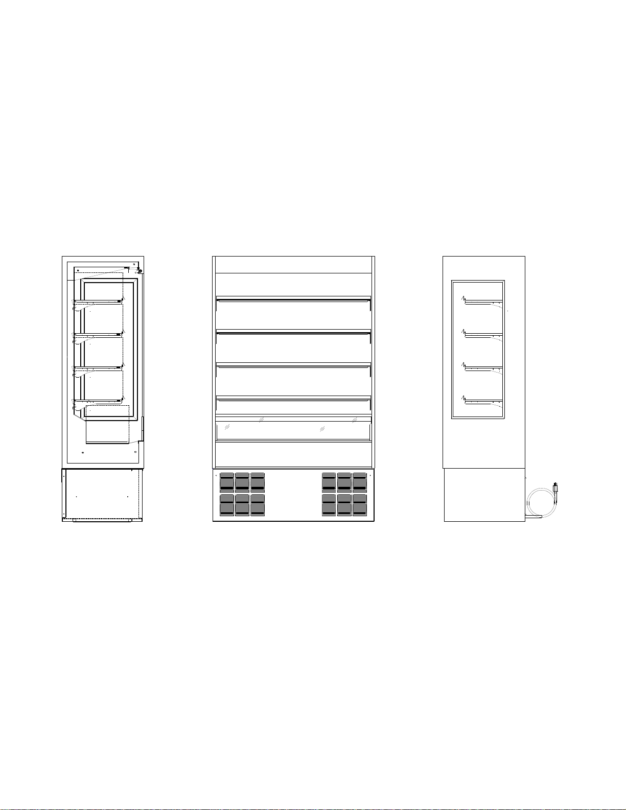
RSSL378, RSSL478, RSSL578, RSSL678
RSSL360, RSSL460, RSSL560, RSSL660
Self-Contained & Remote Models
NSSL378, NSSL478, NSSL578, NSSL678
Non-Refrigerated
INSTALLATION & OPERATION
INSTRUCTIONS
KEEP THIS MANUAL FOR FUTURE REFERENCE
Engineering and technical data are subject to change without notice.
FEDERAL INDUSTRIES 215 FEDERAL AVE Belleville, WI 53508
Toll Free 1(800) 356-4206 WI Phone (608) 424-3331 Fax: (608) 424-3234

Refrigerated Self-Serve Merchandiser (High Profile) Page 2
CONTENTS
INTRODUCTION .............................................................................................................4
WARNING LABELS & SAFETY INSTRUCTIONS..........................................................5
PRE-INSTALLATION PROCEDURES............................................................................6
Inspection For Shipping Damage......................................................................6
INSTALLATION INSTRUCTIONS...................................................................................6
Locating The Display Case.........................................................................................6
Grill Removal..............................................................................................................6
Removing Case From Shipping Skid..........................................................................7
Removing Packaging Material....................................................................................7
Leveling The Case......................................................................................................7
Condensate Evaporator..............................................................................................7
Lights..........................................................................................................................8
ELECTRICAL CONNECTION & GROUNDING INSTRUCTIONS...................................9
Electrical Supply Wiring ....................................................................................9
Grounding Requirements............................................................................9
Optional permanent connection ..................................................................9
OPERATING INSTRUCTIONS......................................................................................10
Initial Start-Up................................................................................................................10
Light Switch & Lights......................................................................................................10
LED Light Replacement.................................................................................................10
Digital Display.........................................................................................................................10
Placing Product in Case.................................................................................................10
Energy Saving Night Curtain..........................................................................................10
Electronic Temperature Control ....................................................................................11
Powering On Control......................................................................................................11
Adjusting Set Point.........................................................................................................12
Error Codes....................................................................................................................13
Optional Electronic Temperature Control ......................................................................14
Powering On Control......................................................................................................14
Adjusting Set Point.........................................................................................................15
Error Codes....................................................................................................................15
Temp Probe Common Resistance Chart.......................................................................16
ELECTRONIC CONTROL FUNCTIONALITY...............................................................17
Electronic Control............................................................................................17
Operation...................................................................................................17
Defrost Cycle..............................................................................................18
Control Factory Setting ..............................................................................18
Control Display................................................................................................19
Minimum Run Timer Feature ..........................................................................19
Maximum Run Timer Feature .........................................................................19

Refrigerated Self-Serve Merchandiser (High Profile) Page 3
REFRIGERATION OPERATION...................................................................................19
Self-Contained Refrigeration Operation..........................................................19
Dual Pressure Control ( Self-Contained Models Only )...................................19
Remote Refrigeration .....................................................................................20
Electronic Expansion Valve (EEV).............................................................20
Remote Refrigeration Operation .....................................................................21
CLEANING INSTRUCTIONS ........................................................................................22
Cleaning The Condenser Coil.........................................................................22
Cleaning The Condensate Pump....................................................................22
Cleaning The Acrylic Air Deflector...................................................................23
Daily Cleaning.................................................................................................23
Weekly Cleaning.............................................................................................24
SHELVES......................................................................................................................25
Installation & Removal.....................................................................................25
SERVICE INFORMATION.............................................................................................26
Pre-Service Checklist ...............................................................................................27
Special Service Situations ........................................................................................28
SALE & DISPOSAL ......................................................................................................28
Owner Responsibility................................................................................................28
REFRIGERATION & ELECTRICAL DATA .............................................................................29
RSSL378/360 ............................................................................................................29
RSSL478/460 ....................................................................................................30 & 31
RSSL578...........................................................................................................32 & 33
RSSL678...........................................................................................................34 & 35
NSSL378, NSSL478, NSSL578, NSSL678................................................................36
REPLACEMENT PARTS............................................................................................ 37 thru 44
RSSL DISPLAY AREA & VOLUME.........................................................................................45
WIRING DIAGRAMS................................................................................................... 46 thru 53

Refrigerated Self-Serve Merchandiser (High Profile) Page 4
INTRODUCTION
Thank you for purchasing a Federal Industries Merchandiser. This manual contains important instructions for
installing and servicing the RSSM, Refrigerated Self-Service Merchandisers. A repair parts list is also included in
the manual. Read all of these documents carefully before installing or servicing your case.
NOTICE
Read this manual before installing your case. Keep this manual and refer to it before doing any service
on the equipment. Failure to do so could result in personal injury or damage to the case.
NOTICE
Installation and service of the electrical components in the case must be performed by a licensed
electrician.
The portions of this manual covering components contain technical instructions intended only for persons
qualified to perform electrical work.
DANGER
Improper or faulty hookup of electrical components in the case can result in severe injury or death.
All electrical wiring hookups must be done in accordance with all applicable local, regional, or national
standards.
NOTE: UNIT MUST BE GROUNDED
REGISTRATION & SERIAL NUMBER
It’s important to keep a record of the model and serial number of your merchandiser for warranty and part
identification. Please write them here for your quick reference.
Register your product online! Visit our website at www.federalindustries.com and register your product
today.
Case Model__________________________ Serial Number______________________
We’re here to provide you with the best possible experience with your new product, however, we cannot cover
everything about your merchandiser in this manual, so if you have any additional questions or issues, please see
the SERVICE INFORMATION PAGE to find who you should contact.

Refrigerated Self-Serve Merchandiser (High Profile) Page 5
WARNING LABELS AND SAFETY
INSTRUCTIONS
This is the safety-alert symbol. When you see this symbol on your case or in the
manual, be alert to the potential for personal injury or damage to your equipment.
Be sure you understand all safety messages and always follow recommended precautions and safe
operating procedures.
NOTICE TO EMPLOYERS
You must make sure that everyone who installs, uses, or services your case is thoroughly
familiar with all safety information and procedures.
Important safety information is presented in this section and throughout the manual. The
Following signal words are used in the warning and safety messages:
DANGER: Severe injury or death will occur if you ignore the message.
WARNING: Severe injury or death can occur if you ignore the message.
CAUTION: Minor injury or damage to your case can occur if you ignore the message.
NOTICE: This is important installation, operation, or service information. If you ignore the
message, you may damage your case.
The warning and safety labels shown throughout this manual are placed on your Federal
Industries case at the factory. Follow all warning label instructions. If any warning or safety labels
become lost or damaged, call our customer service department at 1(800) 356-4206 for replacements.
This label is located on the back of the display case This label is located below the display pan.
and on the front of the case behind the access panel.
CAUTION
POWER BEFORE
RISK OF ELECTRIC
SHOCK DISCONNECT
91-12340
SERVICING UNIT.
CAUTION
HAZARDOUS MOVING PARTS
DO NOT OPERATE UNIT WITH
DISPLAY PANS REMOVED.
Refrigerated Self-Serve Merchandiser (High Profile) Page 6
PRE-INSTALLATION PROCEDURES
Inspection For Shipping Damage
You are responsible for filing all freight claims with the delivering truck line.
Inspect all cartons and crates for damage upon arrival. If there is damage to
shipping crates, cartons, or if a shortage is found, note this on (all copies) of
the Bill Of Lading prior to signing.
If damage is discovered when the case is uncrated, immediately call the delivering
truck line and follow-up the call with a written report indicating concealed damage to
your shipment. Ask for an immediate inspection of your concealed damaged item.
Crating material must be retained and shown to the inspector from the truck line.
INSTALLATION INSTRUCTIONS
Locating the Display Case NOTE: This case is designed for indoor use only.
The case should be located where it is not subjected to the direct rays of the sun,
heating ducts, grills, radiators, or ceiling fans, nor should it be located near open doors or
main door entrances. Avoid locations where there is excessive air movement or air disturbances
and avoid high humidity locations such as near cases with water misting or fogging devices.
The condenser air inlet is located in the front of the case. Do not block this inlet and do not
locate the air inlet near a source of heat. Clearance of 6” minimum must be maintained at the
back of the case for condenser discharge air. Clearance at the top of
the case should also be at least 8”.
Do not build this unit into an alcove and do not locate where condenser discharge air
cannot escape or where warm condenser air is allowed to re-circulate.
Grill Removal
WARNING: Electrical shock hazard. Do not operate unit with panels removed.
Must remove front and rear base grills for merchandiser installation. The front base grill
is secured with fast lead captive screws, and the rear base grill is secured with self
threading screws.
Both base grills must be replaced after merchandiser installation. Base grills must be
in place for proper operation of the merchandiser.
Refrigerated Self-Serve Merchandiser (High Profile) Page 7
Removing Case From Shipping Skid
CAUTION: If a Johnson bar or pry bar is used to move the case, make certain that
the case is lifted under the welded steel frame, and not by the end panels of the case.
Damage to the ends will result from lifting under the end panels.
Move the case as near as possible to the final location before removing it from the
shipping skid. Having removed the front and rear compressor compartment grills. Remove
the (three or four sets of bolts, nuts, and washers depending on case size) that secure the case to the
shipping skid. Discard these bolts, nuts, and washers.
Removing Packaging Material
Remove bubble wrap and packing material for all shelves, etc. If it is
necessary to remove tape residue from various materials, use cleaning
compounds recommended in the cleaning section of this manual.
Leveling the Case
The case must be level for proper drainage of defrost water to the condensate evaporator or
condensate pump.
Check the level of the case along the front rail and along the top of the display pan. Shim
under the case frame as needed to level the case. It is recommended that the leveled case be
sealed to the floor with an NSF Listed Sealant.
Condensate Evaporator
NOTICE: Steam from the condensate evaporator may be visible around the
base of the merchandiser during normal operation.
This merchandiser may be furnished with an electric condensate evaporator, or a
electric condensate pump. Plumbing connections are not required, unless
merchandiser is specifically ordered without a condensate evaporator or pump.
The condensate evaporator can be removed from the merchandiser and the
condensate drain can be plumbed to a external drain to conserve energy. To remove
the condensate evaporator, disconnect the wires at the condensate evaporator. This
must be done by a qualified electrician.
This is an open merchandiser and can produce a large amount of condensate water.
To ensure that adequate evaporator capacity is available, a high wattage heater is
used.
Make sure that the condensate drain line has not been dislodged during shipment and
that the drain trap terminates properly over the water reservoir.

Refrigerated Self-Serve Merchandiser (High Profile) Page 8
Lights
Standard Top Light
The case comes with one standard top light which is internally wired to the power
source. The light switch is located on the left top ceiling behind the air discharge honey comb.
Optional Shelf Lights
If optional shelf lights are furnished, make certain that the shelf light cords are completely
inserted into the sockets in the back panel and end of led lights or lights will not work
The power supply used on this case allows for removal of one or more shelf lights
without affecting the remaining lights.
When plugging or unplugging light cords, turn the light switch to the “off” position.
Refrigerated Self-Serve Merchandiser (High Profile) Page 9
ELECTRICAL CONNECTION AND
GROUNDING INSTRUCTIONS
Electrical Supply Wiring
DANGER: Improper or faulty hookup of electrical components in the
display case can result in severe injury or death.
THIS CASE MUST BE GROUNDED
Optional Permanent Connection
-Only a licensed electrician must perform all case electrical connections.
-All electrical wiring hookups must be done in accordance with all applicable local, regional, or
national electrical standards.
-A separate circuit for each display case is required to prevent other appliances on the same circuit
from overloading the circuit and causing malfunction.
-The electrical service must be grounded upon installation.
-See the electrical data plate located at the rear of the case for circuit load and wire current capacity.
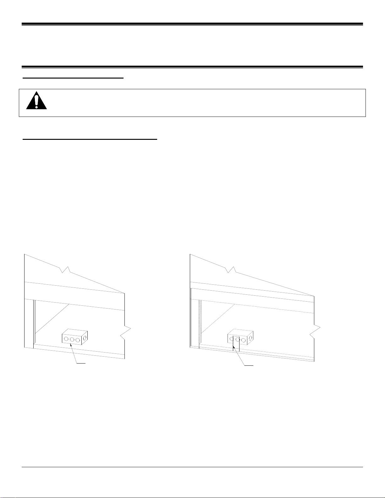
-Standard Base Electrical Connection: The electrical connection box is accessible from the rear of the
case. Power Supply Wiring can be routed through the floor of the base frame or through the access
hole in the rear of the unit. Remove electrical box cover to access electrical connections.
POWER IN BOX POWER IN ACCESS HOLE

Refrigerated Self-Serve Merchandiser (High Profile) Page 10
OPERATING INSTRUCTIONS
Initial Start-Up
-After completing the items in the installation section of this manual. The case is ready
to be put into service. On self-contained models, the service valves on the refrigeration
system are back-seated when the unit leaves the factory.
-RSSL cases are designed to operate at 40º to 41º F. under ambient conditions not to
exceed 75º F. and 55% relative humidity.
-Nearly all open refrigerated merchandisers operate better when loaded with product than
when empty. If a check is made of the case operating temperatures, perform this check with
product in the case.
-Open refrigerated merchandisers are not intended as storage refrigerators and will not “pull
down” room temperature products efficiently. Load case interior with pre-chilled product only.
Light Switch And Lights
The light switch is located in the ceiling. This switch operates the interior lights only. If optional
shelf lights are installed, they are also controlled by this switch.
Led Light Replacement
The light is attached to the shelf with plastic spring clips. To remove a light, un plug cord from
end of bulb and pull down.
When replacing lights, use direct equivalents to the original bulbs.
Digital Display
This unit is equipped with an electronic temperature control with Digital Display.
The Display show a number 1 thru 9 to indicate temperature level.
Placing Product In Case
Do not overload the case with product to a point where the top air discharge grill or the
bottom air intake grill are blocked, or where the air curtain created by the discharge air is
blocked.
LOAD CASE INTERIOR WITH PRE-CHILLED 38deg OR COLDER
PRODUCT ONLY.
Energy Saving Night Curtain
This unit is equipped with an energy saving night curtain.
The night curtain is located in the top inside front of the canopy.
To use the night-curtain pull down and latch on front panel just below the
clear acrylic air deflector when case is not in use.
NOTICE: This refrigerated display case is designed to operate
in a maximum environment of 75 DEG. F and 55% relative
humidity. Exceeding these limits will cause poor case
Refrigerated Self-Serve Merchandiser (High Profile) Page 11
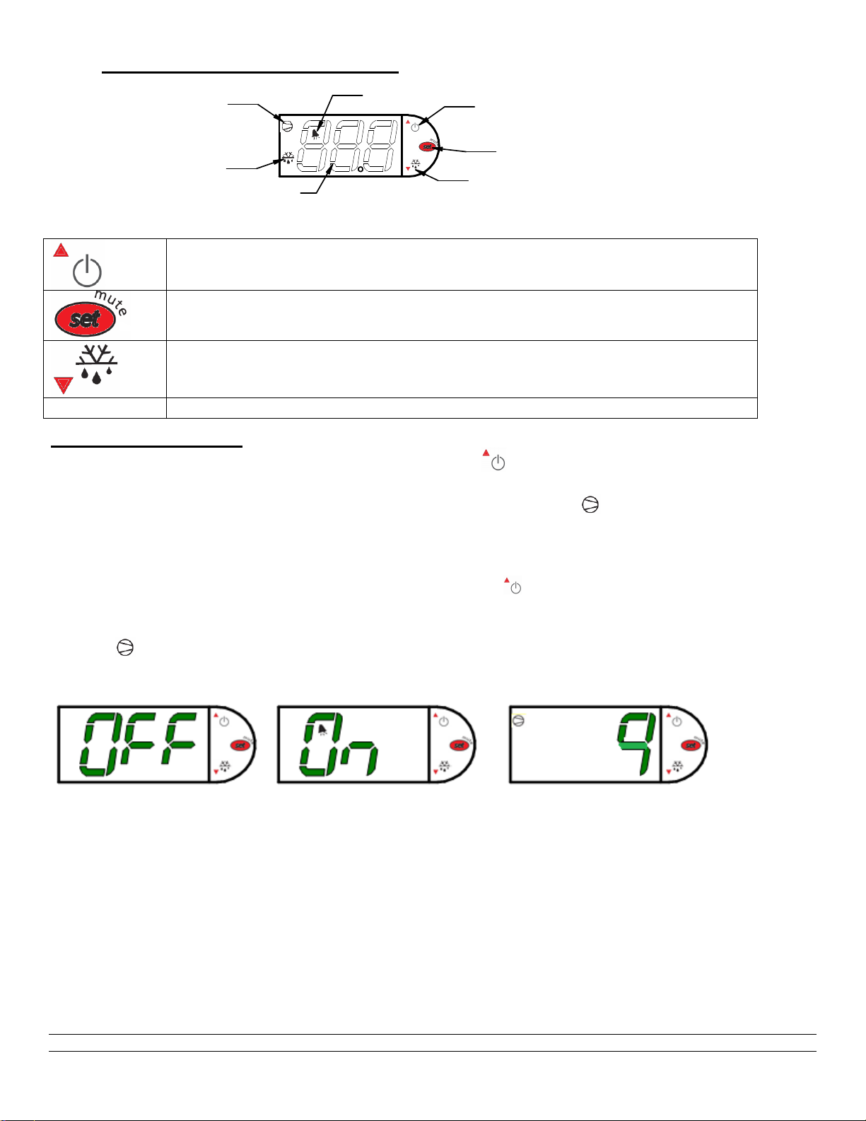
Electronic Temperature Control
DIGITAL DISPLAY
SET POINT ADJUST MODE
POWER TO CONTROL ON/OFF
AND SET POINT UP ADJUST
MANUAL DEFROST AND
SET POINT DOWN ADJUST
COMPRESSOR RUN
INDICATOR
DEFROST MODE INDICATOR
ALARM INDICATOR
Button Overview
Press and hold this button for three seconds to turn system on (if off) or off (if on).
Also used to adjust set point when in set point adjust mode
Press to enter set point adjust mode, confirm set point changes, and mute alarms.
Press and hold this button for three seconds to initiate a manual defrost (and cancel
defrost if initiated), also adjusts set point down when in set point adjust mode
Powering on control
To turn refrigeration control power on, press and hold for approx. three seconds. The display
will read “On” while the button is depressed. When the control powers on, the display will read the
current set point (a number “1” thru “9” ). The compressor run indicator will illuminate on the
display, meaning that the compressor is running. (Note: the control may already be in the on mode
when shipped from factory).
To turn refrigeration control power to off, press and hold for approx. three seconds. The
display will read “Off” while the button is depressed. When the control powers off the display will flash
back and forth between the relative current case temperature and “Off”. The compressor run
indicator will be off on the display. When refrigeration control is in the off-mode cabinet lights and
evaporator fans will still operate, but the compressor will not turn on causing the case to gradually
reach room temperature.

Refrigerated Self-Serve Merchandiser (High Profile) Page 12
Adjusting the set point
The set point is what determines how cold the display case will hold food and beverage. To adjust the
set point press and hold the button approx. three seconds until the display begins to flash a
number. Then press the use the button to scroll number up (colder) or press the button to
scroll number lower (warmer). There are nine (9) available set points numbers, the higher the number
of the set point, the colder the display case will run, with setting “9” being the coldest and setting “1”
being the warmest. Once you have chosen your desired setting press the button again to confirm
your choice.
Entering manual defrost mode
The control is programmed to automatically initiate a defrost by two different methods, involving time
and temperature, as outlined in the “Defrost Cycle” section (Pg. Error! Bookmark not defined.) of
“ELECTRONIC CONTROL PARAMETERS AND EXPLANATION OF OPERATION.” While it is
uncommon that the automatic defrost cycles would insufficiently defrost the case, a Manual Defrost
mode is available if this situation arises. Note: The control will not allow the initiation of a manual
defrost within 30 minutes of completion of another defrost cycle, manual or automatic.
To initiate a manual defrost press and hold the button approx. three seconds. The control will
read “dEF” while the button is being held. The defrost is initiated when the defrost mode indicator
illuminates on the display. The control display will then return to reading the case temperature. When
the defrost mode indicator turns off the defrost is complete and the compressor will turn back on
illuminating the compressor run indicator .

Refrigerated Self-Serve Merchandiser (High Profile) Page 13
Error codes
It is possible for error codes to be displayed on the control screen. In the event of a malfunction an alarm will
sound and the alarm indicator will be displayed on the display. An error code or codes will flash
intermittently on the display. If there are multiple codes, the display will continuously cycle through them. The
following photo shows error code “E0” as an example.
Mute: You may mute the alarm by pressing and releasing the wrench button. The red ringing bell and all error
codes will still be displayed. When the fault is remedied the control will return to normal operation and will
automatically clear the codes from the display.
Carel Control
EO = Air sensing probe - Open or shorted
E1 = Evap. coil probe - Open or shorted

Refrigerated Self-Serve Merchandiser (High Profile) Page 14
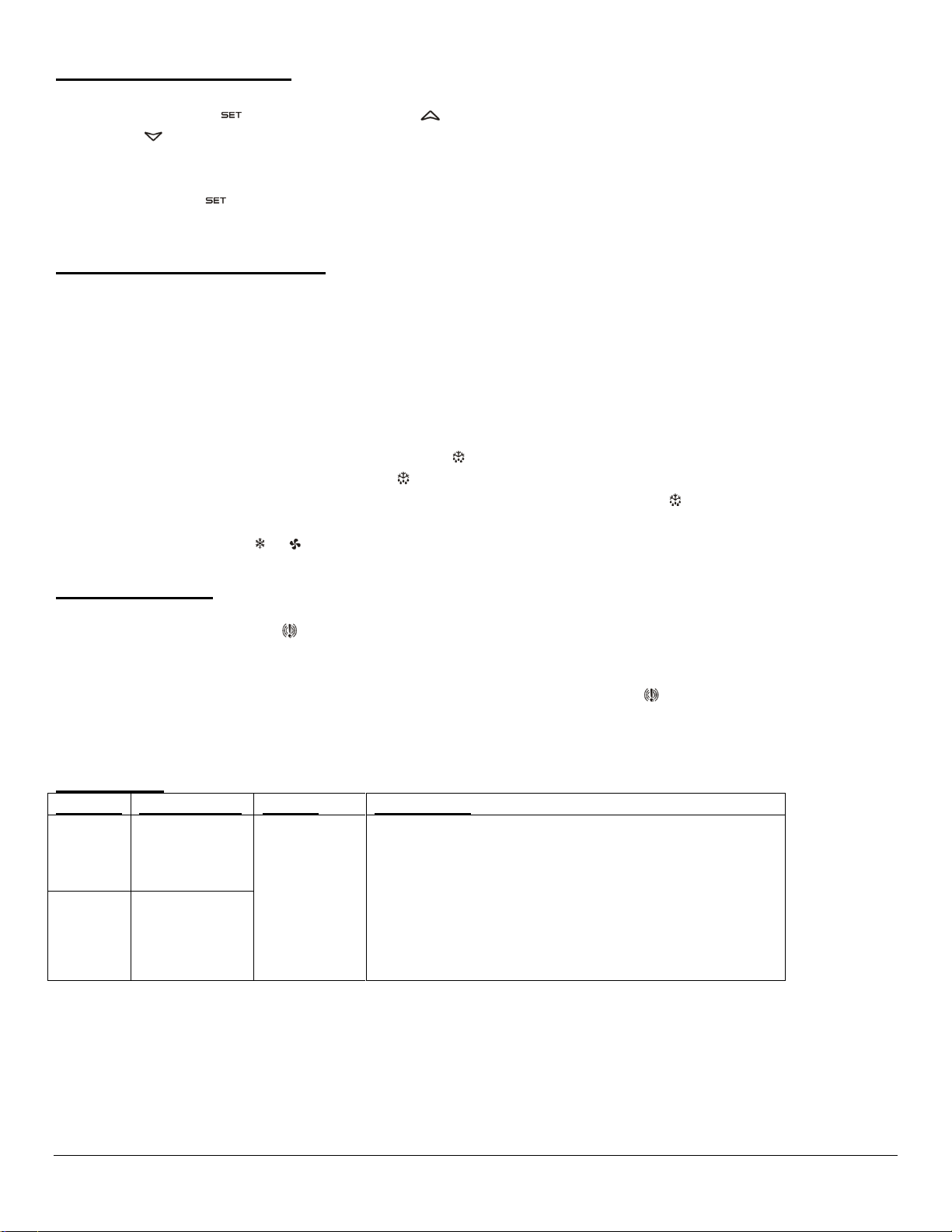
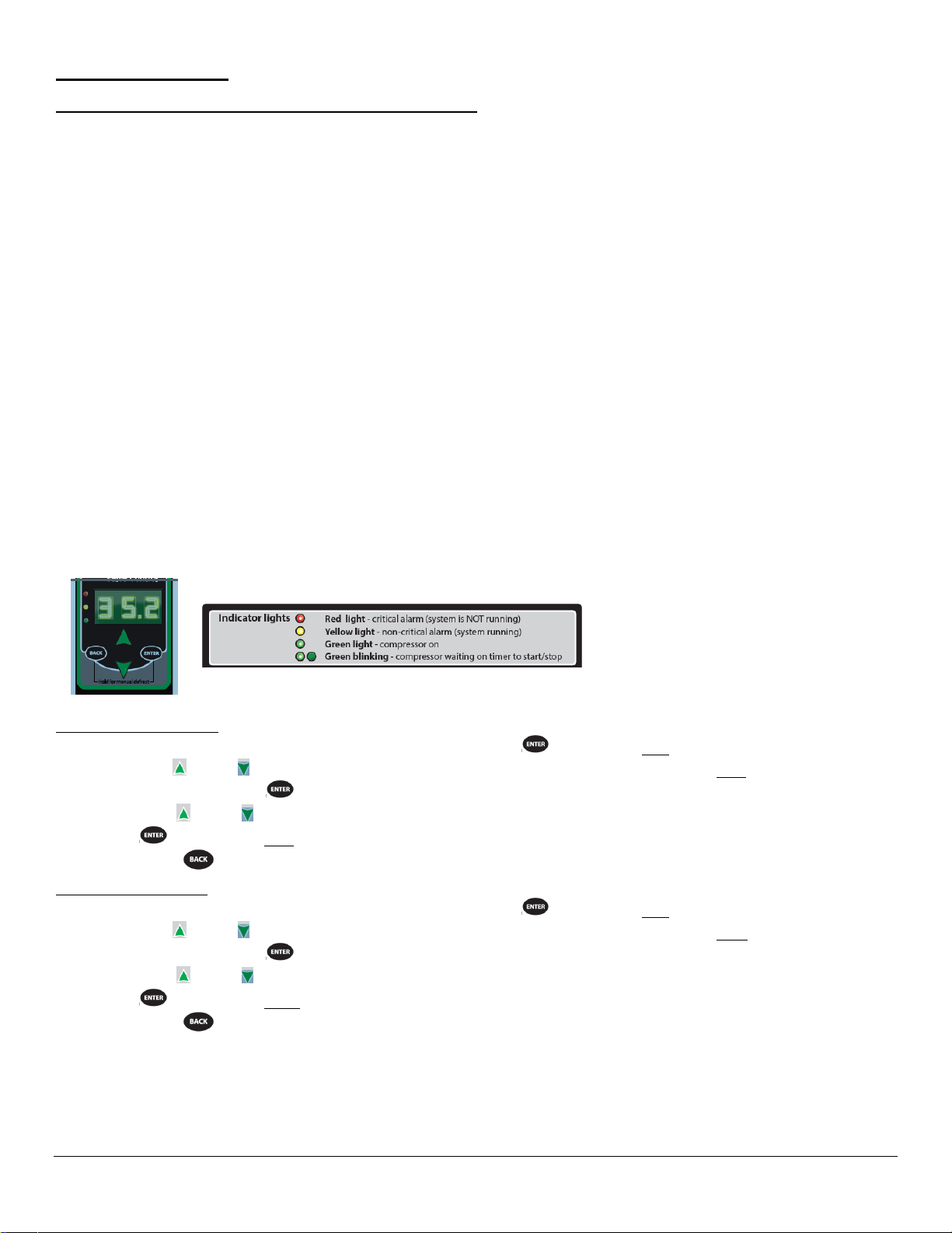
Alternate Electronic Temperature Control
Power on/off: Press and hold to turn system on or off.
Set: Press and hold to enter the set point adjustment menu.
Defrost: Press and hold to initiate a manual defrost.
Up: Change set points when in set point adjustment menu.
When not in set point menu, shows maximum temperature of
air discharge probe.
Down: Change set points when in set point adjustment menu.
When not in set point menu, shows minimum temperature of
air discharge probe.
Display indication symbols
On
Compressor on
Flashing
Minimum compressor off time in progress
On
Unit in defrost mode
Flashing
Defrost delay
On
Condenser fan running
Flashing
Minimum condenser fan off time in progress
On
Alarm occurring. See error code section below.
On
Indicates temperature unit of measure.
Powering on control
To turn refrigeration control power on, press and hold “ ” for approx. three seconds. The display
will read the probe temperature when on. When the control powers on, the display will read the
current probe temperature. The compressor and condenser fan run indicators ( & ) will illuminate
on the display, meaning that the compressor and condenser fan are running. (Note: the control may
already be in the on mode when shipped from factory).
To turn refrigeration control power to off, press and hold “ ” for approx. three seconds. When the
control powers off the display will read “OFF”. When refrigeration control is in the off-mode cabinet
lights and evaporator fans will still operate, but the compressor will not turn on causing the case to
gradually reach room temperature.
Refrigerated Self-Serve Merchandiser (High Profile) Page 15
Adjusting the set point
The set point is what determines how cold the display case will hold food and beverage. To adjust the
set point press the “ ” button. Then press “ ” button to increase the set point number (colder) or
press the “ ” button to decrease the set point number (warmer). There are nine (9) available set
points numbers, the higher the number of the set point, the colder the display case will run, with
setting “9” being the coldest and setting “1” being the warmest. Once you have chosen your desired
setting press the “ ” button again to confirm your choice. The control cutout temperature for the
selected setpoint will briefly be displayed if the setpoint was changed.
Entering manual defrost mode
The control is programmed to automatically initiate a defrost by two different methods, involving time
and temperature, as outlined in the “Defrost Cycle” section (Pg.15) of “ELECTRONIC CONTROL
FUNCTIONALITY.” While it is uncommon that the automatic defrost cycles would insufficiently
defrost the case, a Manual Defrost mode is available if this situation arises.
Note: The control will not allow the initiation of a manual defrost within 30 minutes of completion of
another defrost cycle, manual or automatic.
To initiate a manual defrost press and hold the “ ” button approx. three seconds. The defrost is
initiated when the defrost mode indicator illuminates on the display. The control display will then
return to reading the probe temperature. When the defrost mode indicator turns off the defrost is
complete and the compressor will turn back on automatically and the compressor and condenser fan
indicator will be shown ( & ).
Control Alarms
It is possible for error codes to be displayed on the control screen. In the event of a malfunction an alarm will
sound and the alarm indicator will be displayed. An error code or codes will flash intermittently on the
display. If there are multiple codes, the display will continuously cycle through them.
Mute: You may mute the alarm by pressing any button. The red alarm symbol and all error codes will still be
displayed. When the fault is remedied, the control will return to normal operation and will automatically clear
the codes from the display.
Error Codes
Display
Description
Cause
Resolution
“P1”
Air discharge
temperature
probe failure
Probe signal
is
interrupted
or short-
circuited
•Check to ensure probe wires and quick disconnect are secure
in control.
•Check probe resistance to table below. If 0 resistance is
present, check wiring insulation. If infinite resistance is
present, check for breaks in wiring (meter will likely read
overload or very high in the mega-ohm range).
•Ensure that probes are wired per the wiring diagram provided.
Replace probe if other remedies fail, or if probe resistance
deviates from “Table 3” below.
“P2”
Defrost
temperature
probe failure
Refrigerated Self-Serve Merchandiser (High Profile) Page 16
TEMPERATURE PROBE COMMON RESISTANCE CHART
Probe Temp
Maximum
Resistance [Ω]
Normal
Resistance [Ω]
Minimum
Resistance [Ω]
32°F(0°C)
27.83
27.28
26.74
77°F(25°C)
10.1
10
9.9
212°F(100°C)
1
0.97
0.94
Refrigerated Self-Serve Merchandiser (High Profile) Page 17
ELECTRONIC CONTROL FUNCTIONALITY
Electronic Control
This unit is equipped with an electronic temperature control. The control parameters are set at
the factory and cannot be manually changed in the field. Control parameter changes can only
be made by downloading a new set of parameters using a program chip supplied by Federal
Industries. The pre-set control parameters are listed on the chart in the Settings Chart below.
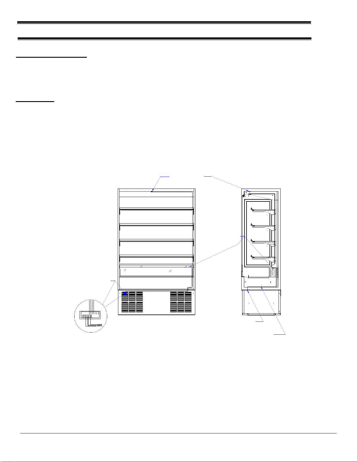
Operation
The control uses two sensors, one located in the air stream and one located on the evaporator coil.
The sensor located in the air stream is referred to as the temperature control sensor. The sensor
located on the evaporator coil is referred to as the coil sensor.
The temperature control sensor is located inside the top air duct behind the honeycomb material and
is labeled (TEMP). The sensor location is critical for proper operation on the unit. Do not move or
relocate this sensor.
The coil sensor is strapped to the evaporator coil and is labeled (DEFROST). This sensor location is
critical for proper operation of the unit. Do not move or relocate this sensor.
CONTROL LOCATED BEHIND
BASE FRONT PANEL
TEMP SENSOR BULB
LOCATED LEFT OF CENTER
IN AIR DISCHARGE DUCT
DETAIL OF TEMP CONTROL
W/SENSOR WIRES ATTACHED
PROBE WIRES ROUTED THRU
TUB FLOOR AND UP BACK OF CASE
PROBE WIRES MOUNTED TO INSIDE
FLANGE OF TOP FRONT BASE RAIL
W/CABLE HOLDERS
DEFROST SENSOR PROBE LOCATION
3" IN FROM COIL HEADER PLATE
MOUNTED TO CENTER COIL TUBE
WITH (2) CABLE TIES
14GA.
TEMP.PROBE PBI
DEFROS TPROBE PB2
14GA.
18GA.
18GA.
BLK
OR
RED
WW
R
BLK
Y
BLK
CAREL
CONTROLLER
11 109 8
76 54
OPTIONAL CONTROL
BLK
OR
RED
BLK
OR
RED
The temperature control is set to cut in at 39 degrees F. The Temp control cuts out at 24 degrees F at
the coldest setting’ COLD’ and 34 degrees F at the warmest setting, ‘1’ on the control readout.
Refrigerated Self-Serve Merchandiser (High Profile) Page 18
Defrost Cycle
The electronic control is programmed to initiate defrost by two different methods. There are (3) programmed
defrost cycles in the control which will initiate a defrost cycle every 8 hours. The unit does not have a time
clock so the defrost cycles cannot be set for any specific time of day.
The electronic controller uses time to initiate the defrost cycle, and temperature to terminate the defrost cycle.
The controller also has an ‘On demand’ defrost feature that will initiate a defrost cycle when the temperature
differential between the evaporator temperature and the air temperature is more than 15 degrees for 5 minutes
after 30 minutes into the refrigeration cycle.
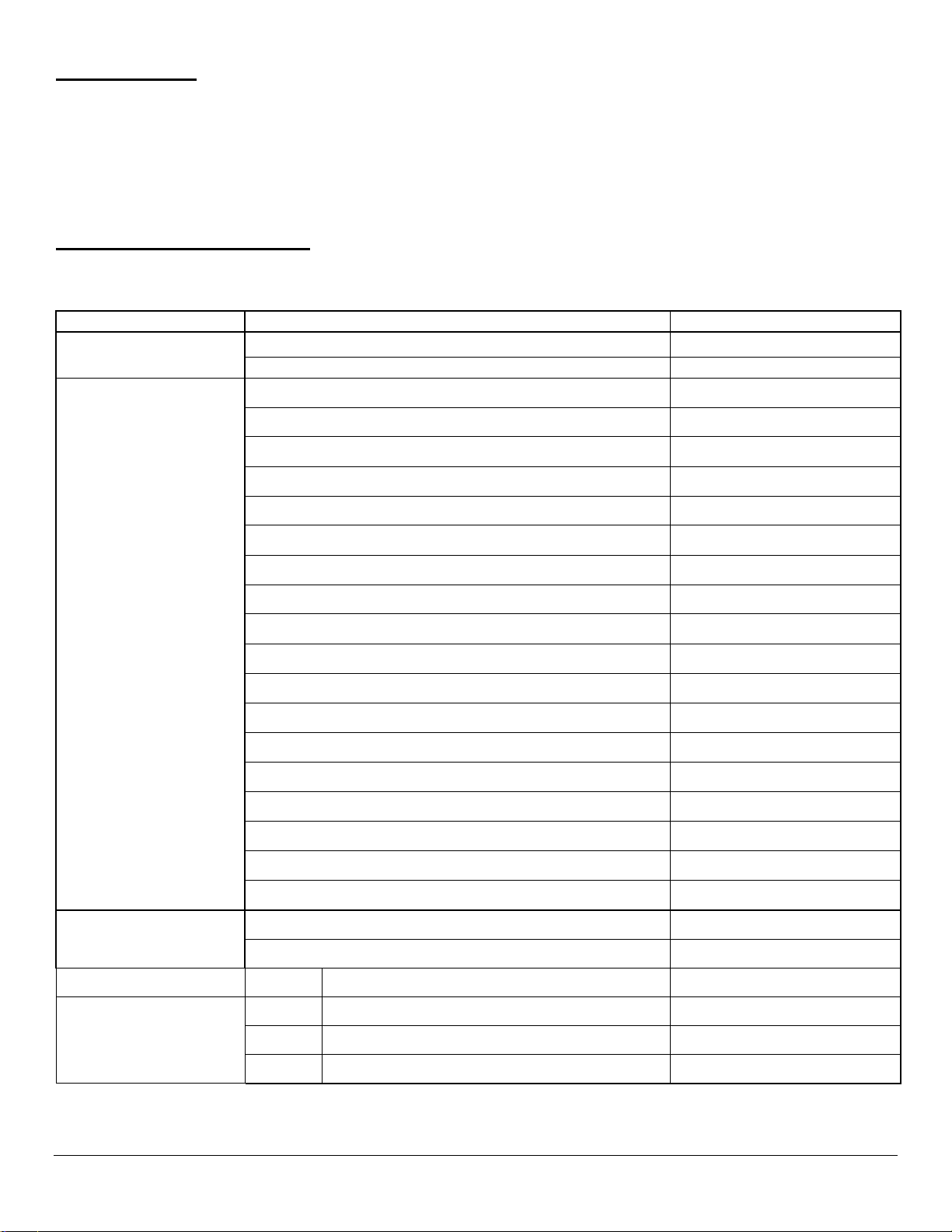
Control Factory Settings
The control parameters are set at the factory and cannot be manually changed in the field. Control parameter
changes can only be made by downloading a new set of parameters using a program chip supplied by Federal
Industries
TAB
PARAMETER DESCRIPTION
RSSM
CONFIGURATION
Controller Operation Temperature Units
Degrees Fahrenheit
Defrost Termination Method
Evaporator Sensor
SET-POINTS
Setting “1” Cut-In (Warmest Setting)
39ºF
Setting “1” Cut-Out (Warmest Setting)
34ºF
Setting “2” Cut-In
39ºF
Setting “2” Cut-Out
32ºF
Setting “3” Cut-In
39ºF
Setting “3” Cut-Out
31ºF
Setting “4” Cut-In
39ºF
Setting “4” Cut-Out
27ºF
Setting “5” Cut-In
39ºF
Setting “5” Cut-Out
25ºF
Setting “6” Cut-In
39ºF
Setting “6” Cut-Out
23ºF
Setting “7” Cut-In
39ºF
Setting “7”Cut-Out
22ºF
Setting “8” Cut-In
39ºF
Setting “8” Cut-Out
21ºF
Setting “9” Cut-In (Coldest Setting)
39ºF
Setting “9” Cut-Out (Coldest Setting)
20ºF
COMPRESSOR
Compressor Minimum On Time
5 minutes
Compressor Maximum On Time
60 minutes
DEFROST
Defrost Termination Temperature
45ºF
DEFROST
Time to First Defrost (hh:mm)
8 hr
Time to subsequent Defrost
8 hr
Defrost Max Duration
30 minutes

Refrigerated Self-Serve Merchandiser (High Profile) Page 19
Control Display
The control display is located in the unit base. It is programmed to display the current set point
associated with the control sensor located inside the air duct at the top of the case.
Minimum Run Timer Feature
The unit controller is programmed to have the condensing unit run a minimum of 5 minutes,
regardless of the control temp being satisfied. If the temperature control reaches the cut out set point
before 5 minutes, the minimum run time setting in the control will keep the unit in a run cycle mode
until the timer reaches 5 minutes. The refrigeration cycle will be off until the temperature control cut in
temperature is reached.
This timer typically comes into effect in low ambient conditions where the unit may cycle too
frequently to maintain proper product temperature.
Maximum Run Timer Feature
The unit controller is programmed to have the condensing unit run a maximum of 60 minutes.
If the unit has not reached cut out temperature setting in 60 minutes, the unit goes into on off cycle.
This typically comes into effect in high ambient temperature and relative humidity conditions.
REFRIGERATION OPERATION
Self-Contained Models
Refrigeration R404A Charge Prior To 01/01/2020
See Refrigeration
And Electrical Data
Pages
Refrigeration R449a Charge After 01/01/2020
See Refrigeration
And Electrical Data
Pages
The self-contained models are shipped from the factory with a completely operational 404A
refrigeration system and require no modifications or adjustments upon installation. Case must be
installed as per the installation section of this manual to provide proper condensing air cooling.
Self-Contained Refrigeration Operation
The unit temperature is controlled by the Electronic control outlined in the control section of this
manual.
Note: The condenser fan is factory wired to run continuously.
Dual Pressure Control (Self-Contained Models Only)
The dual pressure control is used as a safety device and is factory set. The pressure control
works on a differential. The low-pressure side is a safety to protect the compressor in the case
of refrigerant loss. The high-pressure side is a safety to protect from system failure causing too
high of system pressure.
The high side of the pressure control is factory set to 400psi and is not adjustable.
Low side setting for the R404a cases are set at 40psi differential for the cutout and 60psi for
the cut-in.
Refrigerated Self-Serve Merchandiser (High Profile) Page 20
Remote Operation
Electronic Expansion Valve (EEV) After 1/20
A traditional TXV uses springs and a temperature bulb to open and close a valve port that controls the flow of
refrigerant entering the evaporator coil. An electronic expansion valve (EEV) controls the refrigerant flow much
more precisely, increasing the performance and efficiency of the refrigeration system. The EEV controls the
flow of Refrigerant by opening and closing the valve port based on the response to signals sent to the EEV by
an electronic controller. The electronic Control bases these signals by processing information provided from a
temperature sensor and pressure transducer located on the discharge side of the evaporator coil.
These sensors monitor the evaporator superheat and protects the compressor from any liquid flood back under
low superheat conditions.
EEV Controller Settings
The electronic expansion valve controller also allows the use of different types of refrigerants without the need
to change the expansion valve.
The controller is set from the factory to run on R449a refrigerant and will not need any changes to the control
unless another refrigerant is used.
Note: Check your State and Local regulations for approved refrigerants for your install location. Federal
Industries is not liable for any alternate refrigerants used.
The control is located on the base floor on the left-hand side front view .
Note: Never change any of the other setting other than the refrigerant type. It may also be necessary to
change the superheat setting only when using a different refrigerant.
Changing Refrigerant
•Access the set point mode by pressing and holding the button until Ctl displays on the screen.
•Use the up or down arrows to advance through the available set points until rFG displays on the
screen and press the botton.
•Use the up or down arrows until the desired refrigeration displays on the screen and press and hold
the button until rFG once again displays on the screen.
•Press the to return to escape the settings menue.
Changing Superheat
•Access the set point mode by pressing and holding the button until Ctl displays on the screen.
•Use the up or down arrows to advance through the available set points until SSP displays on the
screen and press the botton.
•Use the up or down arrows to set the desired superheat displays on the screen and press and hold
the button until SSP once again displays on the screen.
•Press the to return to escape the settings menue.
This manual suits for next models
11
Table of contents
Other FEDERAL INDUSTRIES Merchandiser manuals


