FEDERAL PACIFIC AUTO-JET AJS Installation instructions

1075 Old Airport Road • Bristol, VA 24201 Phone (276) 669-4084 • FAX (276) 645-8206 • www.federalpacic.com • ISO9001:2015
SECTION IB-3A-310A
INSPECTION & MAINTENANCE RECOMMENDATIONS
JUNE 2021
PAGE 1
TYPE AJS — AUTO-JET®SWITCHES
15kV • 25kV • 38kV
INSPECTION & MAINTENANCE RECOMMENDATIONS
The procedures required for operation of the Federal Pacic Auto-
jet® Load-Interrupter Switches. The inspection and maintenance
recommendations covered in this bulletin are expected to be
performed in conjunction with a review of IB-3A-310. This bulletin
does not cover all the detailed and specic operational procedures
and checks. In addition, these instructions are not intended as a
substitute for the user’s standard operating practices and procedures.
A copy of Instruction Bulletin Section IB-3A-310 can be printed from
the internet at www.federalpacic.com.
When cleaning components, NEVER use any industrial strength
cleaners. NEVER apply lubricants to the probe contact or the
tulip contact which are the interrupting contacts. NEVER use any
solvent-based or ammable products on any components in the
pad-mounted switchgear. Solvents and ammable products can
attack non-metallic components of the equipment and reduce
electrical and mechanical properties.
Maintenance
Federal Pacic switchgear does not require routine mechanical
or electrical maintenance. However, the following are some
recommendations for enhancing continued service of the equipment.
Before Opening the Switchgear
The following inspection and maintenance procedures must be
performed with the unit completely de-energized and isolated from
voltage. Any attempt to perform the inspection and maintenance
with the unit energized may result in electrical arc ash that can
cause equipment damage, personal injury or death.
WARNING
DANGER
© 2021 Electro-Mechanical Corporation
Qualied Persons
The equipment covered by this publication must be selected for a specic
application and it must be operated and maintained by Qualied Persons
who are thoroughly trained and knowledgeable in the installation, operation,
and maintenance of underground power distribution equipment along with
the associated hazards that may be involved. This publication is written only
for such qualied persons and is not intended to be a substitute for adequate
training and experience in safety procedures for this type of equipment.
Proper installation is the responsibility of the operating and construction
personnel and the utility performing and authorizing the work. Completion
of these instructions implies no further warranty by the manufacturer.
A Qualied Person is dened in the National Electrical Code (NEC/NFPA-
70) as:
One who has skills and knowledge related to the construction and operation
of the electrical equipment and installations and has received safety training
to recognize and avoid the hazards involved.
The specic electrical safety training requirements to be considered a
qualied person are detailed in NFPA-70E, Article 110.1(D), Employee
Training. Some of the requirements from the 2012 edition are shown below.
For the specic detailed training requirements for a Qualied Person make
certain to refer to the most recent applicable edition.
These training requirements would include, but are not limited, to the
following key points:
• The skills and techniques necessary to distinguish exposed energized
parts from other parts of electrical equipment.
• The skills and techniques necessary to determine the proper approach
distances corresponding to the voltages to which the qualied person will
be exposed.
• The proper use of the special precautionary techniques, personal protective
equipment, insulating and shielding materials, and insulated tools for
working on or near exposed energized parts of electrical equipment.
• Tasks performed less often than once per year have additional training
requirements.
These instructions are intended only for such qualied persons. They are not
intended to be a substitute for adequate training and experience in safety
procedures for this type of equipment. Additionally, the recommendations
in this instruction bulletin are not intended to supersede or to take the place
of established utility safety guidelines and established practices. If there
is any question, consult with your foreman or supervisor, as appropriate.
Please refer to OSHA 29 CFR 1910.399 and NFPA 70E Articles 100 and 110.
WARNING
1075 Old Airport Road • Bristol, VA 24201 Phone (276) 669-4084 • FAX (276) 645-8206 • www.federalpacic.com • ISO9001:2015
SECTION IB-3A-310A
INSPECTION & MAINTENANCE RECOMMENDATIONS
JUNE 2021
PAGE 2
1. Exercising
Yearly mechanical exercising of the switch is recommended.
Refer to Instruction Bulletin Section IB-3A-310 for information on
operating the switch.
The switchgear must be completely de-energized from all sources
before any attempt is made to enter switchgear. Follow normal
system operating practices to de-energize the unit, test for voltage
and ground the unit before any work is performed.
2. Cleanliness
Check for cleanliness generally, but particularly for accumulation
of any foreign material on insulators and barriers.
Barriers and insulators can be cleaned with a non-alcohol and
non-solvent based cleaner that does not leave any residue when
dry. Residue must be removed.
3. Barrier Removal
When removing barriers, care must be taken to keep the barrier clean
and dry. Contamination on barrier can lead to tracking and arcing.
Clean off any contamination with a non-alcoholic and non-solvent
based cleaner that does not leave any residue.
Removal of the barriers is readily accomplished as follows:
a. Completely disconnect the unit from all power sources.
b. Open main door.
c. Test for voltage, and ground the unit using the user's standard
practice procedures and using grounding clamps suitable for the
short-circuit rating of the equipment.
4. Switch Operation
Do not put any lubricant on switch probe or puffer contacts. Refer to
Section 6 "Lubrication".
Check switch for proper operation refer to Instruction Bulletin
IB-3A-310. If the switch is closed on a short circuit within the
fault closing rating and the short circuit is cleared by circuit
breakers or fuses, the switch will not sustain damage which would
require major repairs. However, the switch should be inspected
before returning to service to determine switch condition. See
Lubrication.
5. Replacement Parts
If parts or labels are required they may be ordered by contacting
Federal Pacic at 276-669-4084 or your local Federal Pacic
Manufacturer's Representative. A directory of the representatives
can be found at www.federalpacic.com. If parts are ordered, the
unit serial number and date of manufacture must be provided
along with the part description.
NOTICE
CAUTION
WARNING
6
. Lubrication
When maintenance is performed, check for lubrication at the
locations pictured on Page 3.
7
Verify Security Devices
Verify the operational integrity of security devices such as door
latches, penta-head bolts, hinges and key-interlock systems. Make
certain padlocks are properly installed on all doors and covers.
8.
Specication
Torque Value: For bus bar connections, apply 50ft-lbs torque
to 1/2-13 UNC 18-8SS (or equivalent) hex bolts. For other bolted
connections, refer to factory.
High-Pot Test Value: After cleaning and restoring equipment,
apply as follows:
15.5 kV - 75% of 36kV for one (1) minute
25 kV - 75% of 60kV for one (1) minute
38 kV - 75% of 80kV for one (1) minute
WARNING
1075 Old Airport Road • Bristol, VA 24201 Phone (276) 669-4084 • FAX (276) 645-8206 • www.federalpacic.com • ISO9001:2015
SECTION IB-3A-310A
INSPECTION & MAINTENANCE RECOMMENDATIONS
JUNE 2021
PAGE 3
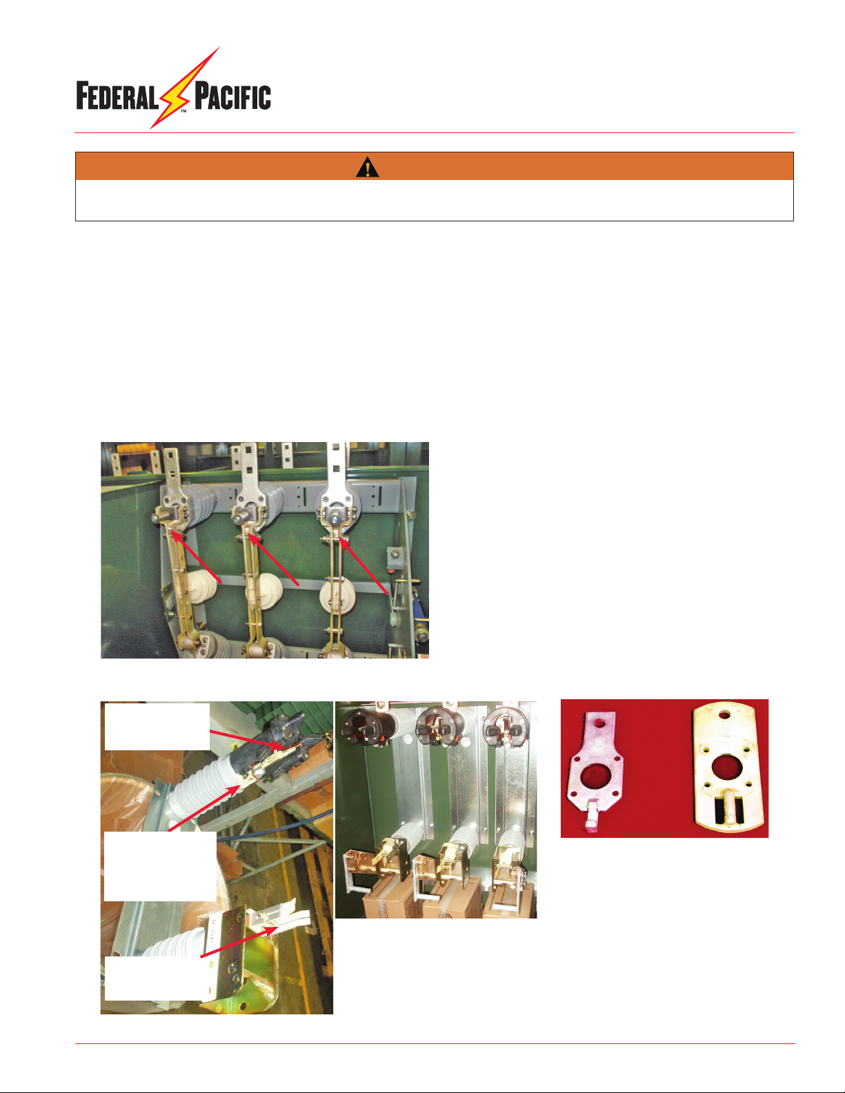
Figure 2. Lubrication points on fuse mounting
include three contact locations, namely, the main
contact, forward contact and fuse hinge contacts.
Fuse-hinge contacts
that engage the fuse
contact ferrule
Contact interface at
stationary main contact
casting (or rod on main-
contact plate for older
designs)
Forward contacts
that engage the fuse
contact rod
Figure 3. View shows present cast fuse main con-
tact at left and previous main contact, which was a
weldment, at right (removed from fuse mounting).
LUBRICATE ONLY:
1. On the switch main-contact stab. See Figure 1.
2. On the contact interface at the fuse-mounting stationary main contact. See Figure 2.
3. On the forward contact that engages the fuse contact rod and on the fuse hinge contacts that engage the fuse contact ferrule The contact
rod and fuse ferrule on the fuse assembly. Refer to fuse manufacturer's instructions.
4. DO NOT LUBRICATE ANY OTHER AREAS.
5. If lubrication is required apply a coating of NYE Rheolube 363, which is the only approved lubricant.
Figure 1. Lubricate only the interface between the main-contact stab and the
switch blade marked by arrows.
Lubrication is NOT required on any other surfaces than the locations identied below. Applying lubrication in other areas may reduce
mechanical and electrical performance. DO NOT OVER LUBRICATE!
WARNING

1075 Old Airport Road • Bristol, VA 24201 Phone (276) 669-4084 • FAX (276) 645-8206 • www.federalpacic.com • ISO9001:2015
SECTION IB-3A-310A
INSPECTION & MAINTENANCE RECOMMENDATIONS
JUNE 2021
PAGE 4
Every effort is made to ensure that customers receive an up-to-date instruction manual on the use of Federal Pacic products; however, from time to
time, modications to our products may without notice make the information contained herein subject to alteration.
© 2021 Electro-Mechanical Corporation
Notes:
Other FEDERAL PACIFIC Switch manuals


Popular Switch manuals by other brands


PowerShield
PowerShield PSMBS2K quick guide

Elko
Elko iNels RFSAI-62B-SL quick start guide

Elnur Gabarron
Elnur Gabarron G CONTROL HUB Installation instructions and user guide

Vivotek
Vivotek AW-IHT-1271 Quick installation guide

Cisco
Cisco 11154 - CSS - Switch datasheet

D-Link
D-Link DGS-1228P reference guide


