FEDERAL PACIFIC PSE User manual

601 Old Airport Road • Bristol, VA 24201 Phone (276) 669-4084 • FAX (276) 669-1869 • www.federalpacific.com • ISO9001:2015
SECTION IB-2A-210
INSTALLATION & OPERATION INSTRUCTIONS
TYPE PSE PAD-MOUNTED SWITCHGEAR
NOVEMBER 2017, REV 4.2
PAGE 1
TYPE PSE
DEADFRONT PAD-MOUNT SWITCHGEAR
15kV • 25kV • 35kV
INSTRUCTIONS
For Installation and Operation
QUALIFIED PERSONS.................................................................................................... 2
SAFETY INFORMATION ................................................................................................ 2
INTRODUCTION.............................................................................................................. 3
Receiving.................................................................................................................... 3
Handling ..................................................................................................................... 3
Storage ....................................................................................................................... 3
GENERAL DESCRIPTION .............................................................................................. 3
SECURITY FEATURES.................................................................................................... 3
AUTO-LATCH DOOR ...................................................................................................... 4
Features...................................................................................................................... 4
Operation.................................................................................................................... 4
INSTALLATION ............................................................................................................... 5
Placement of unit...................................................................................................... 5
Customer cable connections.................................................................................. 5
SWITCH DESCRIPTION................................................................................................. 5
Switch operating sequence.................................................................................... 6
Switch ratings ........................................................................................................... 7
Operating the Auto-jet®II switch.............................................................................................................................7-8
FUSE DESCRIPTION....................................................................................................... 9
Fuse removal ........................................................................................................9-12
Fuse ratings ............................................................................................................. 13
MAINTENANCE............................................................................................................ 14
OPTIONAL FEATURES ................................................................................................. 14
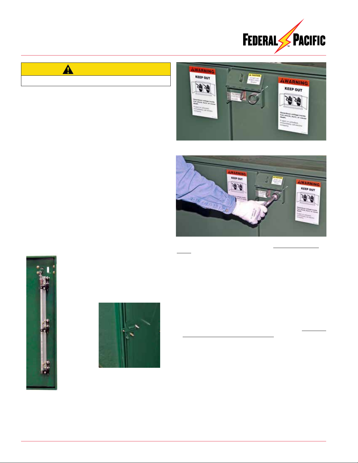
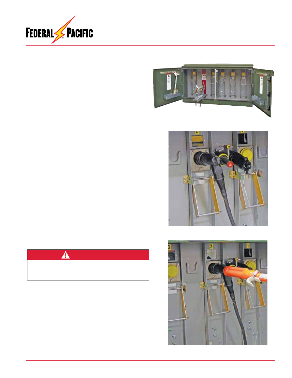
Figure 2. Switch compartment of Federal Pacific PSE pad-
mounted switchgear. Storage for fuse assemblies is on fuse
side, better facilitating fuse changing procedures. Wide-view
windows and broad blades provide improved visibility to make
it easier to verify switch position, even behind cables and
elbows, while the open/closed labels serve to further enhance
this user-friendly design.
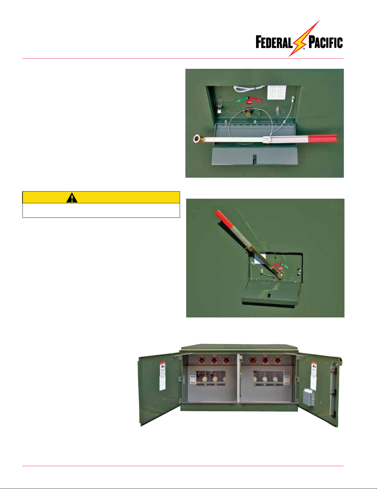
Figure 1. Fuse compartment of Federal Pacific PSE pad-
mounted switchgear. Spacing between fuse panels is
adequate to accommodate a horizontal feed-thru standoff
bushing - and there is a viewing window directly in front of
each fuse, making blown-fuse targets fully visible. Doors
feature three-point automatic, self-latching door latches. The
captive security bolt rotates 60° in either direction (clockwise
or counter-clockwise) to open. Do not use power tools. See
page 4 for additional information
Qualified Persons
© 2014 Electro-Mechanical Corporation
These training requirements would include, but are not limited, to the
following key points:
• The skills and techniques necessary to distinguish exposed energized
parts from other parts of electrical equipment.
• The skills and techniques necessary to determine the proper approach
distances corresponding to the voltages to which the qualified person
will be exposed.
• The proper use of the special precautionary techniques, personal pro-
tectiveequipment, insulatingand shieldingmaterials, andinsulated tools
for working on or near exposed energized parts of electrical equipment.
• Tasks performed less often than once per year have additional training
requirements.
These instructions are intended only for such qualified persons. They
are not intended to be a substitute for adequate training and experience
in safety procedures for this type of equipment. Additionally, the recom-
mendations in this instruction bulletin are not intended to supersede or
to take the place of established utility safety guidelines and established
practices. If there is any question, consult with your foreman or supervi-
sor, as appropriate.
Please refer to OSHA 29 CFR 1910.399 and NFPA 70E Articles 100 and 110.
The equipment covered by this publication must be selected for a spe-
cific application and it must be operated and maintained by Qualified
Persons who are thoroughly trained and knowledgeable in the instal-
lation, operation, and maintenance of underground power distribution
equipment along with the associated hazards that may be involved. This
publication is written only for such qualified persons and is not intended
to be a substitute for adequate training and experience in safety proce-
dures for this type of equipment. Proper installation is the responsibility
of the operating and construction personnel and the utility performing
and authorizing the work. Completion of these instructions implies no
further warranty by the manufacturer.
A Qualified Person is defined in the National Electrical Code (NEC/
NFPA-70) as:
One who has skills and knowledge related to the construction and op-
eration of the electrical equipment and installations and has received
safety training to recognize and avoid the hazards involved.
The specific electrical safety training requirements to be considered a
qualified person are detailed in NFPA-70E, Article 110.1(D), Employee
Training. Some of the requirements from the 2012 edition are shown
below. For the specific detailed training requirements for a Qualified
Person make certain to refer to the most recent applicable edition.
WARNING

601 Old Airport Road • Bristol, VA 24201 Phone (276) 669-4084 • FAX (276) 669-1869 • www.federalpacific.com • ISO9001:2015
SECTION IB-2A-210
INSTALLATION & OPERATION INSTRUCTIONS
TYPE PSE PAD-MOUNTED SWITCHGEAR
NOVEMBER 2017, REV 4.2
PAGE 2
SAFETY INFORMATION
Understanding Safety-Alert Messages
There are several types of safety-alert messages which may
appear throughout this instruction bulletin as well as on labels
attached to the pad-mounted switchgear. Familiarize yourself
with these types of messages and the importance of the various
signal words, as explained below.
If you do not understand any portion of this instruction bulletin
and need assistance, contact Federal Pacific at 276-669-4084.
Replacement Instructions & Labels
If you need additional copies of this instruction bulletin, contact
Federal Pacific at 276-669-4084.
It is important that any missing, damaged, or faded labels on the
equipment be replaced immediately. Replacement labels are
available by contacting Federal Pacific.
SAFETY PRECAUTION
FOLLOWING SAFETY INSTRUCTIONS
NOTICE
NOTICE is used to address practices not related to physical
injury.
SAFETY
INSTRUCTIONS
SafetyInstructions (orequivalent)signs indicatespecific safety-
related instructions or procedures.
DANGERindicates ahazardous situationwhich, ifnot avoided,
will result in death or serious injury.
DANGER
WARNING
WARNINGindicatesahazardoussituationwhich,ifnotavoided,
could result in death or serous injury.
CAUTION
CAUTIONindicatesahazardoussituationwhich,ifnotavoided,
could result in minor or moderate injury.
DANGER
Federal Pacific Fuse Mountings in conjunction with appropri-
ate fuses are designed to protect equipment and to disconnect
faulted equipment from the system. The fuses cannot protect
personnel from injury or electrocution if contact is made with
energized circuits or hardware.
NOTICE
Thoroughlyandcarefullyreadthisinstructionbulletin
before installation of the pad-mounted switchgear,
before switching or operating the switches or fuse
mountings in this equipment, and before performing
any maintenance on the equipment.
......

601 Old Airport Road • Bristol, VA 24201 Phone (276) 669-4084 • FAX (276) 669-1869 • www.federalpacific.com • ISO9001:2015
SECTION IB-2A-210
INSTALLATION & OPERATION INSTRUCTIONS
TYPE PSE PAD-MOUNTED SWITCHGEAR
NOVEMBER 2017, REV 4.2
PAGE 3
Introduction
TypePSEpad-mounted switchgear isdesigned toprovide depend-
able on-the-line service and to make installation, operation and
maintenance as simple as possible.
High quality materials and careful workmanship have been com-
binedto providethe bestswitchgear available.The switchgearhas
been thoroughly inspected and adjusted at the factory. However,
successful operation depends on proper installation and care.
This manual has been written to assist you in obtaining long and
economical service from your switchgear.
Readthis manualbeforeinstallingandoperating yourswitchgear.
Receiving
Upon receipt of the switchgear, check each item received for ship-
ping damage. Each item should be checked against the shipping
manifest to assure that the proper number of items were received.
Shouldanyshortage ordamageexist,noteitontheshippingpapers.
A claim should be filed at once with the carrier and the Federal
Pacific agent or sales office should be notified.
Handling
Removable lifting plates are provided to allow the use of hooks to
lift the complete enclosure. The lifting device should be arranged
to evenly distribute the lifting force between the lifting plates.
Do not lift at an angle less than 60° from the horizontal. See
Figure 3. A spreader bar may be required to maintain proper
angles. Failure to comply with this requirement may result in
damage to the equipment.
The switchgear is securely mounted to a sturdy shipping pallet
with provisions for forklift use. The use of a forklift truck is not
recommended, but if this method is used the forks must extend
completely through the skid to avoid damaging the equipment.
Storage
The switchgear as received may be wrapped in a protective
plastic film.
To avoid damage to the enclosure finish, the protective film must
be removed for outdoor storage of unit.
Export or special packing is available as an option based on cus-
tomer’srequirementsandspecial conditions.Separateinstructions
are available for these situations.
Figure 3. Lifting Method
General Description
Type PSE deadfront pad-mounted switchgear consists of one or
morethree-pole, single-throw, gang-operated,quick-make, quick-
break, load interrupter switches that may be used in combination
with one or more three-phase sets of single-pole fuse mountings.
Switches are typically equipped with 600-ampere bushings to
accommodate 600-ampere elbow connectors. Fuse mountings
are equipped with 200-ampere bushing wells to accommodate
200-ampere loadbreak (or non-loadbreak) inserts and elbows.
When used in conjunction with power fuses, expulsion or current-
limiting type, and other protective devices, the PSE switchgear
provides a secure and efficient means of 3-pole switching on
main feeders and circuit protection with single-pole switching of
elbows on load feeders.
Security Features
Type PSE pad-mounted switchgear incorporates a number of
security features to minimize hazards to operating personnel.
1. Rugged11-gauge steel,braced byall weldedconstructionof the
enclosure, roof, and doors assures a tamper-resistant design.
2. Padlockable switch operating pocket handles and doors with
security bolts provide customer-controlled access.
3.
Switch position indicators verify positive switch position.
4. Provisions to padlock switch in open or closed position provide
user controlled switch operation (optional).
5. Key interlocks to ensure a pre-determined sequence of me-
chanical operations (optional).
6. Hazard-alert signs and labels, both external and internal, which
indicate potential hazards to personnel.
NOTICE
CAUTION

601 Old Airport Road • Bristol, VA 24201 Phone (276) 669-4084 • FAX (276) 669-1869 • www.federalpacific.com • ISO9001:2015
SECTION IB-2A-210
INSTALLATION & OPERATION INSTRUCTIONS
TYPE PSE PAD-MOUNTED SWITCHGEAR
NOVEMBER 2017, REV 4.2
PAGE 4
Auto-Latch Door
Active Door (“Auto-Latch Door”)
The type PSE pad-mounted switchgear incorporates an active
door, which includes an automatic three-point latching system for
enclosure security. The features and operation of the auto-latch
active door are discussed below. See Figure 4a.
Passive Door
The passive door is overlapped by the active door, ensuring that
the auto-latch mechanism must first be released before accessing
the passive door. Once so accessed, the passive door is released
by raising the latch bracket from its engaged (latched) position.
See Figure 4b.
Features of the Auto-Jet Mechanism on the Active Door
The automatic door latching feature furnished on the active doors
provides ease in opening and closing of the doors. Features of the
Auto-latch system are:
• Automatic 3-point latching upon door closure (see Figure 4a).
• After opening, the door is automatically set for latching upon
door closure.
• Unlatching is only accomplished by an unrestrained rotation
(approximately60°in eitherdirection)ofthecaptivepentahead
or hexhead actuator bolt.
• The door padlocking provision prevents unlatching the
mechanism until the padlock has been removed. Padlocking
secures the door to the cabinet enclosure.
• A stainless steel protective cover guards the padlock from
tampering. Also, access to and visibility of, the actuator bolt
is only possible after the padlock has been removed.
Auto-Latch Door Operation
Opening:
1. Remove padlock and raise protective cover exposing security
bolt. See Figure 5.
2. If equipped with the standard pentahead security bolt, use the
standard pentahead socket (or if equipped with an optional
hexhead bolt, use a 3/4” hexhead socket) to rotate the captive
actuator bolt head approximately 60° in either direction until the
latching mechanism has tripped, releasing the door. Do not use
power tools to operate the security bolt. See Figure 6.
3. Open the active door. Open the passive door by simultaneously
pushing on it and pulling up on the latch bracket. See Figure 4b.
Secure the doors with the doorkeepers.
Closing:
1. Replaceorreleasedoorkeeperandcloseandsecurelatchbracket
onto passive door. Then, release and replace door keeper and
secure the active door by firmly and briskly pushing it closed.
Mechanism will automatically latch.
2. Install padlock through protective cover tab and enclosure tab.
Figure 5. Raise cover to access security bolt. Review and understand
the “CAUTION” label on the underside of the cover.
Figure 6. Use a manual wrench with pentahead or hexhead socket as
applicable. As explained on the caution label, DO NOT USE POWER
TOOLS. Rotate the security bolt clockwise or counter-clockwise to
release three-point latch and charge for subsequent door closing. Do
not use power tools to operate the security bolt.
Figure 4a. Auto-latch mechanism with
3-point latching on door closure.
Figure 4b. Release passive
door by simultaneously
pushing on it and raising the
latch bracket.
CAUTION
Do not use power tools to operate the security bolt.

601 Old Airport Road • Bristol, VA 24201 Phone (276) 669-4084 • FAX (276) 669-1869 • www.federalpacific.com • ISO9001:2015
SECTION IB-2A-210
INSTALLATION & OPERATION INSTRUCTIONS
TYPE PSE PAD-MOUNTED SWITCHGEAR
NOVEMBER 2017, REV 4.2
PAGE 5
Customer Cable Connections
1. Make up the primary cable connections per user’s standard URD
operating procedures,cable manufacturerinstructions, andelbow
terminator manufacturer instructions.
Installation
Each unit is shipped with this instruction bulletin, which is located
inside the switch compartment door. These instructions should be
reviewed prior to placing unit on pad.
Placement of Unit
Remove unit from shipping pallet per handling procedures on Page
2 (see Figure 3). When unit has been correctly oriented and placed
on pad (see Figure 7), verify that unit is level and shim if necessary
betweenunitbaseandpad. Secureunittopadusingfour (4)tie-down
clips as furnished (see Figures 8 and 9). Check compartment door
operation for any binding due to enclosure distortion and re-shim
if necessary. A recessed grouting should then be applied between
unit base and pad to prevent entry of foreign objects and moisture.
Figure 7. Typical Pad Layout
PSE-X
Recommended Pad Layout
Approximate Cable
Locations
Figure 8. Typical Anchor Bolt Location
Base of Cabinet
Customers Pad Corner Detail
Anchor Bolt
Figure 9. Bolting Units to Pad
Cabinet
5/8-11 Anchor
Bolts (by others)
4 Tie Down
Plates Provided w/Unit
Recommended Pad Section
Before energizing the switchgear, remove all yellow and red
shipping caps on bushings and bushing wells, and replace
them with a suitable system of insulated separable connectors
(elbows), insulating protective covers, or plugs, as appropriate.
Failure to replace the shipping caps may result in flashover,
equipment damage, serious personal injury, or death.
WARNING
2. Connect the concentric neutral wires to the enclosure ground
pads inside enclosure to facilitate ground system conforming to
user’s grounding procedures.
NOTICE
Installer shall provide appropriate clear working space, as re-
quiredby applicablecodes and/orworkpractices, toallow instal-
lation,operation, inspection,and maintenanceof theswitchgear.
CAUTION
When terminating cables in dead-front switchgear, ensure that
eachcableterminationconnectorlaysflatagainstthe correspond-
ing flat copper contact surface of the associated bushing, prior
to making up the elbow, so that no additional strain is put on the
bushing.Theconnectinghardwareandcomponentsofdead-break
T-body elbows are not to be used to pull the cable terminations
into alignment with the bushings.
3. Install fault indicators, if applicable.
4. Fuse Compartment Cable Positioning
a) Cableconnectionstotheloadbreakfusemountingterminalsmust
be fed through the cable guides, which are located under the
parking stands. This is required to permit the proper operation
of the pivoting fuse mountings.
b) Each cable guide may be rotated or temporarily removed to
facilitate cable installation, so long as it is returned to its original
orientation, under its corresponding parking stand, after the
cables are installed.
Switch Description
The Auto-jet®II switch provides a unique method of load interruption,
producing a laminated jet of air which extinguishes the arc.
Auto-jet®II switches have a heavy gauge steel, all welded base
frame that assures proper alignment and eliminates any problem
with switch-to-enclosure alignment. A quick-make, quick-break
stored energy mechanism with heavy duty, long life die springs
provides high speed opening and closing independent of the op-
erating handle speed.
WARNING
The maximum momentary rating of the switchgear must be
considered when selecting cable size for connecting switch-
gear to system ground. Refer to unit rating plate.

601 Old Airport Road • Bristol, VA 24201 Phone (276) 669-4084 • FAX (276) 669-1869 • www.federalpacific.com • ISO9001:2015
SECTION IB-2A-210
INSTALLATION & OPERATION INSTRUCTIONS
TYPE PSE PAD-MOUNTED SWITCHGEAR
NOVEMBER 2017, REV 4.2
PAGE 6
The operating sequence of the Auto-jet®interrupter is pictured
in the left-hand column in Figures 10(a) through 10(d) and the
corresponding positions of the switch and its mechanism are
pictured in the right-hand column. The Auto-jet®interrupter con-
sists of a piston (A) mounted in the cavity of the upper insulator.
The movable arcing probe (B) engages a tulip contact (C) inside
the piston. As the switch blade (D) is pulled open by the stored
energy mechanism, the blade separates from the main-contact
stab (E). The piston is pulled forward by means of the movable
arcing probe, which compresses a heavy gauge spring encircling
the piston and a spring encircling the arcing probe. At the end of
its travel, the piston is released from the arcing probe and, under
the action of the heavy spring, is rapidly pushed backward into
the cavity. This travel produces a jet of laminated compressed air
up through the center of the piston, which extinguishes the arc.
The spring encircling the movable arcing probe rapidly retracts
the probe and increases the speed of separation, which prevents
restrike. Allofthisactionisin addition to the spring energy transmitted
to the switch blades by the quick-make quick-break mechanism
of the switch.
Switch Operating Sequence
Figure 10(d)
Switch open with latch
engaged to hold switch in
position.
Figure 10(c)
Main contacts parted, puffer
and arcing springs charged.
(Simulated condition for
illustrative purposes, actual
duration of event is approx.
1/2 cycle.)
Figure 10(b)
Switch closed with opening
spring charged by manual
operating handle.
Figure 10(a)
Switch closed with opening
spring relaxed.
Cutaway Views of Interrupter
Views of Switch
DA
BE
CA

601 Old Airport Road • Bristol, VA 24201 Phone (276) 669-4084 • FAX (276) 669-1869 • www.federalpacific.com • ISO9001:2015
SECTION IB-2A-210
INSTALLATION & OPERATION INSTRUCTIONS
TYPE PSE PAD-MOUNTED SWITCHGEAR
NOVEMBER 2017, REV 4.2
PAGE 7
Figure 12. Remove padlock.
Figure 13. Open switch lockbox access cover. Handle is connected to
enclosure by a cable.
Ratings of the pad-mounted switchgear assembly are based on
the lowest ratings of the components furnished. Refer to ratings
labels on the interior of the compartment doors.
Figure 11. 15-kV Auto-jet®II Switch
*The three-time duty-cycle fault-closing rating means that the switch
can be closed three times into rated fault amperes and remain
operable and able to carry and interrupt its rated load current.
Switch Ratings
kV Amperes, RMS Fault-
Close
Duty
Cycle*
Nom. Max.
Des. BIL Cont.
Interrupting Nom. &
Fault-Close
(ASYM KA)
Load Cap. Mag.
15 17.5 95 600 600 10 21 40 3
15 17 95 1200 1200 10 21 40 3
25 27 125 600 600 15 21 40 3
35 38 150 600 600 20 21 40 3
Operating the Auto-Jet®II Switch
1. Remove padlock and open the switch lockbox access cover.
(See Figures 12 and 13.)
WARNING
Toavoidexposure to potentialarcingconditionsand eventhough
the switch is behind a grounded panel, it is recommended that
allswitchingoperations with theAuto-jet®switchbeperformed
with all enclosure doors closed and latched.

601 Old Airport Road • Bristol, VA 24201 Phone (276) 669-4084 • FAX (276) 669-1869 • www.federalpacific.com • ISO9001:2015
SECTION IB-2A-210
INSTALLATION & OPERATION INSTRUCTIONS
TYPE PSE PAD-MOUNTED SWITCHGEAR
NOVEMBER 2017, REV 4.2
PAGE 8
Figure 14. Remove and unfold handle. Secure handle in the extended
position by sliding clip over joint of handle sections.
Figure 15. Place operating handle on hex shaft of switch. Rotate handle
in desired direction as shown by switch position indicator.
2. Remove switch operating handle from storage clips. Unfold the
handle and secure in the extended position by sliding the clamp
over the hinged section (see Figure 14). Place the handle on the
hexswitch-operatingshaft (seeFigure15). Ifprovisionto padlock
switch in open or closed position is provided (K2 option), the
additional padlock (if installed) must be removed before access
to hex switch-operating shaft can be accomplished.
If key interlock(s) are provided (K1, K3 or K4 options), switch
may be locked in the open position.
3. Rotate handle in the direction as indicated on the label to open
or close switch. Verify switch position by observing the switch
position indicator in the handle pocket and by inspecting the
switch through the viewing window provided in each switch
compartment. (See Figure 16.)
4. Remove handle from hex shaft, fold it for storage and place in
the correct orientation on the clips for storage.
5. Close switch lockbox access cover and padlock.
Access cover should be padlocked whenever switchgear is
left unattended.
6. Switch position should be visually verified by opening access
door of switch compartment and checking actual switch posi-
tion through viewing window. See Figure 16.
CAUTION
Figure 16. Visually verify switch position through switch viewing window.

601 Old Airport Road • Bristol, VA 24201 Phone (276) 669-4084 • FAX (276) 669-1869 • www.federalpacific.com • ISO9001:2015
SECTION IB-2A-210
INSTALLATION & OPERATION INSTRUCTIONS
TYPE PSE PAD-MOUNTED SWITCHGEAR
NOVEMBER 2017, REV 4.2
PAGE 9
Fuse Description
The PSE pivoting fuse mounting provides a convenient means
to install fuses during initial energization as well as during fuse
replacement.The fusemounting includesaninterlocking latchthat
prevents access to fuses unless the elbow connector is removed,
while also providing a convenient means to unlatch and lower the
fuse mounting.
The PSE fuse mountings include a heavy gauge formed channel
base with viewing windows to observe the blown fuse indicator.
A GPO-3 fiberglass barrier blocks access to the interior of the PSE
unit, precluding exposure to high voltage, while the fuse mounting
is lowered. When the fuse mounting is in the lowered position, the
fuse is completely de-energized and isolated from high voltage.
A locking bracket secures the fuse mounting to the door stile,
facilitating fuse removal.
Fuse Removal
1. Open appropriate fuse compartment door and secure with
the wind stop. See Figure 17.
2. Install the grappler tool on the universal head of the shotgun
clamp stick.
3. Using theshotgunclamp stick,installthefeed-through standoff
bushing on the parking stand. See Figure 18.
4. If appropriate for operating circumstances of the system,
test the elbow to be moved for voltage. After verifying that
voltage is not present, use the shotgun clamp stick to remove
the elbow connector from the appropriate bushing well, fol-
lowing standard system operating procedures and the elbow
manufacturer’s instructions. Move the elbow connector onto
a standard feed-thru standoff bushing that is placed in the
parking stand. See Figures 19, 20, and 21.
5.
Installan insulatingprotective coveron theexposed 200-amp
bushing well insert. See Figure 22.
6 If appropriate for operating circumstances of the system,
test the remaining feed-through standoff bushing for voltage
and, after confirming that voltage is not present, then install
a grounding elbow on the remaining bushing.
7. The fuse-panel latch interlock prevents access to fuses un-
less the elbow connector is removed to allow release of the
interlock. Secure the shotgun clamp stick to the interlock
lever and raise the interlock. See Figures 23 and 24.
8. With the shotgun clamp stick still secured on the interlock
lever, pull on the fuse panel; lower it to a horizontal position
and release the shotgun clamp stick. See Figure 25.
Figure 18. Feed through standoff bushing installed on
parking stand.
Figure 19. Shotgun clamp stick secured to elbow for
removal/connection.
Figure 17. Fuse compartments with doors secured open.
DANGER
Before installing grounding elbows, test for voltage. Failure to
properly test for voltage to establish that circuit is de-energized
beforeinstallinggrounding elbow mayresult in equipmentdam-
age, personal injury or death.

601 Old Airport Road • Bristol, VA 24201 Phone (276) 669-4084 • FAX (276) 669-1869 • www.federalpacific.com • ISO9001:2015
SECTION IB-2A-210
INSTALLATION & OPERATION INSTRUCTIONS
TYPE PSE PAD-MOUNTED SWITCHGEAR
NOVEMBER 2017, REV 4.2
PAGE 10
Figure 23. Shotgun-clamp stick secured to interlock lever.
9. Rotate the locking bracket to secure the fuse access plate
down against the lower door stile. The locking bracket is
located on the side of the fuse access plate. There is no
need to remove the shotgun clamp stick from the interlock
unit until the opening process is complete. See Figure 26.
10. Make certain that the fuse retainer bail, located at the pull-
ring end of the fuse assembly, has been pivoted off the end
fitting. See Figure
27.
11. Secure the hook of the shotgun clamp stick to the fuse pull
ring. Pull and lift the fuse assembly from the fuse mounting.
See Figures 25, 28 and 27. Alternately, if user’s standard
operating procedures permit, the fuse assembly may be
removed fromthefusemounting usinganinsulating-gloved
hand because in the lowered position the fuse mounting is
isolated at both ends from high voltage. See Figure 30. If
optional fuse storage hooks (suffix -E3 or -E4) are provided,
the complete fuse assembly can be stored on the hooks,
which are mounted on the fuse-compartment door. See
Figure 31.
12. Re-fuse using the procedures included with the fuse
manufacturer’s replacement fuse (or refill) unit.
Figure 20. Shotgun clamp stick secured to elbow
with elbow in process of being removed/connected
to bushing insert.
Figure 21. Shotgun clamp stick secured to elbow
with elbow moved to feed through standoff bushing on
parking stand.
Figure 22. Insulating protective cover installed on bushing-well insert.

601 Old Airport Road • Bristol, VA 24201 Phone (276) 669-4084 • FAX (276) 669-1869 • www.federalpacific.com • ISO9001:2015
SECTION IB-2A-210
INSTALLATION & OPERATION INSTRUCTIONS
TYPE PSE PAD-MOUNTED SWITCHGEAR
NOVEMBER 2017, REV 4.2
PAGE 11
14. Before removing hook from fuse pull ring, push firmly to assure
that the fuse assembly is completely seated in the hinge, closed
and latched.
15. Release the locking bracket that holds the fuse mounting down
against the lower door stile. See Figure 26.
16. Secure the shotgun clamp stick to the fuse mounting interlock
lever. Then raise the fuse panel and latch it closed.
13. Re-install the hook of the shotgun clamp stick onto the pull
ring of the fuse assembly. Then lift and place fuse assembly
into fuse mounting in the horizontal position, in the reverse of
Figures27, 28,and 29.Alternately,if user’sstandard operating
procedures permit, the fuse assembly may be placed in the
fuse mounting using an insulating-gloved hand because in
the lowered position the fuse mounting is isolated at both
ends from high voltage. See Figure 31.
Figure 26. Locking bracket being set in
place to secure fuse mounting against door
rail.
Figure 24. Interlock lever being raised to unlocked
position (or lowered to locked position).
Figure 25. Fuse mounting being lowered to access
fuse (or raised to reinstall fuse).
Figure 27. To release fuse latch, lower fuse-retainer bail. Secure shotgun clamp
stick on fuse pull ring. Pull up on the fuse pull ring to release the fuse. Remove
shotgun stick from fuse pull ring.
Fuse-retainer bail

601 Old Airport Road • Bristol, VA 24201 Phone (276) 669-4084 • FAX (276) 669-1869 • www.federalpacific.com • ISO9001:2015
SECTION IB-2A-210
INSTALLATION & OPERATION INSTRUCTIONS
TYPE PSE PAD-MOUNTED SWITCHGEAR
NOVEMBER 2017, REV 4.2
PAGE 12
Figure 28. By pulling shotgun clamp stick upward, fuse
will unlatch.
Figure 29. Shotgun clamp stick secured to fuse pull ring
and fuse assembly being lifted from the latched position
and being removed from fuse hinge.
17. Lower the interlock lever.
18. If applicable, remove the insulating protective cover from the
bushing-well insert.
19. Move the elbow connector from the feed-through standoff
bushing onto the 200-ampere bushing well insert.
20. Ifapplicable,removethe groundingelbowfrom thefeed-through
standoff bushing.
21. Remove the feed-through standoff bushing.
22. Close and padlock the main door before leaving gear.
Figure 31. Fuse fully removed from fuse mounting and stored on optional
fuse storage hooks on door.
Figure 30. Alternate method using insulating-gloved hand, if user’s
standard operating procedures permit, to remove or install fuse assembly
of fuse mounting.
Internal contact and bushing well are
visible, fuse is totally isolated at both ends.

601 Old Airport Road • Bristol, VA 24201 Phone (276) 669-4084 • FAX (276) 669-1869 • www.federalpacific.com • ISO9001:2015
SECTION IB-2A-210
INSTALLATION & OPERATION INSTRUCTIONS
TYPE PSE PAD-MOUNTED SWITCHGEAR
NOVEMBER 2017, REV 4.2
PAGE 13
14.4kV Nominal
SM-4 fused units require three S&C Cat. No. 86632R2 SM-4Z
fuseholders and three S&C SM-4 fuse refills per fuse compart-
ment. ††
SMU-20 fused units require three S&C Cat. No. 3097 SM-20
fuse end fittings and three S&C SMU-20 fuse units per fuse
compartment. ††
DBU fused units require three FP Cat. No. EFA-42 DBU end fit-
tings and three Eaton DBU fuse units per fuse compartment.
††
NX fuses units: PSE fuse mountings will accommodate one
100 ampere Cooper (M-E) type NX current limiting fuse rated
8.3kV, one 100 ampere fuse rated 13.5kV, or one 80 ampere fuse
rated 15kV. ††
† The fuse must be replaced after each interruption. Refer to S&C
instruction manual for SM-4Z or SML-4Z holder and SML-20 end fitting
maintenance required after each fault-close or fault interruption.
Fuse Ratings
25kV Nominal
SM-4 fused units require three S&C Cat. No. 86633R2 SM-4Z
fuseholders and three S&C SM-4 fuse refills per fuse compart-
ment. ††
SMU-20 fused units require three S&C Cat. No. 3097 SM-20
fuse end fittings and three S&C SMU-20 fuse units per fuse
compartments. ††
DBU fused units require three FP Cat. No. EFA-42 DBU end fit-
tings and three Eaton DBU fuse units per fuse compartment.
††
NX fused units: PSE fuse mountings will accommodate one
100 ampere Cooper (McGraw-Edison) type NX current limiting
fuse rated 13.5kV, one 80 ampere fuse rated 15kV, or one 40
ampere fuse rated 23kV. ††
†† For fuse application and ordering information refer to the
current issue of:
• S&C Bulletin 252-31
• Cooper (McGraw-Edison) Cat. Sect. 240-60
• Eaton (formerly Cutler-Hammer) Medium Voltage
Expulsion Fuses Catalog - CA01303001E.
Fuse
Manufacturer
Type†
Amperes, RMS 3-Phase
MVA
Sym
Max.
Cont.
Interrupting
Sym.
At 14.4 kV Nominal Voltage - 95kV BIL
S&C SM-4 200 12,500 310
S&C SM-20 200 14,000 350
Eaton DBU 200 14,000 350
Cooper (M-E) NX 50,000 620
At 25kV Nominal Voltage - 125kV BIL
S&C SM-4 200 12,500 540
S&C SM-20 200 12,500 540
Eaton DBU 200 12,500 540
Cooper (M-E) NX 50,000 1,080
At 35kV Nominal Voltage - 150kV BIL
S&C SM-20 200 8.45ka 505
Eaton (Cutler Hammer) DBU 200 8.45ka 505
35kV Nominal
SMU-20 fused units require three S&C Cat. No. 3097 SM-20
fuse end fittings and three S&C SMU-20 fuse units per fuse
compartments. ††
DBUfusedunits requirethreeFPCat. No.EFA-42DBUend fittings
and three Eaton DBU fuse units per fuse compartment. ††
Applicable to All Voltages:
Ratings expressed in RMS amperes asymmetrical are 1.6 times
the symmetrical values listed.
Unit overall ratings are limited to the lowest component rating.
SM-5 fuses cannot be used in PSE Pad-mounted Switchgear.
Consult Factory.

601 Old Airport Road • Bristol, VA 24201 Phone (276) 669-4084 • FAX (276) 669-1869 • www.federalpacific.com • ISO9001:2015
SECTION IB-2A-210
INSTALLATION & OPERATION INSTRUCTIONS
TYPE PSE PAD-MOUNTED SWITCHGEAR
NOVEMBER 2017, REV 4.2
PAGE 14
Maintenance
FederalPacificPad-mountedSwitchgeardoesnotnormallyrequire routine
mechanical or electrical maintenance. However, the following are some
recommendations for enhancing continued service of the equipment.
1. Yearly mechanical exercising of the switch is recommended.
The switchgear must be completely de-energized from all sources
before any attempt is made to enter switchgear.
2. Check for cleanliness generally, but particularly for accumulation of
any foreign material on insulators.
Do not put grease on switch probe or puffer.
3. If the switch is closed into a short circuit within the making capacity
rating and the short circuit is cleared by circuit breakers or fuses,
the switch should not sustain damage that will require major repairs.
However, the switch should be inspected before returning to service
to determine switch condition.
Optional Features
Standard options may have been supplied that best serve the customer’s
needs and operating practices. These are listed below and, if included
will be identified by corresponding suffixes to the catalog number.
Base Spacer (option suffixes A2 through A9; AS for stainless steel base
spacers) Non-compartmented or compartmented.
• Fuse Storage Hooks (option suffix E1 through E5)
• Finish color (option suffix F3)
• Stainless steel enclosure exterior (option suffix F4)
• Hex-head security bolts (option suffix H)
• Key interlocks (option suffixes K1 through K4)
• Cable supports (option suffixes T3 and T4)
• Fault indicators (option suffixes T6 and T7)
• Copper bus (option suffix C)
WARNING
CAUTION

601 Old Airport Road • Bristol, VA 24201 Phone (276) 669-4084 • FAX (276) 669-1869 • www.federalpacific.com • ISO9001:2015
SECTION IB-2A-210
INSTALLATION & OPERATION INSTRUCTIONS
TYPE PSE PAD-MOUNTED SWITCHGEAR
NOVEMBER 2017, REV 4.2
PAGE 15
This Page Intentionally Left Blank

601 Old Airport Road • Bristol, VA 24201 Phone (276) 669-4084 • FAX (276) 669-1869 • www.federalpacific.com • ISO9001:2015
SECTION IB-2A-210
INSTALLATION & OPERATION INSTRUCTIONS
TYPE PSE PAD-MOUNTED SWITCHGEAR
NOVEMBER 2017, REV 4.2
PAGE 16
Every effort is made to ensure that customers receive an up-to-date instruction manual on the use of Federal Pacific products; however, from time to
time, modifications to our products may without notice make the information contained herein subject to alteration.
© 2014 Electro-Mechanical Corporation
Other manuals for PSE
3
Table of contents
Other FEDERAL PACIFIC Switch manuals