601 Old Airport Road • Bristol, VA 24201 Phone (276) 669-4084 • FAX (276) 669-1869 • www.federalpacific.com • ISO9001:2015
SECTION IB-2A-811
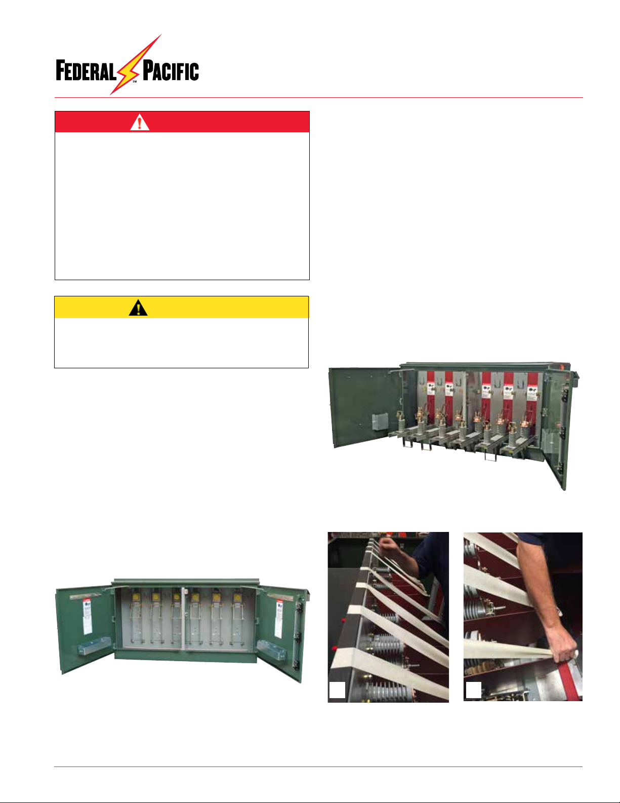
RE-INSTALLATION OF SWITCH BARRIERS IN TYPE PSE
DEAD-FRONT PAD-MOUNTED SWITCHGEAR
NOVEMBER 2017
Page 1
© 2015 Electro-Mechanical Corporation
RE-INSTALLATION OF SWITCH BARRIERS IN TYPE
PSE DEAD-FRONT PAD-MOUNTED SWITCHGEAR
NOTE: These are general operational procedures for
re-installation of switch barriers in dead-front (PSE)
pad-mounted switchgear from Federal Pacific.
Consult the factory for specific information, such as
the length of gasket material needed and any other
specific issues. The factory will require the serial
number of the switchgear unit in order to provide this
information.
If you do not understand any portion of this instruction
bulletin and need assistance, contact Federal Pacific
at 276-669-4084.
This document contains proprietary information of Electro-Mechanical Corporation or its operating divisions in whom title remains. Any repro-
duction, distribution, disclosure or use not otherwise expressly approved in writing is strictly prohibited. Designated trademarks and brands are
the property of their respective owners.
INSPECTION & MAINTENANCE RECOMMENDATIONS
Qualified Persons
The equipment covered by this publication must be selected for
a specific application and it must be operated and maintained by
QualifiedPersonswhoarethoroughlytrained andknowledgeable
in the installation, operation, and maintenance of underground
power distribution equipment along with the associated hazards
that may be involved. This publication is written only for such
qualified persons and is not intended to be a substitute for
adequate training and experience in safety procedures for this
type of equipment. Proper installation is the responsibility of the
operating and construction personnel and the utility performing
and authorizing the work. Completion of these instructions implies
no further warranty by the manufacturer.
A Qualified Person is defined in the National Electrical Code
(NEC/NFPA-70) as:
One who has skills and knowledge related to the construction
and operation of the electrical equipment and installations and
has received safety training to recognize and avoid the hazards
involved.
The specific electrical safety training requirements to be
considered a qualified person are detailed in NFPA-70E, Article
110.1(D), Employee Training. Some of the requirements from the
2012 edition are shown in the adjacent column. For the specific
detailedtrainingrequirementsfora Qualified Person make certain
to refer to the most recent applicable edition.
These training requirements would include, but are not limited,
to the following key points:
• The skills and techniques necessary to distinguish exposed
energized parts from other parts of electrical equipment.
• The skills and techniques necessary to determine the proper
approach distances corresponding to the voltages to which the
qualified person will be exposed.
• Theproperuseofthespecialprecautionarytechniques,personal
protective equipment, insulating and shielding materials, and
insulated tools for working on or near exposed energized parts
of electrical equipment.
• Tasks performed less often than once per year have additional
training requirements.
These instructions are intended only for such qualified persons.
They are not intended to be a substitute for adequate training
and experience in safety procedures for this type of equipment.
Additionally, the recommendations in this instruction bulletin are
not intended to supersede or to take the place of established
utility safety guidelines and established practices. If there is any
question, consult with your foreman or supervisor, as appropriate.
Please refer to OSHA 29 CFR 1910.399 and NFPA 70E Articles 100
and 110.
WARNING