5
Installation and Maintenance Manual
Model 300MB-SD CommCenter Series D1
Safety Message to Installers of Federal Signal Products
People’s lives depend on your proper installation and servicing of Federal Signal products. It is important to
read and follow all instructions shipped with this product. In addition, listed below are some other important
safety instructions and precautions you should follow:
• This device is to be installed by a trained electrician who is thoroughly familiar with the National
Electric Code and will follow the NEC guidelines as well as local codes.
• The selection of the mounting location for the device, its controls and routing of the wiring is to be
accomplished under the direction of the Facilities Engineer and the Safety Engineer.
• Read and understand all instructions before installing or operating this equipment.
• Do not connect this unit to the system when power is on.
• Optimum sound distribution will be severely reduced if any objects are in front of the speaker. You
should ensure that the front of the speaker is clear of any obstructions.
• All effective warning speakers produce loud sounds which may cause, in certain situations, permanent
hearing loss. You should take appropriate precautions such as wearing hearing protection.
• All effective warning speakers produce loud sounds, which may cause, in certain situations, permanent
hearing loss. The device should be installed far enough away from potential listeners to limit their
exposure while still maintaining its effectiveness. The OSHA Code of Federal Regulations 1910.95
Noise Standard provides guidelines, which may be used regarding permissible noise exposure levels.
• After installation, test the sound system to ensure proper operation.
• Show these instructions to your Safety Engineer and all operating personnel, and then file them in a safe
place and refer to them when maintaining and/or reinstalling the unit.
• Establish a procedure to routinely check the sound system for proper activation and operation.
Failure to follow all safety precautions and instructions may result in property damage, serious injury, or death.
Unpacking the Product
After unpacking the product, examine it for damage that may have occurred in transit. If the 300MB has been
damaged, do not attempt to install or operate it. File a claim immediately with the carrier, stating the extent of the
damage. Carefully check all envelopes, shipping labels, and tags before removing or discarding them. Disposal of
all shipping materials must be carried out in accordance with national and local codes and standards. If any parts
are missing, please call Federal Signal Customer Support at 708-534-4756 or 877-289-3246.
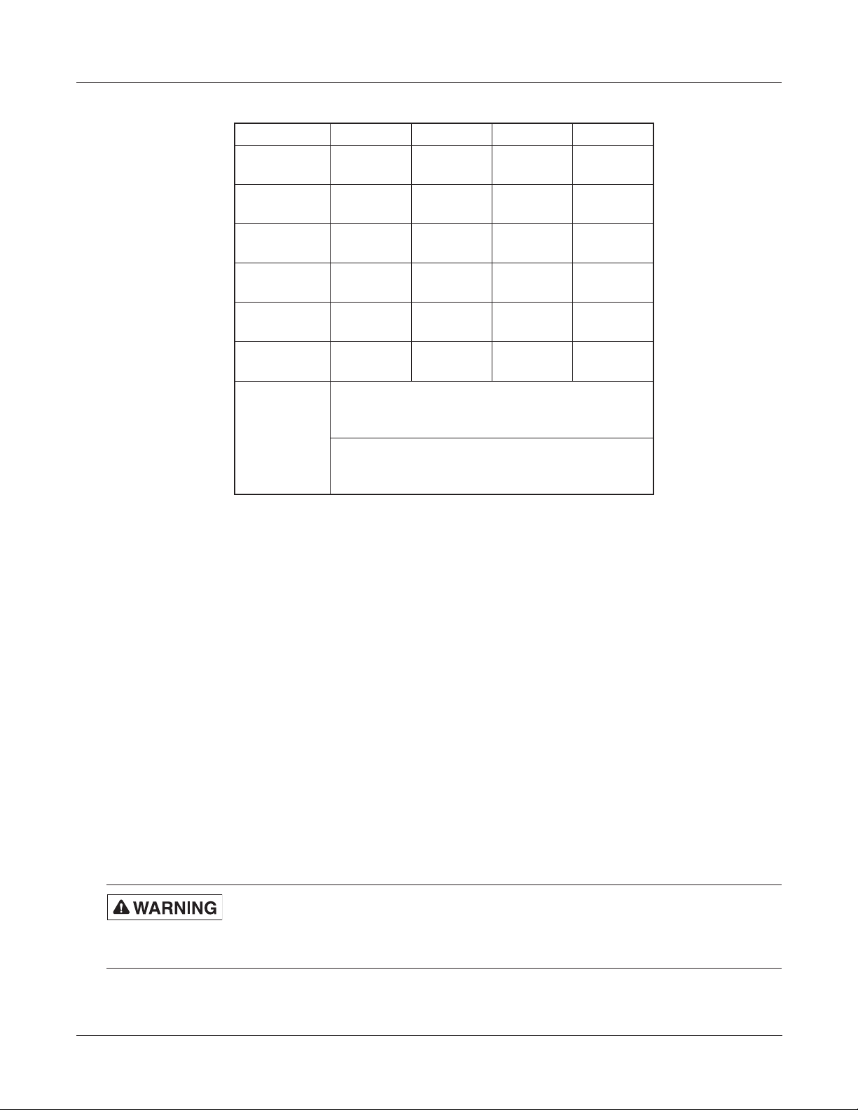
Table 1 Kit contents
Qty. Description Part Number
1 Plug, 10-Position 140332-10
1 Plug, 17-Position 140332-17