Federal Signal Corporation FT200C-V User manual

Limited Warranty: This product’s limited warranty can be
found at www.fedsig.com/SSG-Warranty.
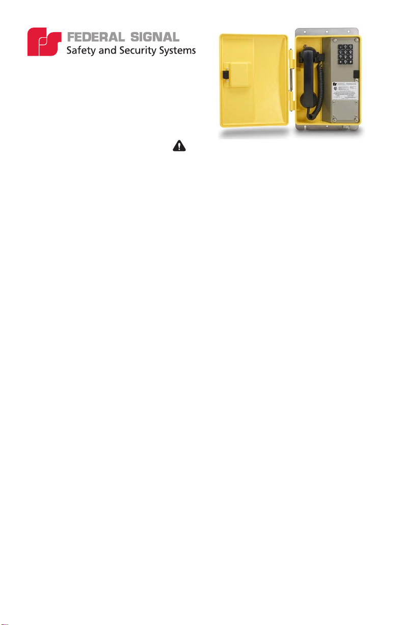
FT200C-V
Weather Resistant VoIP Hazardous Location
Telephone
25500869 Rev A0 1123
SAFETY MESSAGES TO INSTALLERS AND USERS :
The equipment is not intended for repair by the user. Repair of this equipment shall be carried out by the manufacturer
or manufacturer’s authorised agent.
It is the responsibility of the end user to take suitable precautions to prevent exposure to aggressive chemicals that
may attack metals or the polymeric materials used in the construction of this equipment. Specic details of vulnerable
materials shall be provided in the instructions.
• Read and understand instructions before installing or operating equipment.
• Do not install this device near any heat sources such as radiators, heat registers, stoves, or other apparatus
(including ampliers) that produce heat.
• Only use attachments and accessories specied by the manufacturer.
• Refer all servicing to qualied service personnel.
• Prior to installation, consult local building and electrical code requirements.
• WARNING: ELECTRICAL HAZARD — This product should be installed by a licensed electrician according to all
electrical and building codes.
• WARNING: HAZARDOUS AREA — Before opening the enclosure, ensure that the area is safe and that the power
conductors are not live. When replacing the faceplate, ensure that the wires or other foreign objects are not trapped
between the edges. Anything the prevents the base and the faceplate from being in direct contact nullies the
hazardous area rating of the telephone.
• WARNING: DISLOCATION HAZARD — To prevent injury, this apparatus must be securely attached to the oor or
wall in accordance with the installation instructions.
• Suitable for use in class i, division 2, groups a, b, c and d hazardous locations or nonhazardous locations only.
• WARNING: EXPLOSION HAZARD — Do not disconnect equipment while the circuit is live or unless the area is
known to be free of ignitable concentrations.
• WARNING: EXPLOSION HAZARD — Substitution of components may impair suitability for class I, division 2
hazardous locations.
• WARNING: CHEMICAL HAZARD — Exposure to some chemicals may degrade the sealing properties of materials
used in the sealed relay device.
Failure to follow all safety precautions and instructions may result in property damage, serious injury, or death to you or
others.

2Federal Signal signaling.fedsig.com
Table 1 Specications
Electrical Performance
Ringer Output >80 dB
Microphone Noise reducing electret
Receiver Hearing aid compatible
Category
Ethernet I/F 10/100 MBPS
Protocol SIP RFC 3261 compatible
Power Input
- Method #1
- Method #2
802.3 AF compliant PoE switch or power injector
24 Vdc at 1A power adapter
CODECS Supported G711, A-LAW AND µ-LAW
G722.1 (SIREN7)
G722.2 (AMR-WB)
G729.1 (G729J AND G729EV)
Relay Contact Fuse protected to 1 A at 30 Vdc
Environmental
Weather and Corrosion Resistant Enclosure NEMA 3R
Temperature -22° to +140°F (-30° to +60°C)
Humidity 0 to 100% RH
Mechanical
Hook Switch (Cradle Switch) Life >1,000,000 Operations
Body Construction GE VALOX™357 engineering polymer
Faceplate Steel, corrosion protected and powder coated
Dimensions (H X W X D) 12 X 9.6 X 3.9 inches (305 x 245 x 99 mm)
Net Weight Including Mounting Plate 7 lb (3.2 kg)
Shipping Dimensions 15 X 11.5 X 5 inches (381 x 293 x 127 mm)
Shipping Weight Including Mounting Plate 8 lb (3.7 kg)
Handset Material High impact ABS
Standard Mounting Vertical wall
Wiring Access 1/2"NPT Conduit Hub
Hardware Material Stainless steel
Table 2 A-Compliance
UL/CUL Class I, Division 2, Groups A,B,C and D
FCC Part 15, Class A
IC ICES-003 Class A
CISPR 22: 2008
IEC 61000-6-2: 2005
0518
Weatherproof Enclosure Type 3R
This device complies with part 15 of the FCC Rules. Operation is subject to the following two conditions: (1) This device
may not cause harmful interference, and (2) this device must accept any interference received, including interference
that may cause undesired operation.

3
Federal Signal signaling.fedsig.com
GENERAL: The Federal Signal FT200C-V weatherproof, hazardous location telephone is designed to provide safe, reliable
communication in areas prone to high humidity, chemical vapors, dust, and physical abuse. The telephone is compatible
with most SIP-based IP PBX servers that comply with SIP RFC 3261. Users can remotely monitor and program settings
through a web browser to congure the telephone on their network.
Features
• Enclosure
• VALOX™body construction
• Weather and corrosion resistant
• Spring-loaded hinged door
• Temperature range -22˚ to +140˚F ( -30˚ to +60˚C)
• 12-key teleseal keypad
• Waterproof connections and stainless steel ttings for longer life
• Corrosion protected and powder coated steel faceplate
• Magnetic reed hook switch — no moving parts
• Easily mounted on any sturdy, vertical structure
• Noise reducing microphone allows a high level of intelligibility in locations with high background noise
• Heavy duty G-type industrial handset
• Handset retainers to maintain on-hook status
• Modular parts for easy service
• Hearing Aid Compatible and Receiver Volume Adjustment
• Compatible with inductively coupled hearing aid devices
• Adaptive full duplex operation
• Compatible with most SIP-based IP PBX servers that comply with SIP (RFC 3261)
• Network web management interface
• The discovery utility makes it easy to detect, locate, and launch the web-based conguration screens
• Product self-diagnostic testing available through the web interface
• Network-adjustable speaker volume and microphone sensitivity sets the default levels. User-adjustable volume
control on the handset
• PoE 802.3af enabled (Power-over-Ethernet) or alternate power source
• Web-based user interface allows remote setup of network, product operations, updates, self-diagnostics, and other
functional access
• Dual speeds of 10 Mbps and 100 Mbps
• Network/Web management
• Dial Out Extension supports the addition of comma delimited pauses before sending additional DTMF tones
• Network downloadable product rmware
• Tamper proof design
• Autoprovisioning and Device Conguration Export/Import saves setup time on multiple deployments
• Congurable audio les
• Event Monitoring / Triggers (Refer to VoIP Conguration Guide – Part Number 25500857)
• Peer-to-peer capable

4Federal Signal signaling.fedsig.com
Supported Protocols
The FT200C-V Telephone with Keypad supports:
• SIP (Session Initiation Protocol)
• HTTP Web-based conguration
• Provides an intuitive user interface for easy system conguration and verication of FT200C-V Telephone with
Keypad operations.
• DHCP Client
• Dynamically assigns IP addresses in addition to the option to use static addressing.
• TFTP Client
• Facilitates hosting for the autoprovisioning conguration le.
• RTP
• Facilitates autoprovisioning conguration values on boot.
• Audio Encodings
• PCMU (G.711 mu-law)
• PCMA (G.711 A-law)
• G722.1 (Siren7)
• G722.2 (AMR-WB)
• G729.1 (G729J & G729EV)
Supported SIP Servers
As a SIP device, this product will operate with most IP PBX servers.
Installation
The Voice-over-IP (VoIP) FT200C-V Telephone is a Power-over-Ethernet (PoE 802.3af) and Voice-over-IP (VoIP) two-way
communications device that easily connects into existing local area networks (LANs) with a single cable connection.
Figure 1 illustrates how the FT200C-V Telephone can be installed as part of a VoIP phone system.
Figure 1 Typical VoIP Installation

5
Federal Signal signaling.fedsig.com
Figure 2 Features
Figure 3 Dimensions
SHOCK HAZARD: If using an auxiliary power supply, ensure that it is unplugged during installation to avoid an
accidental shock or circuit damage.
NOTES:
• Follow all appropriate electrical codes and use only approved electrical ttings for the installation
• Determine if power to operate the telephone will be provided via the Ethernet or if external power will be required. If
external power is required, install auxiliary power supply.
• To maintain Ingress Protection / NEMA ratings, use appropriately rated hardware and waterproong techniques.

6Federal Signal signaling.fedsig.com
• Choose a wall location that is free of obstructions and permits space for conduit runs.
• Ensure that mounting can support 7 lb (3.2 kg) and any additional foreseeable load.
To install the telephone:
1. Separate the faceplate from the housing.
2. Use the template provided or the enclosure itself to locate and drill holes for mounting screws.
3. Secure the unit to the wall with user-supplied 1/4"or M8 screws.
4. Bring the Network cable into the enclosure through the conduit entrance and plug into the RJ-45 connector on the
PCBA. See Figure 4.
Figure 4 Wiring
Figure 5 Circuit Board

7
Federal Signal signaling.fedsig.com
5. If using an alternate power supply, connect the supply to the terminal block J9. Before doing so, determine if
power is supplied over the Ethernet cable.
6. Connect the on-board relay if utilized.
7. Reconnect the faceplate harness.
8. Ensure that all connections are secure.
9. Verify that the telephone is properly connected by pressing the RESET switch for less than ve seconds to
announce the IP address. LEDs on the RJ45 connector indicate network connection and activity.
10. Replace the faceplate.
11. Set up and congure the telephone if changes are required to the default settings.
12. Call to and from another telephone, preferably a VoIP device, to test the unit.
Operation
The FT200C-V telephone may be set up for either keypad dialing or auto-dialing.
If the telephone is congured for keypad, dialing operation is identical to most other single-line telephones.
If the telephone is congured for auto dialing, lift the handset and press the number assigned to the extension to be
dialed.
The telephone dials the programmed number when the handset is lifted.
Adjust the receiver volume with the switch in the handset.
Setup
Connections
Figure 6 shows the pin connections on the J9 (terminal block). This terminal block can accept a wire range from 16 AWG
to 26 AWG.
NOTE: As an alternative to using PoE power, 24 V at 1 A can be supplied to the terminal block.
Figure 6 Terminal Block Connections

8Federal Signal signaling.fedsig.com
Connecting a Device to an Auxiliary Relay
The FT200C-VoIP Telephone incorporates a one on-board relay located on the PCBA, which enables users to control a
low current external relay or device. An external relay can control a ringer, strobe light, door lock, or any other apparatus.
The on-board relay is protected by a 1 A, non-replaceable fuse. Power switched by the relay should not exceed the rating
of the fuse. Consideration of a safety factor is recommended.
The relay circuitry contains a non-replaceable 250 Vac 1 A fuse. If the fuse blows, the board must be returned to
Federal Signal or an approved service center for repair.
The telephone relay activation time is selectable through the web interface on the Device Conguration Page. The relay
can be controlled by DTMF tones generated from the monitoring phone to which the VoIP phone is connected or by other
methods. Refer to VoIP Conguration Guide – Part Number 25500857.
NOTES:
• The three-digit code for the auxiliary relay must be sent in conformance with RFC2833 DTMF generation.
• Firmware version 3.4.0 or later requires a “#” to execute the DTMF command.
Example: 321# - activate relay.
See Figure 7 and Table 3 to identify the connector locations and functions.
Figure 7 Connector Locations
Table 3 Connector Functions
Connector Function
J1 PoE Network Connection (RJ-45)
J2 Hands free Microphone Interface/LED Interface
J3 Not used
J4 JTAG Interface
J5 Handset/Reed Switch Interface
J6 Speaker Interface
J7 Keypad Interface
J8 RS232 Port
J9 Terminal Block (see Figure 5)
J10 Not used
J11 Handset V.C. Interface
J12 ISP-DIP/Debug UART

9
Federal Signal signaling.fedsig.com
Network Connectivity and Data Rate
When you plug in the Ethernet cable or power supply, the square, green Link light above the Ethernet port indicates that
the network connection has been established. (See Figure 8.) The Link light changes color to conrm the auto-negotiated
baud rate:
• This light is yellow at 10 Mbps.
• It is orange at 100 Mbps.
Verify Network Activity
The square, yellow Activity light blinks when there is network activity.
Figure 8 Network Activity
Reset Switch
When the telephone is operational and linked to the network, use the Reset Test Function Management (RESET) switch
(Figure 9) on the Telephone board to announce the Telephone’s IP Address, and verify that the audio is working. The
message comes through the handset receiver.
Figure 9 RESET Switch

10 Federal Signal signaling.fedsig.com
Announcing the IP Address
To announce a telephone’s current IP address:
1. Press and release the RESET switch (SW1). Do not hold more than ve seconds.
2. The telephone announces that it is restoring the factory default settings.
NOTE: The telephone uses DHCP to obtain the new IP address (DHCP-assigned address or default to 10.10.10.10 if a
DHCP server is not present).
Restore the Factory Default Settings
When troubleshooting conguration problems, it is sometimes convenient to restore the device to a known state.
NOTE: Each telephone is delivered with factory set default values.
To set the factory default settings:
1. Press and hold the RESET switch (SW1) for more than ve seconds.
2. The telephone announces that it is restoring the factory default settings.
The telephone uses DHCP to obtain the new IP address (DHCP-assigned address or default to 10.10.10.10 if a DHCP
server is not present).
Adjust the Volume
You can adjust the volume through the Device Conguration Page.
Field Repairs
Field repairs must be carried out only by qualied technicians using OEM parts. Substitution of parts voids the warranty
and may pose a hazard to users of the equipment.
To make repairs to the telephone:
1. Disconnect the telephone IP Cable and Aux Power if necessary.
2. Carefully remove the front cover assembly and separate it from the housing by disconnecting the harness plugs.
Note that the handset and all electronics are attached to the front plate.
3. Perform the necessary repairs or adjustments.
4. Carefully replace the front plate and install all the screws. Do not overtighten the cover screws. There is a exible
gasket between the cover and the body; excessive tightening of the screws deforms the gasket and reduces the
weather resistance of the set.
Handset Replacement
Refer to the instruction sheet included with the replacement handset.
To replace the handset:
1. Disconnect the handset wiring from the PCBA.
2. If the phone is equipped with an armored cord handset, remove the anchor screw from the armored cord lanyard.
3. Loosen the handset cable gland and pull out the cord.
4. Install the new replacement handset and tighten the gland.
5. Rewire the handset cord to the PCBA.

11
Federal Signal signaling.fedsig.com
Ringer Replacement
To replace a ringer:
1. Disconnect the ringer wiring from the terminal block on the PCBA.
2. Remove the screws that hold the ringer to the housing.
3. Install the new ringer and gasket.
4. Reconnect the ringer wiring to the terminal block.
Main Circuit Board Replacement
To replace the circuit board:
1. Label any wiring attached to the circuit board. Disconnect the wiring and ribbon cable.
2. Remove the two screws holding the circuit board in place. Carefully remove the board.
3. Install the new board and reconnect the wiring.
4. If the conguration had been changed from the factory default settings, reprogram the telephone.
5. Make and receive calls from another telephone to test it.
Cleaning the Telephone
The telephone may occasionally need to be cleaned to maintain its appearance. Generally, wiping the surface with a
clean, water-dampened cloth will remove most lms or residues. If the soiling is too stubborn for plain water, a mild
detergent solution may be used. Wipe away any detergent residue with a plain water dampened cloth. The telephone
may be cleaned with any general-purpose household glass and surface type cleaner. Do not spray the telephone
directly! Spray the cleaner on a soft cloth and then wipe the surface. Pretreated cloths, like those used for eyeglasses
or cameras, may be used to clean the telephone. Pre-moistened towelettes may also be used; however, avoid those
containing lanolin or aloe, as they will leave a slippery residue. The handset and surface of the telephone may be
cleaned with disinfectants used for general cleaning in a medical environment. Isopropyl alcohol may be used applied
with a cloth. Avoid using alcohol on silicon-based keypads, since doing so may signicantly degrade legibility.
• Do not use furniture polishes, waxes, or plasticizer-based cleaner
• Do not use lanolin, aloe, glycerin, or other skin care type products.
• Do not apply any solvent such as acetone, mineral spirits etc.
• Do not directly spray or immerse the handset.
Storage
General Storage (All situations):
• Note any stacking limits or warnings on the packaging (if any).
• Do not store in temperatures over +80C.
• Store the unit in original packaging if possible until it is needed.
Long Term Storage (> 6 Months):
• If the area is air conditioned and not subject to high changes in humidity, continue to store the unit in its original
packaging.
• If wide humidity shifts are expected, then follow these steps:
• Remove the product from its packaging (including plastic bags) and store it on a shelf in open air.
• If the area is subject to a high degree of dust, to help maintain the cosmetic appearance, you can cover it with
a cloth (do not cover the unit with plastic or materials that will trap moisture) or clean periodically.
• Do not store the unit out of its packaging long term where it would be are exposed to sunlight. Long-term
exposure to UV may cause fading.

2645 Federal Signal Drive, University Park, Illinois 60484
Additional translations available at signaling.fedsig.com
Traducciones adicionales disponibles en signaling.fedsig.com
signaling.fedsig.com
Maintenance and Service
Repair Service: A return authorization is required. Contact your Authorized Distributor or Federal Signal Customer
Support. Defective products under warranty will be repaired or replaced at Federal Signal’s discretion.
Product Returns: Returns require authorization from Federal Signal. Contact your Authorized Distributor for more
information on our return policy or to request a return.
Ordering Replacement Parts
Consult the product datasheet online for an updated list of replacement parts. If the product requires a part that is not
available for purchase, your unit must be repaired or replaced.
Table 4 Replacement parts
Description Part Number
Handset 4' Curly Cord C/W VC, Tx and Rx P007228
PCBA- VoIP P007395
Table of contents
Other Federal Signal Corporation IP Phone manuals