Federal LPRSS-2 Installation instructions

- 1 -
E2915-2
Revised 1/11/2012 ECN2000
INSTALLATION & OPERATIONS INSTRUCTIONS
REFRIGERATED LPRSS-2 MODELS
KEEP THIS MANUAL FOR FUTURE REFERENCE
Engineering and technical data are subject to change without notice.
FEDERAL INDUSTRIES 215 FEDERAL AVE Belleville, WI 53508
Toll Free 1(800) 356-4206 WI Phone (608) 424-3331 Fax: (608) 424-3234

- 2 -
CONTENTS
INTRODUCTION.......................................................................................................................................3
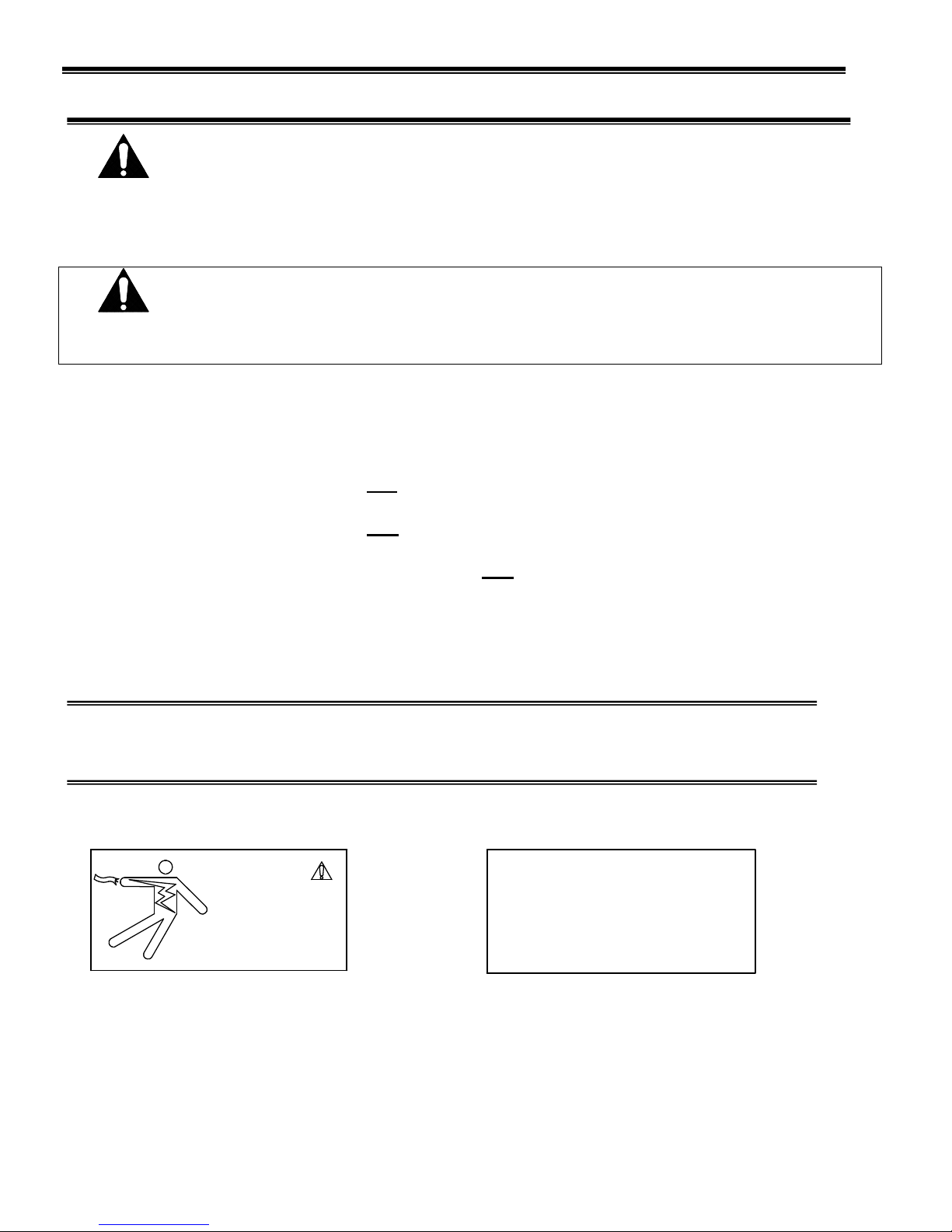
WARNING LABELS & SAFETY INSTRUCTIONS..............................................................................4
PRE-INSTALLATION PROCEDURES...................................................................................................5
Inspection For Shipping Damage.....................................................................................................5
GENERAL ELECTRICAL & GROUNDING.........................................................................................5
Cord Connected................................................................................................................................5
Permanent Connected (Option)........................................................................................................5
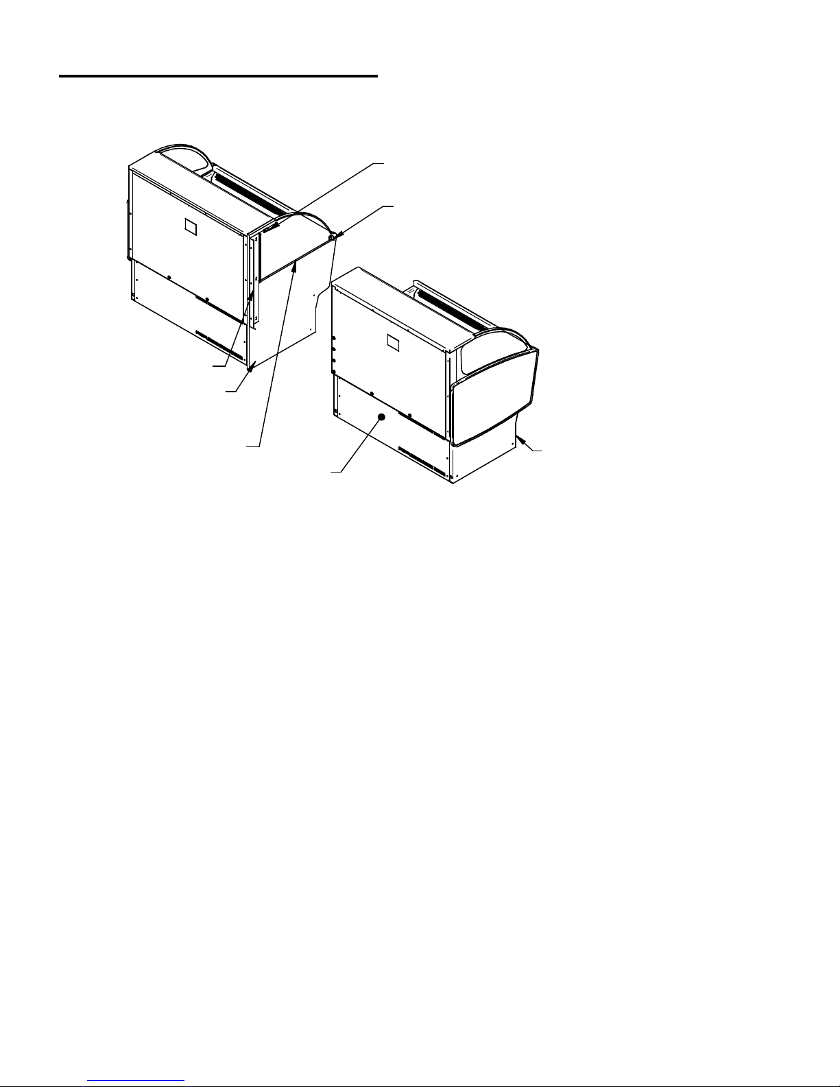
INSTALLATION INSTRUCTIONS..................................................................................................... 6-8
Locating The Display Case ..............................................................................................................6
Removing Case From Shipping Skid...............................................................................................6
Cleaning ...........................................................................................................................................6
Center Panel Joining (Option)..........................................................................................................7
Refrigeration System........................................................................................................................8
Self Contained Models................................................................................................................8
Remote Models............................................................................................................................8
Evaporator Condensate Drain Tube .................................................................................................8
Condensate Pump.............................................................................................................................9
SHELVING INSTALLATION & REMOVAL................................................................................ 10-12
Metal Shelves.................................................................................................................................10
Glass Shelves..................................................................................................................................11
Optional Shelf Lights (Option).......................................................................................................12
PLASTIC END REMOVAL & INSTALLATION ...............................................................................13
REAR DOORS (OPTION).......................................................................................................................12
NIGHT CURTAIN (OPTION).................................................................................................................14
SECURITY NIGHT COVER (OPTION)...............................................................................................15
OPERATING INSTRUCTIONS .............................................................................................................16
User Controls..................................................................................................................................16
Temperature Control Function........................................................................................................17
Initial Start Up................................................................................................................................17
Placing Product In Case .................................................................................................................18
MAINTENANCE ......................................................................................................................................19
Light Replacement .........................................................................................................................19
PERIODIC MAINTENANCE .................................................................................................................19
Cleaning Condenser Coil................................................................................................................19
CLEANING INSTRUCTIONS.......................................................................................................... 20-21
Daily Cleaning................................................................................................................................20
Weekly Cleaning...................................................................................................................... 20-21
SALE & DISPOSAL.................................................................................................................................22
Owner Responsibility.....................................................................................................................22
SERVICE INFORMATION ....................................................................................................................22
Pre-Service Checklist.....................................................................................................................23
Special Service Situations..............................................................................................................23
Refrigeration & Electrical Data.......................................................................................................24
Electronic Control Operation ..........................................................................................................24
Control Factory Settings..................................................................................................................25
Control Display ...............................................................................................................................25
Refrigeration Operation...................................................................................................................26
Self Contained Models..............................................................................................................26
Remote Models.................................................................................................................... 26-27
WIRING DIAGRAMS..............................................................................................................................28
Self Contained................................................................................................................................28
Remote ...........................................................................................................................................28
REPLACEMENT PARTS.................................................................................................................. 29-30

- 3 -
INTRODUCTION
Thank you for purchasing a Federal Industries display case. This manual contains important instructions for
installing and servicing the LPRSS Refrigerated Self-Service Merchandisers. A repair parts list and wiring
diagram are also included in the manual. Read all of these documents carefully before installing or servicing
your case.
NOTICE
Read this manual before installing your case. Keep this manual and refer to it before doing any
service on the equipment. Failure to do so could result in personal injury or damage to the case.
NOTICE
Installation and service of the electrical components in the case must be performed by a licensed
electrician.
The portions of this manual covering components contain technical instructions intended only for persons
qualified to perform electrical work.
DANGER
Improper or faulty hookup of electrical components in the case can result in severe injury or death.
All electrical wiring hookups must be done in accordance with all applicable local, regional, or
national standards.
SERIAL NUMBER
Record the model and serial numbers of the case for easy reference. Always refer to both model and serial
numbers in your correspondence regarding the case.
Case Model__________________________ Serial Number______________________
Condensing Unit Model________________ Serial Number______________________
This manual cannot cover every installation, use, or service situation. If you need additional information,
call or write us: WARRANTY/TECHNICAL SERVICE DEPARTMENT
Federal Industries
P.O. Box 290
Belleville, WI 53508
Toll Free (800) 356-4206 / WI Phone (608) 424-3331

- 4 -
WARNING LABELS & SAFETY INSTRUCTIONS
This is the safety-alert symbol. When you see this symbol on your case or in the
manual, be alert to the potential for personal injury or damage to your equipment.
Be sure you understand all safety messages and always follow recommended precautions and safe
operating procedures.
NOTICE TO EMPLOYERS
You must make sure that everyone who installs, uses, or services your case is thoroughly
familiar with all safety information and procedures.
Important safety information is presented in this section and throughout the manual. The
Following signal words are used in the warning and safety messages:
DANGER: Severe injury or death will occur if you ignore the message.
WARNING: Severe injury or death can occur if you ignore the message.
CAUTION: Minor injury or damage to your case can occur if you ignore the message.
NOTICE: This is important installation, operation, or service information. If you ignore the
message, you may damage your case.
The warning and safety labels shown throughout this manual are placed on your Federal
Industries case at the factory. Follow all warning label instructions. If any warning or safety labels
become lost or damaged, call our customer service department at 1(800) 356-4206 for replacements.
This label is located on the back of the display case. This label is located below the display pan.
CAUTION
POWER BEFORE
RISK OF ELECTRIC
SHOCK DISCONNECT
91-12340
SERVICING UNIT.
CAUTION
HAZARDOUS MOVING PARTS
DO NOT OPERATE UNIT WITH
DISPLAY PANS REMOVED.

- 5 -
PRE-INSTALLATION PROCEDURES
Inspection for Shipping Damage
You are responsible for filing all freight claims with the delivering truck line. Inspect all cartons
and crates for damage as soon as they arrive. If damage is noted to shipping crates, cartons, or if a
shortage is found, note this on the bill of lading (all copies) prior to signing.
If damage is discovered when the case is uncrated, immediately call the delivering truck line and
follow up the call with a written report indicating concealed damage to your shipment. Ask for an
immediate inspection of your concealed damage item. Crating material must be retained to show
the inspector from the truck line.
GENERAL ELECTRICAL & GROUNDING
DANGER: Improper or faulty hookup of electrical components in the
display case can result in severe injury or death.
Cord Connected
-All standard models are supplied with a power cord that is properly sized to the amperage requirements of
the case. See the electrical data plate located on the rear left interior of the case for the proper circuit size
for each case.
- The cord is factory installed protruding from the bottom rear corner of the case.
-A separate circuit for each display case is required to prevent other appliances on the same circuit from
overloading the circuit and causing malfunction.
Permanent Connected (OPTION)
-Only a licensed electrician must perform all case electrical connections.
-All electrical wiring hookups must be done in accordance with all applicable local, regional, or national
electrical standards.
-A separate circuit for each display case is required to prevent other appliances on the same circuit from
overloading the circuit and causing malfunction.
-The electrical service must be grounded upon installation.
-See the electrical data plate located at the rear of the case for proper circuit size and wire ampacity.
-The electrical connection box is accessible from the rear of the case with rear grill removed.
FIELD CONNECTION BOX
POWER CORD OR
CONDUIT CONNECTION
HOLE (7/8"O)
REAR BASE
PANEL
(6) REAR BASE
PANEL SCREWS

- 6 -
INSTALLATION INSTRUCTIONS
Locating Display Case
The case should be located where it is not subjected to the direct rays of the sun, heating ducts, grills,
radiator, or ceiling fans, nor should it be located near open doors or main door entrances. Also, avoid
locations where there are excessive air movement or air disturbances.
The case requires a minimum of 6” clearance at the rear of the unit for air discharge. Do not locate case
with back tight against the wall. The louvers located on front of base must remain clear for air intake. If
rear clearance or front clearance is not possible see a Federal representative for air intake and discharge kit
options.
No clearance is needed on sides of the unit.
Removing Case From Shipping Skid and General Installation
CAUTION: Do not push or pull against the top panel, plastic end, end glass, or
door frames when removing the case from the skid or moving the case. Case
damage or glass breakage could result.
1. Remove crate top and sides and note missing or damaged items as explained in the pre-installation
procedures outlined above.
2. Move the case as near as possible to the final location and before removing it from the shipping skid.
3. Remove the (4) brackets that secure the case to the shipping skid.
4. Prepare cabinet according to instructions in this section that pertain to your model.
5. Lift the case off of skid and into required position. Only lift the case from under the rear lip and front
bottom trim channel above the base. Note: Do not push or pull on front bottom trim channel or lift
using the plastic end panel.
6. The case must be level for proper drainage of defrost condensate to the condensate evaporator. Using
the wrench provided level and square the case as needed by adjusting the leg leveler in each corner of
base. The 6’cases also have a set of leg levelers in the center. These must be adjusted so the base is flat.
7. The leveled case must be sealed to the floor using a NSF Listed Sealant.
Cleaning
For initial setup, clean the case as outlined in the “Weekly Cleaning” section of this manual.

- 7 -
Center Panel Joining (Option)
If your cases where ordered with the Center Panel Joining Option you will need to perform the following
installation procedures.
FRONT JOINING
BRACKET
REAR JOINING TRIM
CENTER PANEL
BASE MOUNTING
HOLES (4)
RIGHT CASE
LEFT CASE
LEFT CASE REAR
BASE PANEL
LEFT CASE FRONT
BASE PANEL
TOP JOINING
BRACKET
INTERIOR JOINING FLANGE
1. Place the right case into desired location and level case by adjusting leg levelers with provided
wrench.
2. Remove the front base panel (4) screws and rear base panels (6) screws from the left case. Push
the left case end tightly against the right case end. The rear joining trim on the right case must
be behind the back panel of the left case and the front joining bracket on the right case must be
inside the front aluminum trim channel of the left case.
3. Adjust the leg levelers on the left case so it is level and exactly aligned with the right case. The
(4) base mounting hole in the right case panel must align with the (4) mounting holes located in
base compartment of left case.
4. Push the cases together as tightly as possible and the gap between the cases must be tight and
even. If the gap is larger at the top or the bottom adjust leg levelers accordingly. HOLD CASES
TOGETHER AS TIGHT AS POSSIBLE WHILE ATTACHING ALL JOINING BRACKETS
AND DO NOT OVER TIGHTEN SCREWS OR SCREWS WILL STRIP OUT.
5. Attach the bottom of the left case to the right case center panel base mounting holes through the
holes located inside of the left case base. Use the (4) large 10-12x1/2 screws provided.
6. Attach the rear top of left case through the holes in the rear joining bracket using the (3) black
#10-12x1/2 self drilling screws provided.
7. Attach the front of left case through the holes in the front joining bracket using the (2) smaller
#8-12x1/2 self drilling screws provided.
8. Attach the top of left case through the holes in the top joining bracket using the (2) smaller
#8-12x1/2 self drilling screws provided.
9. Attach the interior of left case through the holes in the interior joining flange using the (3)
smaller #8-12x1/2 self drilling screws provided
10. If any there are any gaps along the joining seam fill them with NSF black silicone.
11. Reinstall front and rear grills.

- 8 -
Refrigeration System:
Self Contained Models
The self-contained models are shipped from the factory with a completely operational 404A refrigeration
system and require no modifications or adjustments upon installation. Case must be installed as per the
installation section of this manual to provide proper condensing air cooling.
Remote Models
The remote models are designed to use 404A refrigerant and shipped from the factory with the evaporator
coil, expansion valve, sight glass, service valves and refrigerant solenoid valve. Installation must be
performed by a licensed Refrigeration Technician. See the Service section of this manual for installation
requirements.
Evaporater Condensate Drain Tube:
WARNING TO INSTALLER
Evaporator Condensate Drain Tube may become dislodged during shipping. Installer must
check Evaporator Condensate Drain Tube upon installation to be sure drain tube is
properly seated and installed correctly.
Evaporator Drain Tube must be attached to tube protruding from bottom of Evaporator Tub and must either
be inside the Condensate Pan area or inside of hole of Condensate Pump.
E APORATOR
CONDENSATE
DRAIN TUBE
E APORATOR
CONDENSATE
DRAIN TUBE
CONDENSATE PAN CONDENSATE PUMP

- 9 -
Condensate Pump:
A condensate pump is Standard on some models and Optional on all models. Installer must check unit to
see if a condensate pump has been provided with case.
WARNING TO INSTALLER
Installer must determine if case was provided with condensate pump. Failure to hook up
pump hose to drain will cause water on floor and cause a slip hazard.
CONDENSATE PUMP
DRAIN TUBE
CONDENSATE PUMP
CONDENSATE
DRAIN TUBE
DRAIN TUBE
EXIT LOCATIONS
DRAIN TUBE
EXIT LOCATIONS
DRAIN TUBE
EXIT LOCATIONS
DRAIN TUBE
EXIT LOCATIONS
Instead of using heat energy to remove condensate run off from evaporator coil a condensate pump pumps
the water to a nearby drain.
-The Condensate Pump is provided with 50’ of clear 1/2 OD x 3/8 ID tubing that must be run out of base
area to a drain.
-There are several Drain Tube exit locations provided in base as noted in drawing above. Plugs or caps will
need to be removed in desired exit location.
-Hose can be run entire 50’ in any direction as required, but no higher than 20’ from pump base. A check
valve is provided in pump to prevent water from flowing back into reservoir. For best efficiency extend
hose level below or level of pump base to create a siphoning effect. Never run hose to or through an area
below freezing or freezing water will block tube.

- 10
-
SHELVING INSTALLATION & REMOVAL
Metal Shelves Installation
SHORTER TOP SHELF
LONGER BOTTOM SHELF
SHORTER TOP SHELF BRACKET
LONGER BOTTOM SHELF BRACKET
SHELF NOTCH
SHELF BRACKET FRONT TAB
1. Follow the instruction in the illustration below and insert (1) of the (2) longer bottom shelf brackets in
the desired shelf standard slot on one side of the case. Place the additional longer bottom shelf
bracket in the same shelf standard slot on the opposite end of case. If the case was supplied with shelf
light option, The bracket with a clear plastic cord retainer clip must be on the side with the shelf light.
Repeat for shorter top shelf brackets.
Note: The best starting point for shelf bracket position is to leave (1) shelf standard slot open above the
top shorter bracket and (1) shelf standard slot open below the longer bottom shelf bracket.
0v NOTCH
6v NOTCH
4
1
2
3
4
INSTALLATION REMO AL
23
1
TOP HOOK
BOTTOM TAB
SHELF BRACKET
SHELF STANDARD
1. Place shelf bracket top hook into desired shelf
standard slot.
2. Lift shelf bracket top hook to allow shelf bracket
bottom tab to clear shelf standard slot.
3. Swing shelf bracketbottom tab into shelf standard
slot.
4. Place the desired shelf bracket notch of 0, 6, or 12
degrees onto bottom of shelf standard slot.
1. Lift shelf bracket up to allow shelf bracket notch
to clear the bottom of shelf standard slot.
2. Swing shelf bracket bottom tab out of shelf
standard slot.
3. Drop shelf bracket down to allow shelf bracket top
hook to clear top of shelf standard slot.
4. remove shelf bracket top from shelf standard slot.
CLEAR BUMPER
TOWARDS END PANEL
2. Place the longer bottom shelf on top of the longer bottom shelf brackets with the flanges on each end
of the shelf overhanging the outside of the bracket. Place the front tab of the shelf bracket into the
notch located on the front of the shelf.
3. Place the shorter top shelf on top of the shorter top shelf brackets with the flanges on each end of the
shelf overhanging the outside of the bracket. Place the front tab of the shelf bracket into the notch
located on the front of the shelf.
4. If shelves include optional lights plug the cords into plug receptacle in rear of case.

- 11
-
Glass Shelves Installation
SHORTER GLASS TOP SHELF
LONGER GLASS BOTTOM SHELF
SHORTER TOP SHELF BRACKETS
LONGER BOTTOM SHELF BRACKETS
SHELF BRACKET FRONT TAB
SHELF SUPPORT
SHELF SUPPORT
SHELF SUPPORT OR FRONT LIGHT
WITH LONG CORD WHEN SUPPLIED
WITH SHELF LIGHT OPTION. SHELF SUPPORT OR FRONT LIGHT
WITH SHORT CORD WHEN SUPPLIED
WITH SHELF LIGHT OPTION.
CORD RETAINER CLIP ON THIS SIDE
WHEN ORDERED WITH SHELF LIGHT OPTION
GLASS SHELF RETAINER CLIPS.
MUST INSTALL TO GLASS
GLASS SHELF RETAINER
CLIP LOCATED IN FAR
CORNER OF GLASS SHELF.
(FIELD INSTALLED TO GLASS
BOTTOM)
TOP IEW
CLEAR PRODUCT STOP
CLEAR PRODUCT STOP
CLEAR PRODUCT STOP
(FIELD INSTALLED TO
GLASS FRONT LIP)
GLASS SHELF RETAINER CLIP
1. For first time installation attach (2) glass shelf retainer to each glass shelf. Remove backing from tape
located on flat side of glass shelf retainer. Position the glass shelf retainer in the (2) far corners of glass
as shown in detail drawing above. Repeat for each glass shelf.
NOTE: Clean area of glass where glass shelf holder is to be located with isopropyl alcohol and let
air dry before installing shelf glass holder.
2. For first time installation attach (1) clear glass product stop to each glass shelf as shown in detail above.
Align the clear product stop edge with the edge of the glass and push the “U” portion of the glass
product stop on to glass lip across the entire front of glass. Repeat for each glass shelf.
3. Install the shelf brackets into shelf standard as described in Step (1) of “Metal Shelves Installation” of
this manual.
4. Place front of glass shelf onto front shelf support. (on to front shelf light for models with shelf lights.)
5. Set the rear of the glass shelf onto the rear shelf support so that the glass shelf retainers straddles the
rear shelf support.
6. Repeat steps 2 & 3 for each tier.

- 12
-
Optional Shelf Lights Installation
1. Install shelves as described in the Metal Shelves Installation and Glass Shelves Installation sections in
this manual. Note: On models with glass shelves with lights a shelf support will be placed on the back
of the shelf bracket and a shelf light housing will be placed on the front of the shelf bracket.
2. Push shelf light cords into clear plastic clip located on inside of shelf brackets.
3. Remove the cap from the appropriate female light sockets.
IMPORTANT: Grip each side of cap firmly and wiggle and pull cap straight out of socket. Do not roll
cap during removal. Incorrect removal of cap may cause damage to electrical connection.
4. If the socket is not being used for a shelf light, the cap must be plugged into socket for entire light
system to operate.
5. Plug in each shelf light by aligning the male pins on the appropriate shelf light cord plugs with the
female light sockets and push together. IMPORTANT: Do not roll plug during insertion.
Shelves and shelf light quantity
It is not required that all shelves and shelf lights supplied with each case are used. The quantity of shelves
and shelf lights can be tailored to your specific needs. If the supplied quantity of shelves and shelf lights
are not required, cap unused female socket located in interior of the case mullion with caps supplied.
Failure to do so will prevent entire lighting system from operating.
RIGHT WRONG
IMPORTANT: Grip each side of cap firmly and wiggle and pull cap straight out of socket. Do not roll
cap during removal. Incorrect removal of cap may cause damage to electrical connection.

- 13
-
PLASTIC END REMOVAL & INSTALLATION
(2) ELCRO STYLE
PADS ON CASE
PLASTIC END PANEL
(4) SCREWS WITH
SPACERS ON CASE
(4) KEY SLOTS IN
BACK OF PANEL
(2) ELCRO STYLE PADS
ON BACK OF PANEL
Right and Left plastic end panels are ordinarily shipped installed from the factory but can be easily
removed for cleaning. Removing end panels make it easier to grab on to case when moving or installing
case and can easily be reinstalled.
REMOVAL:
1. Lift the back side of the panel out to disengage (2) Velcro style pads
2. Slide the panel forward to disengage the (4) Key slots in panel from (4) screws in case.
INSTALLATION:
1. Hold panel tightly against the side of the case with the front lip of panel tight against front of case.
2. Slide panel forward about ½ until screws fall into key slots. Slide the panel towards the back of case
making sure all (4) key slots engage.
3. Push in on end panel in location of the (2) Velcro style pads to lock panel in place.
REAR DOORS (OPTION)
1. LIFT UP
2. SWING BOTTOM OUT
LOWER TRACK
UPPER TRACK
1. Start with the outer door and lift the door upward until the bottom edge of door clears the
lower track and then swing the bottom of the door outward and down out of upper track.
2. After the outer door is removed repeat the procedure for the inner door.
3. Reverse this procedure for door reinstallation. The doors are not interchangeable.

- 14
-
NIGHT CURTAIN OPERATION
NIGHT CURTAIN
STRAP WITH SNAP
SNAP
NIGHT CURTAIN
HOLDER BRACKETS
FRONT TRIM
OPENING:
1. Grab night curtain strap and lift the rolled night curtain out of the night curtain holder
brackets. Pull the night curtain across the top of case and down the front.
2. Attach the snap located under the night curtain strap on to the snap located on the front
trim.
CLOSING:
1. Grab the night curtain strap and detach the snap from the snap located in the front top trim.
2. While holding the night curtain strap allow the night curtain to roll up and place the rolled
night curtain carefully into the night curtain holder brackets.
Note: The 5’ and 6’ models have (2) night curtains.

- 15
-
SECURITY NIGHT COVER (OPTION)
SECURITY NIGHT CO ER
LOCK HANDLE
SECURITY NIGHT CO ER
FRONT HANDLE
SECURITY NIGHT
CO ER LOCK
HANDLE CATCH
FRONT TRIM
BOTTOM FLANGE
TOP FLANGE
TOP PANEL
REMOVAL:
1. Unlock the lock handle and turn handle to disengage from lock handle catch.
2. Grab the lock handle and the front handle and lift the cover straight up out of the case
opening.
INSTALATION:
1. Turn the lock handle so the latch is horizontal to the top of the case.
2. Holding the lock handle and the front handle place the bottom flange of the security night
cover inside of case opening. The bottom flange of the security night cover must be tight
against the flat inner side of the front trim.
3. Set the top flange of the security cover down against the top panel.
4. Turn the lock handle so it engages the lock handle catch and use key to lock it in place.
Note: The 6’ models have (2) security covers.
IMPORTANT: Cleaning the Acrylic plastic security night cover require special care to prevent hazing of
material. Lightly dust (not wipe) the surface with clean soft cloth. Then the surface can be wiped carefully
with a soft, wet cloth or chamois. The cloth or chamois must be kept free of grit by frequently rinsing in
clean water. Grease and oil can be removed with kerosene. Do not use window cleaners or kitchen scouring
compounds. DO NOT use solvents such as Acetone, Benzene, Carbon Tetrachloride, and Lacquer
Thinners. A spray wax such as Pledge or Maguire’s polish can be applied and wiped with a clean soft cloth.
The wax tends to fill in and hide small scratches

- 16
-
OPERATING INSTRUCTIONS
User Controls
POWER
SWITCH
TEMPERATURE
CONTROL
LIGHT
SWITCH
Power Switch
The unit has a power switch that turns off power to the entire unit, including the
condensate evaporator and the lights. This switch is located behind a lift up panel on the
unit base.
Light Switch
The unit has a light switch that turns on and off the interior lights of unit. This switch is
located below the lift up panel on the unit base.
Temperature Control
This controls the temperature of the display interior of case.

- 17
-
Temperature Control Functions
Electronic Control
Temperature Control Knob
This controls the temperature of the display interior of case.
-OFF: Turning the control counterclockwise to the “WARM” setting is an
Off position, this position turns the refrigeration off and all indicator
lights will also be off at this setting.
-ON; The control will be on from the warmest setting at “1” and the coldest setting at
“COLD”.
Cooling light
This light will be on when control requires refrigeration to be on. The compressor /
condensing unit should be running to cool the case.
Defrost light
This light will be on when control when refrigeration is defrosting allowing ice to melt
off of evaporator coil. The number of times and length of defrost will vary depending
on case environment.
Alarm light
This light indicates that there is a problem with case or electronic control and
service should be called.
Initial Start-Up
After all the checks outlined in the installation section of this manual have been made, the
case is ready to be put into service. Turn on the Power at the breaker box and flip the
Power Switch and Light Switch on unit to the on position.
At start up from a warm unit, it is recommended that the temperature control is set at a
warm setting, such as 1 on the dial. After the unit has gone through several cycles, turn the
control to a mid range setting, then to a colder setting if necessary to maintain desired
product temperature
NOTICE: This refrigerated display case is designed to operate
in a maximum environment of 75 DEG. F and 55% relative
humidity. Exceeding these limits will cause poor case
performance and excessive sweating.
TEMPERATURE
CONTROL KNOB
COOLING
INDICATOR
DEFROST
INDICATOR
ALARM
INDICATOR

- 18
-
Placing Product into Case
-Do not exceed 75 pounds of weight per shelf. Heavy product should be distributed evenly across
the entire shelving area.
- Determine desired shelving location before placing product in case. Product must be removed to
readjust shelf location.
-Allow a minimum of 2” between top of product and bottom of shelf.
-Do not overhang the front or rear of shelves with product. Improper clearance in front and rear of
shelf will block the refrigerated airflow and will cause product loss.
-Do not block the slots along the front and rear air discharge slots. Covering these slots will block
the refrigerated airflow and could cause product loss.
-The display deck is removable for cleaning and can become dislodged in shipment. To ensure
proper airflow and performance of the case, make sure that the display deck is pushed completely
down.
-Allow refrigerated models to run for at least two hours before placing pre-chilled product into unit.
NOTICE: CASE MUST BE STOCKED WITH PRE-CHILLED PRODUCT
ONLY.
NOTICE: This refrigerated display case is designed to operate
in a maximum environment of 75 DEG. F and 55% relative
humidity. Exceeding these limits will cause poor case
performance and sweating of glass panels.
ATTENTION:
- Federal refrigerated display cases are designed to operate in a
maximum environment of 75 DEG. F and 55% relative humidity.
Exceeding these limits could cause poor case performance and
sweating of glass panels.
2.00 MIN
2.00 MIN
2.00 MIN
LEA E 1/2" GAP BETWEEN PRODUCT
TO ALOW AIR FLOW AROUND PRODUCT

- 19
-
MAINTENANCE
Light Bulb Replacement
1. All light fixtures use a spring-loaded socket at one end. To remove the bulb push the bulb towards
the spring-loaded socket until the opposite ends drops out of the socket.
2. The bulb is inside a clear shatter proof tube with a black plastic cap on each end. Be careful not to
allow bulb to slide out of shatter proof tube.
3. Reinstall new bulb in to the existing shatter proof tube and reuse black plastic end caps. Reinstall
bulb assembly in the same manner as described in the Bulb Removal Procedure. Be sure bulb is
secure in bulb receptacles
Note: Be sure to use a direct equivalent to the original bulb.
PERIODIC MAINTENANCE
Cleaning Condenser Coil (All Self Contained Refrigerated Units)
It is very important that the Condenser coil is cleaned twice per month to insure proper refrigeration
performance and to prevent compressor failure. Failure to clean condenser coil will void Condenser
warranty.
1. Disconnect power to the unit.
2. Remove the front panel located on the front bottom of unit by removing the (4) front panel retaining
screws.
3. Carefully vacuum the front surface of condenser coil. Take care not to bend coil fins with vacuum
cleaner nozzle.
4. Reinstall front panel and retaining screws.
(4) FRONT BASE
PANEL SCREWS
ACUUM FRONT
SURFACE OF
CONDENSER COIL

- 20
-
CLEANING INSTRUCTIONS
Daily Cleaning
The case should be cleaned thoroughly, as described in the weekly cleaning section, before it is
used for the first time.
NOTICE: Avoid splashing or soaking any electrical components with water to
prevent electrical damage to the case.
NOTICE: Shut off lights and power switches and remove all product from case.
Allow sufficient time for the unit to reach room temperature before
proceeding with cleaning.
NOTICE: Remove all product from case before proceeding with cleaning
procedure.
NOTICE: Acrylic end panels and top panel require special washing procedures to
prevent hazing and yellowing of material. Read cleaning of end panel
and top panel procedure carefully.
NOTICE: This case is not designed to be cleaned by flushing.
Note: For major spills or foreign material buildup perform the weekly cleaning instructions.
1. (If Supplied With Optional Rear Doors.) Clean all foreign materials from the door opening and
clean both sides of the doors with a damp cloth
2. Wipe complete interior and exterior of case using a damp cloth.
3. Clean both sides of end glass panels using any common window cleaner.
Weekly Cleaning
This procedure is recommended on a weekly basis. It may need to be performed more often if
necessary to maintain a clean, sanitary case. The case should be cleaned to this procedure before
using the first time.
NOTICE: Avoid splashing or soaking any electrical components with water to
prevent electrical damage to the case.
NOTICE: Shut off lights and power switches and remove all product from case.
Allow sufficient time for the unit to reach room temperature before
proceeding with cleaning.
NOTICE: Remove all product from case before proceeding with cleaning
procedure.
NOTICE: This case is not designed to be cleaned by flushing.
Table of contents
Other Federal Refrigerator manuals