Federal SSRC Series Installation instructions

- 1 -
E3091
Revised 6/30/10 FEDERAL INDUSTRIES
INSTALLATION & OPERATIONS INSTRUCTIONS
REFRIGERATED SSRC MODELS
KEEP THIS MANUAL FOR FUTURE REFERENCE
Engineering and technical data are subject to change without notice.
FEDERAL INDUSTRIES P.O. Box 290 Belleville, WI 53508
Toll Free 1(800) 356-4206 WI Phone (608) 424-3331 Fax: (608) 424-3234

- 2 -
CONTENTS
INTRODUCTION.......................................................................................................................................3
WARNING LABELS & SAFETY INSTRUCTIONS..............................................................................4
PRE-INSTALLATION PROCEDURES...................................................................................................5
Inspection For Shipping Damage.....................................................................................................5
GENERAL ELECTRICAL & GROUNDING.........................................................................................5
Permanent Connected ......................................................................................................................5
Cord Connected (Option).................................................................................................................5
INSTALLATION INSTRUCTIONS.........................................................................................................6
Locating The Display Case ..............................................................................................................6
Removing Case From Shipping Skid...............................................................................................6
Cleaning ...........................................................................................................................................6
Refrigeration Installation..................................................................................................................6
REFRIGERATION................................................................................................................................. 7-8
Self Contained Models.....................................................................................................................7
Self Contained Refrigeration Operation......................................................................................7
Remote Models ................................................................................................................................8
Remote Refrigeration Operation .................................................................................................8
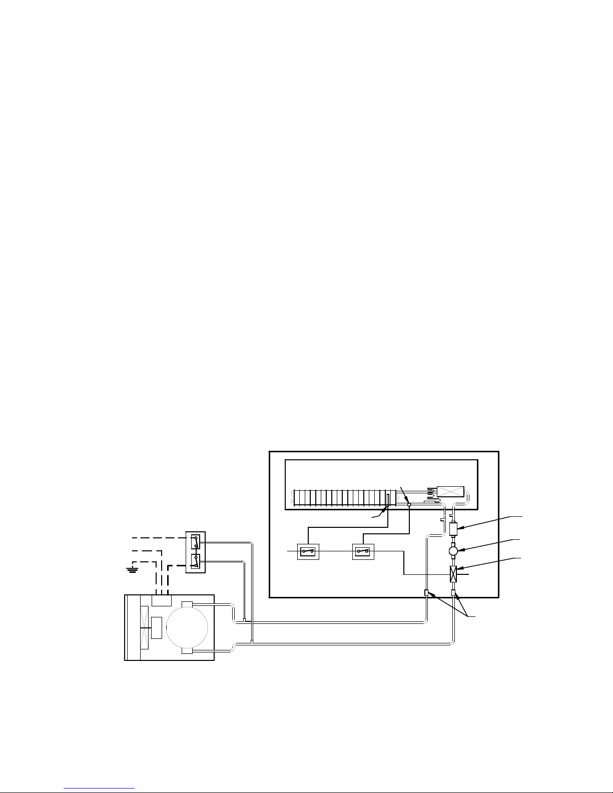
Remote Refrigeration Instruction................................................................................................8
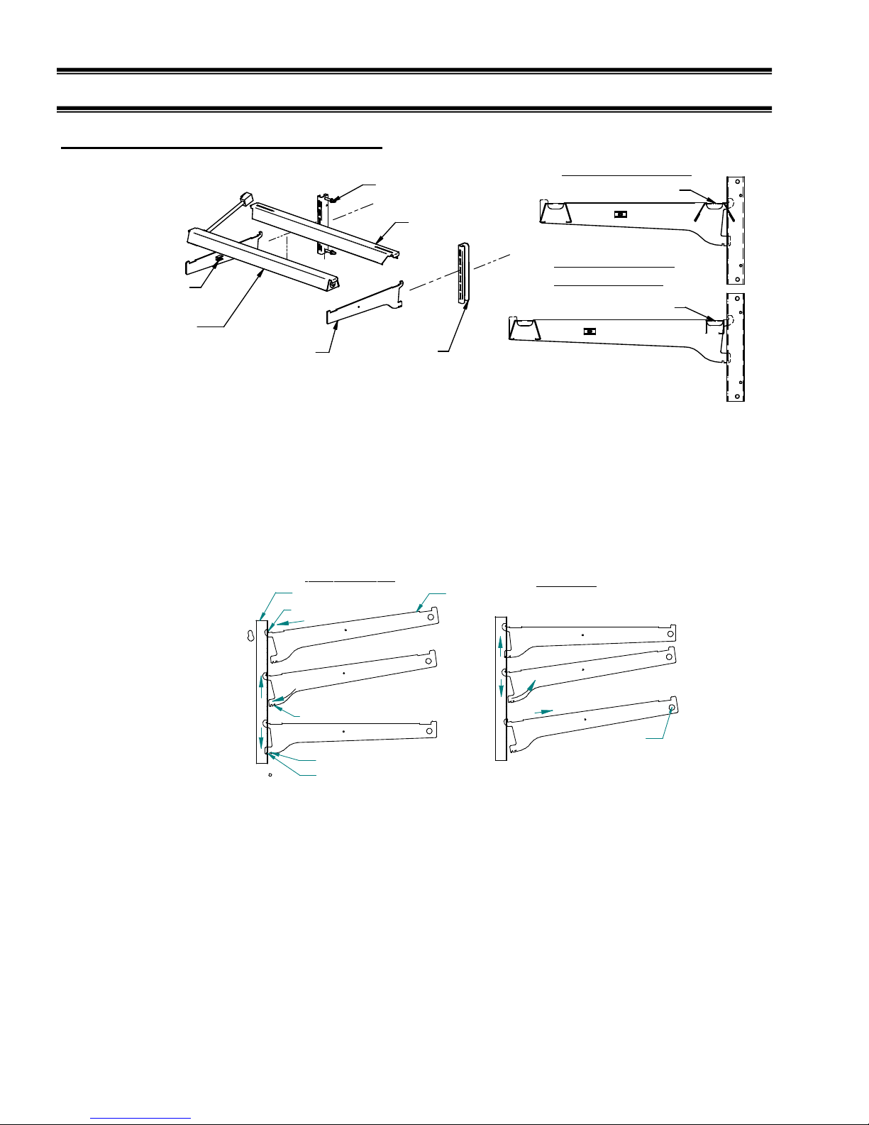
SHELVING INSTALLATION & REMOVAL.................................................................................. 9-11
Shelf Brackets & Supports......................................................................................................... 9-10
Wire Shelves ..................................................................................................................................10
Glass Shelves (Option)...................................................................................................................11
REAR DOORS ................................................................................................................................... 12-13
Top Section Rear Doors.................................................................................................................12
Bottom Section Rear Doors (Option).............................................................................................13
NIGHT CURTAIN (OPTION).................................................................................................................14
SECURITY NIGHT COVER (OPTION)...............................................................................................15
OPERATING INSTRUCTIONS ....................................................................................................... 16-17
Controls..........................................................................................................................................16
Top Section Refrigeration Louver Control.....................................................................................17
Placing Product In Case .................................................................................................................17
MAINTENANCE ......................................................................................................................................18
Top Light Bulb Replacement.........................................................................................................18
Shelf Light Bulb Replacement.......................................................................................................18
PERIODIC MAINTENANCE .................................................................................................................19
Cleaning Condenser Coil................................................................................................................19
CLEANING INSTRUCTIONS.......................................................................................................... 20-23
Daily Cleaning................................................................................................................................20
Weekly Cleaning............................................................................................................................21
Weekly Top Section Cleaning.................................................................................................. 21-22
Weekly Bottom Section Cleaning............................................................................................ 22-23
Weekly Exterior Cleaning..............................................................................................................23
SERVICE INFORMATION .............................................................................................................. 24-25
Special Service Situations..............................................................................................................24
Pre-Service Checklist.....................................................................................................................25
SALE & DISPOSAL.................................................................................................................................26
Owner Responsibility.....................................................................................................................26
REFRIGERATION & ELECTRICAL DATA.......................................................................................26
WIRING DIAGRAMS........................................................................................................................ 27-28
Self Contained................................................................................................................................27
Remote ...........................................................................................................................................28
REPLACEMENT PARTS.................................................................................................................. 29-31

- 3 -
INTRODUCTION
Thank you for purchasing a Federal Industries display case. This manual contains important instructions for
installing and servicing the Refrigerated Self-Service Merchandisers. A repair parts list and wiring diagram
are also included in the manual. Read all of these documents carefully before installing or servicing your
case.
NOTICE
Read this manual before installing your case. Keep this manual and refer to it before doing any
service on the equipment. Failure to do so could result in personal injury or damage to the case.
NOTICE
Installation and service of the electrical components in the case must be performed by a licensed
electrician.
The portions of this manual covering components contain technical instructions intended only for persons
qualified to perform electrical work.
DANGER
Improper or faulty hookup of electrical components in the case can result in severe injury or death.
All electrical wiring hookups must be done in accordance with all applicable local, regional, or
national standards.
SERIAL NUMBER
Record the model and serial numbers of the case for easy reference. Always refer to both model and serial
numbers in your correspondence regarding the case.
Case Model__________________________ Serial Number______________________
Condensing Unit Model________________ Serial Number______________________
This manual cannot cover every installation, use, or service situation. If you need additional information,
call or write us: WARRANTY/TECHNICAL SERVICE DEPARTMENT
Federal Industries
P.O. Box 290
Belleville, WI 53508
Toll Free (800) 356-4206 / WI Phone (608) 424-3331

- 4 -
WARNING LABELS & SAFETY INSTRUCTIONS
This is the safety-alert symbol. When you see this symbol on your case or in the
manual, be alert to the potential for personal injury or damage to your equipment.
Be sure you understand all safety messages and always follow recommended precautions and safe
operating procedures.
NOTICE TO EMPLOYERS
You must make sure that everyone who installs, uses, or services your case is thoroughly
familiar with all safety information and procedures.
Important safety information is presented in this section and throughout the manual. The
Following signal words are used in the warning and safety messages:
DANGER: Severe injury or death will occur if you ignore the message.
WARNING: Severe injury or death can occur if you ignore the message.
CAUTION: Minor injury or damage to your case can occur if you ignore the message.
NOTICE: This is important installation, operation, or service information. If you ignore the
message, you may damage your case.
The warning and safety labels shown throughout this manual are placed on your Federal
Industries case at the factory. Follow all warning label instructions. If any warning or safety labels
become lost or damaged, call our customer service department at 1(800) 356-4206 for replacements.
This label is located on the back of the display case. This label is located below the display pan.
CAUTION
POWER BEFORE
RISK OF ELECTRIC
SHOCK DISCONNECT
91-12340
SERVICING UNIT.
CAUTION
HAZARDOUS MOVING PARTS
DO NOT OPERATE UNIT WITH
DISPLAY PANS REMOVED.

- 5 -
PRE-INSTALLATION PROCEDURES
Inspection for Shipping Damage
You are responsible for filing all freight claims with the delivering truck line. Inspect all cartons
and crates for damage as soon as they arrive. If damage is noted to shipping crates, cartons, or if a
shortage is found, note this on the bill of lading (all copies) prior to signing.
If damage is discovered when the case is uncrated, immediately call the delivering truck line and
follow up the call with a written report indicating concealed damage to your shipment. Ask for an
immediate inspection of your concealed damage item. Crating material must be retained to show
the inspector from the truck line.
GENERAL ELECTRICAL & GROUNDING
DANGER: Improper or faulty hookup of electrical components in the
display case can result in severe injury or death.
Permanent Connected (OPTION)
-Only a licensed electrician must perform all case electrical connections.
-All electrical wiring hookups must be done in accordance with all applicable local, regional, or national
electrical standards.
-A separate circuit for each display case is required to prevent other appliances on the same circuit from
overloading the circuit and causing malfunction.
-The electrical service must be grounded upon installation.
-See the electrical data plate located at the rear of the case for proper circuit size and wire ampacity.
-The electrical connection box is accessible from the rear of the case with rear grill removed.
REAR BASE PANEL
(6) REAR PANEL SCREWS
CONDUIT OR
POWER CORD
CONNECTION .875
O
FIELD CONNECTION BOX
FLOOR CONDUIT
CONNECTION .875
O
Cord Connected (OPTION)
-A factory installed optional power cord is properly sized to the amperage requirements of the case. See the
electrical data plate located on the rear exterior of the case for the proper circuit size for each case.
- The cord is factory installed protruding from the rear corner of the case.
-A separate circuit for each display case is required to prevent other appliances on the same circuit from
overloading the circuit and causing malfunction.

- 6 -
INSTALLATION INSTRUCTIONS
Locating Display Case
The case should be located where it is not subjected to the direct rays of the sun, heating ducts, grills,
radiator, or ceiling fans, nor should it be located near open doors or main door entrances. Also, avoid
locations where there are excessive air movement or air disturbances.
The case requires a minimum of 12” clearance at the rear of the unit for air discharge. Do not locate case
with back tight against the wall.
No clearance is needed on sides of the unit.
Removing Case From Shipping Skid and General Installation
CAUTION:
Do not push or pull against the top end glass, or
door frames and do not pull on end panels when removing the case
from the skid or moving the case. Case damage or glass breakage will result.
1. Remove crate top and sides and note missing or damaged items as explained in the pre-installation
procedures outlined above.
2. Move the case as near as possible to the final location and before removing it from the shipping skid.
3. Remove the (4) brackets that secure the case to the shipping skid.
4. Prepare cabinet according to instructions in this section that pertain to your model.
5. Lift the case off of skid and into required position. Only lift the case from under the rear lip and front
bottom trim channel above the base. Note: Do not push or pull on front bottom trim channel.
6. The case must be level for proper drainage of defrost condensate to the condensate evaporator. Using
the wrench provided level and square the case as needed by adjusting the leg leveler in each corner of
base. The 6’cases also have a set of leg levelers in the center. These must be adjusted so the base is flat.
7. The leveled case must be sealed to the floor using a NSF Listed Sealant.
Cleaning
For initial setup, clean the case as outlined in the “Weekly Cleaning” section of this manual.

- 7 -
REFRIGERATION
Self Contained Models Use pressure gauges to set pressure control.
SSRC3652 SSRC5052 SSRC5952 SSRC7752
Refrigeration R404 Charge 30 OZ 32 OZ 34 OZ 36 OZ
Low Pressure Switch Cut In 82 psi 82 psi 82 psi 82 psi
Low Pressure Switch Cut Out 51 psi 48 psi 45 psi 51 psi
High Pressure Switch Cut Out 400 psi
TXV Setting (turns from full open)
(Turn screw counter clockwise to stop
for full open position) 1.5 1.5 1.5 1.5
The self-contained models are shipped from the factory with a completely operational 404A refrigeration
system and require no modifications or adjustments upon installation. Case must be installed as per the
installation section of this manual to provide proper condensing air cooling.
Self Contained Refrigeration Operation
The unit temperature is controlled by the low pressure side of a dual high/low pressure switch. The
compressor will run until either the minimum run timer times out (approx 10 min) or the suction pressure
reaches the set cut out point at which time the compressor turns off. The compressor will remain off until
the suction pressure rises and reaches the set cut in point of the pressure switch at which time the
compressor turns on.
Note: The condenser fan runs continuously.
This unit also has a defrost timer that will shut the compressor off a set number of times per day to insure a
full defrost occurs. The compressor will remain off until the either the off time is reached or until the
temperature sensor on the coil reaches a set temperature which ever happens first.
Remote Models Use pressure gauges to set pressure control.
SSRC3652 SSRC5052 SSRC5952 SSRC7752
Refrigeration R404 Charge CHARGED IN FIELD
Remote Low Press. Switch Cut In 50
Remote Low Press. Switch Cut Out 30
Remote High Press. Switch Cut Out 400 psi
TXV Setting (turns from full open)
(Turn screw counter clockwise to stop
for full open position) 1.5 1.5 1.5 1.5
Remote Models
The remote models are designed to use 404A refrigerant and shipped from the factory with the evaporator
coil, expansion valve, drier filter, sight glass and refrigerant solenoid valve. A thermostat senses evaporator
temperature and opens and closes the refrigerant solenoid valve. The solenoid valve closes and shuts off the
refrigeration flow to the unit and initiates a pump down cycle. This will allow the remote low pressure
switch to open and shut off remote compressor. The temperature control may require some adjustment by

- 8 -
installer for proper operation of unit. This unit also has a defrost timer that will shut the refrigeration
solenoid off a set number of times per day (set at factory for 3 times per day) to insure a full defrost occurs.
The solenoid will remain off until the either the off time is reached or until the temperature sensor on the
coil reaches a set temperature which ever happens first
The condensing unit is optionally supplied from the factory for remote location installation. The
condensing unit supplied from the factory will include a high low pressure switch that must be mounted
and wired by the installer. The high low pressure switch must be wired in series with the compressor power
supply as shown in diagram below. If the factory is not providing the condensing unit a high/low pressure
switch will need to be supplied by installer and installed by installer.
1. Mount condensing unit indoors as close to the remote display case as practical. The refrigeration line
should be as short as possible and must not exceed 30 feet.
2. All refrigeration and/or electrical materials between the condensing unit and display case are to be
supplied by installing contractor.
3. Route properly sized and designed refrigeration lines from the condensing unit to the cabinet.
Horizontal suction lines should be pitched downward towards the condensing unit at least ½” per 10’
run to aid the oil drainage. A “P” trap must be installed in the suction line at the foot of every riser to
insure oil return. Dry nitrogen must be used to flow through tubing while brazing refrigeration lines.
4. Suction line must be insulated the entire length with Armaflex (or equivalent). Do not run liquid line
inside insulation with suction line.
5. The remote high/low-pressure control must be mounted, wired and set pressures by the installer.
6. Leak check condensing unit, cabinet, and all connecting tubing. Cabinet and condensing unit tubing
should be checked to insure no leaks occurred during shipping or from rough handling.
Make certain all refrigeration valves are opened and evacuate system to 500 microns. Charge the
system with refrigerant type specified on the data plates.
REMOTE
HIGH LOW
PRESSURE
CONTROL
LIQUID LINE
SUCTION LINE (INSULATED)
REMOTE
CONDENSING
UNIT
EVAPORATOR COIL
DISPLAY CASE
EXPANSION
VALVE
HIGH
LOW LIQUID LINE
SOLENOID VALVE
SIGHT GLASS
DRIER/FILTER
FIELD CONNECTION
HOT
FUSED
POWER
SUPPLY DEFROST
TIMER
HOT
DEFROST
TERMINATE
TEMPERATURE
CONTROL NEUT.
TEMP. CONTROL PROBE

- 9 -
SHELVING INSTALLATION & REMOVAL
Shelf Bracket & Supports Installation
SHELF STANDARD
REAR SHELF SUPPORT
SHELF LIGHT ASSEMBLY
SHELF BRACKET
SHELF LIGHT CORD
RETAINER CLIP
SHELF STANDARD
RETAINING SCREW
OPTIONAL BOTTOM
SECTION SHELF
TOP SECTION SHELF
REAR SHELF SUPPORT
REAR SHELF SUPPORT
1. Turn the light switch to the off position. Remove rear doors as described in the “Rear Door Removal”
section of this manual to allow access to interior of case.
2. Follow the instruction in the illustration below and insert (1) of the (2) shelf brackets in the desired
shelf standard slot on one side of the case. Place the additional shelf bracket in the same shelf standard
slot on the opposite end of case. The bracket with a shelf light cord retainer clip must be on the side
with the shelf light receptacle.
0vNOTCH
6vNOTCH
4
1
2
3
4
INSTALLATION REMOVAL
23
1
TOP HOOK
BOTTOM TAB
SHELF BRACKET
SHELF STANDARD
1. Place shelf bracket top hook into desired shelf
standard slot.
2. Lift shelf bracket top hook to allow shelf bracket
bottom tab to clear shelf standard slot.
3. Swing shelf bracketbottom tab into shelf standard
slot.
4. Place the desired shelf bracket notch of 0, 6, or 12
degrees onto bottom of shelf standard slot.
1. Lift shelf bracket up to allow shelf bracket notch
to clear the bottom of shelf standard slot.
2. Swing shelf bracket bottom tab out of shelf
standard slot.
3. Drop shelf bracket down to allow shelf bracket top
hook to clear top of shelf standard slot.
4. remove shelf bracket top from shelf standard slot.
CLEAR BUMPER
TOWARDS END PANEL
3. Hang one end of shelf light housing on the front notch of a shelf bracket and then the other end of shelf
light housing on the notch of the shelf bracket on the opposite end.
NOTE: On models without shelf lights, use a shelf support instead of a shelf light housing.
4. Push shelf light cords into plastic shelf cord retainer clip located on inside of shelf bracket.

- 10 -
5. Remove the cap from the appropriate female light sockets.
IMPORTANT: Grip each side of cap firmly and wiggle and pull cap straight out of socket. Do not roll
cap during removal. Incorrect removal of cap may cause damage to electrical connection.
RIGHT WRONG
6. If the socket is not being used for a shelf light, the cap must be plugged into socket for entire light
system to operate.
7. Plug in each shelf light by aligning the male pins on the appropriate shelf light cord plugs with the
female light sockets and push together. IMPORTANT: Do not roll plug during insertion.
8. Hang one end of the shelf support on to the rear notch of one shelf bracket and then on the rear notch of
the shelf bracket on the opposite side. NOTE: If the bottom open section shelf is supplied instead of
step risers, the bottom rear support is not the same as the top rear support. See illustration above.
9. Place supplied shelving onto shelf supports as outlined in the appropriate “Shelf Installation” section of
this manual.
10. Removal of shelving is performed by following steps in reverse order.
11. The shelf standards are removable from case by removing the (2) shelf standard retaining screws
holding them to the inside wall of case.
Wire Shelves Installation
WIRE SHELF
WIRE SHELF
RETAINER CLIPS
SNAP THE REAR RAIL OF
THE WIRE SHELF INTO
RETAINER CLIPS ON
REAR SHELF SUPPORT
1. Install shelf brackets & shelf supports as described in Shelf Bracket & Supports Installation Section of
this manual.
2. Place the front of wire shelf onto front shelf light. (On front shelf support for models without shelf
lights)
3. Snap the rear of shelf into the clear plastic clips on rear shelf support.

- 11 -
Glass Shelves Installation
GLASS SHELF
SHELF STANDARD REAR SHELF
SUPPORT
SHELF LIGHT ASSEMBLY
SHELF BRACKET
GLASS SHELF
RETAINER CLIP
CORD RETAINER CLIP
PRODUCT STOP
RETAINER CLIP
SLOT
PLACE BACK SIDE OF GLASS
SHELF RETAINER CLIP INTO SLOT
IN OF REAR SHELF SUPPORT
TOP SECTION GLASS SHELF
PLACE GLASS SHELF RETAINER
CLIP OVER REAR SHELF SUPPORT
SHELF STANDARD
RETAINING SCREW
OPTIONAL BOTTOM
SECTION GLASS SHELF
CLIP LOCATED IN FAR
CORNER OF GLASS SHELF.
CLIPS FIELD INSTALLED TO GLASS.
TOP VIEW
PRODUCT STOP
PRODUCT STOP
1. For first time installation attach (2) glass shelf retainer clips to each glass shelf in location shown in
illustration. Clean area of glass where glass shelf holder is to be located with rubbing alcohol and let
air dry before installing shelf glass holder. Remove backing from tape located on flat side of glass shelf
holder. Position the glass shelf holders in the (2) far corners of glass. Repeat for each glass shelf.
2. For first time installation attach (1) product stop to each glass shelf as shown in detail above. Align the
product stop edge with the edge of the glass and push the “U” portion of the product stop on to glass lip
across the entire front of glass.
3. Attach a clear bumper on both sides of the light housing top surface for the front of the glass to set on.
This step may have already been performed at the factory for you.
4. Place front of glass shelf onto clear bumpers on front shelf light. (On front shelf support for models
without shelf lights.)
5. If clear plastic clips were factory-installed on top of rear shelf support, remove and discard clear plastic
clips.
6. For top section glass shelf set the rear of the glass shelf onto the rear shelf support so that the back side
of the glass shelf retainer sets into the slot on the rear shelf support. For optional bottom section glass
shelf set the rear of the glass shelf onto the rear shelf support so that the back side of the glass shelf
retainer straddles the rear shelf support

- 12 -
REAR DOORS
TOP SECTION REAR DOORS
UPPER TRACK
LOWER TRACK
1. LIFT UP DOOR
2 SWING BOTTOM OUT
1. Start with the outer door and lift the door upward until the bottom edge of door clears the
lower track and then swing the bottom of the door outward and down out of upper track.
2. After the outer door is removed repeat the procedure for the inner door.
3. Reverse this procedure for door reinstallation. The doors are not interchangeable.

- 13 -
BOTTOM SECTION REAR DOORS (OPTIONAL)
1. LIFT UP DOOR
2 SWING BOTTOM OUT
1. LIFT UP DOOR
2 SWING BOTTOM OUT
INNER DOOR CATCH
INNER DOOR CATCH SLOT
INNER DOOR UPPER TRACK
OUTER DOOR UPPER TRACK
OUTER DOOR LOWER TRACK
INNER DOOR LOWER TRACK
OUTSIDE DOOR SET
1. Start with the outer outside door and lift the door upward until the bottom edge of door clears
the lower track and then swing the bottom of the door outward and down out of upper track.
2. Remove the outer inside door using the same procedure.
3. The inner door set can then be removed using the same procedure starting with the inner outside
door followed by the inner inside door.
4. Reverse this procedure for door reinstallation starting with the inner inside door followed by the
inner outside door. Check that the doors slide freely.
5. Replace the outside inner door and the outside outer door. Be sure to slide the inner door catch
into the inner door catch slot for each door.
Note: None of the doors are not interchangeable and they must be replaced in the same
location that they where removed from.

- 14 -
NIGHT CURTAIN (OPTION)
NIGHT CURTAIN STRAP
NIGHT CURTAIN SNAP
SNAP
FRONT PANEL
NIGHT CURTAIN
HOLDER BRACKETS
OPENING:
1. Grab night curtain strap and lift the rolled night curtain out of the night curtain holder
brackets. Pull the night curtain across the top of case and down the front.
2. Attach the snap located under the night curtain strap on to the snap located on the front
trim.
CLOSING:
1. Grab the night curtain strap and detach the snap from the snap located in the front top trim.
2. While holding the night curtain strap allow the night curtain to roll up and place the rolled
night curtain carefully into the night curtain holder brackets.
Note: The 59”’ and 77” models have (2) night curtains.

- 15 -
SECURITY NIGHT COVER (OPTION)
SECURITY NIGHT COVER
LOCK HANDLE
(SHOWN IN LOCK POSITION)
LOCK HANDLE
(SHOWN IN LOCK POSITION)
GRAB HANDLE
GRAB HANDLE
TOP GLASS HANDLE
FRONT CLEAR DEFLECTOR
"U" RATAINER CLIP
"U" RATAINER CLIP
"U" RATAINER CLIP ON CENTER
(ON SOME MODELS)
LOCK HANDLE CATCH
LOCK HANDLE CATCH
REMOVAL:
1. Unlock the lock handles and turn handles vertical to disengage from lock handle catches.
2. Grab the front grab handles and lift the cover straight up out of the case opening.
INSTALATION:
1. Turn the lock handle so the latch handle is vertical to the top of the case.
2. Holding the grab handles place the bottom flange of the security night cover inside the “U”
retainer clips located on each side of case opening behind the front clear deflector. There
also may be a “U” retainer clip in the center of the case that must also engage the security
night cover flange.
3. Set the top flange of the security cover down against the top glass handle.
4. Turn the lock handles so they engage the lock handle catches and use the key to lock them
in place.
IMPORTANT: Cleaning the Acrylic plastic security night cover require special care to prevent hazing of
material. Lightly dust (not wipe) the surface with clean soft cloth. Then the surface can be wiped carefully
with a soft, wet cloth or chamois. The cloth or chamois must be kept free of grit by frequently rinsing in
clean water. Grease and oil can be removed with kerosene. Do not use window cleaners or kitchen scouring
compounds. DO NOT use solvents such as Acetone, Benzene, Carbon Tetrachloride, and Lacquer
Thinners. A spray wax such as Pledge or Maguire’s polish can be applied and wiped with a clean soft cloth.
The wax tends to fill in and hide small scratches

- 16 -
OPERATING INSTRUCTIONS
NOTICE: This refrigerated display case is designed to operate
in a maximum environment of 80 DEG. F and 55% relative
humidity. Exceeding these limits will cause poor case
performance and sweating of glass panels.
POWER SWITCH
LIGHT SWITCH
Controls
Power Switch
This switch controls the power to the entire unit. The switch rocker is red in the “on” position,
black in the “off” position.
Light Switch
This switch controls the power to the lighting circuit. The switch rocker is red in the “on” position,
black in the “off” position.

- 17 -
Top Section Refrigeration Louver Control
AIR CONTROL
LOUVER ASSEMBLY
AIR CONTROL
ADJUSTMENT
KNOB
AIR CONTROL
ADJUSTMENT KNOB OUT
AIR CONTROL
ADJUSTMENT KNOB IN
LOUVER CLOSED POSITION
LOUVER OPEN POSITION
The top section of this unit can be changed from a refrigerated section to a non refrigerated section by
opening or closing the louver. Unlock the louver position by loosening the control knob (turn control knob
counter clockwise) and lock the louver position by tightening the control knob (turn control knob
clockwise). Sliding the air control knob out will open the louver making the top section refrigerated and
sliding the air control knob in will close the louver making the top section non-refrigerated (see illustration
above). Even with the louver in the closed position the top section will be colder then ambient. If a
refrigerated section is required for potentially hazard food the air control louver must be completely open.
A half open louver will not allow sufficient air flow to top section. The air control louver assembly can be
placed in the case in either direction. The air control knob can either be facing the inside or the outside of
the case. The side that the air control knob is facing will not effect case operation.
NOTICE: If a top refrigerated section is required for potentially hazard food the
air control louver must be completely open. A half open louver will not
allow sufficient air flow to top section.
Placing Product into Case
-Do not exceed 75 pounds of weight per shelf. Heavy product should be distributed evenly across
the entire shelving area.
- Determine desired shelving location and angle before placing product in case. Product must be
removed to readjust shelf location and angle.
-Allow a minimum of 2” between top of product and bottom of shelf as shown in diagram below.
-Do not overhang the front or rear of shelves with product. Improper clearance in front and rear of
shelf will block the refrigerated airflow and will cause product loss.
-Do not block the slots along the front and rear air discharge slots. Covering these slots will block
the refrigerated airflow and could cause product loss.
-The display deck is removable for cleaning and can become dislodged in shipment. To ensure
proper airflow and performance of the case, make sure that the display deck is pushed
completely down into evaporation tub.
-Allow refrigerated models to run for at least two hours before placing pre-chilled product into unit.
NOTICE: CASE MUST BE STOCKED WITH PRE-CHILLED PRODUCT ONLY.
NOTICE: This refrigerated display case is designed to operate
in a maximum environment of 80 DEG. F and 55% relative
humidity. Exceeding these limits will cause poor case
performance and sweating of glass panels.

- 18 -
MAINTENANCE
Top Light Bulb Replacement
1. To remove bulb from top light housing, grip the bulb receptacle end caps at each end of bulb. Pull
the bulb receptacle end caps straight outward away from unit.
2. The bulb is inside a clear shatter proof tube with a white plastic end cap on each end. Be careful not
to allow bulb to slide out of shatter proof tube.
3. Reinstall new bulb in to the existing shatter proof tube and reuse white plastic end caps. Reinstall
bulb assembly in the same manner as described in the Bulb Removal Procedure. Be sure bulb is
secure in bulb receptacles
4. Reinstall new bulb in the same manner as described in the Bulb Removal Procedure. Be sure bulb is
secure in bulb receptacles. Note: Be sure to use a direct equivalent to the original bulb.
Shelf Light Bulb Replacement
1. All shelf light fixtures use a spring-loaded socket at one end. To remove the bulb push the bulb
towards the spring-loaded socket until the opposite ends drops out of the socket.
2. The bulb is inside a clear shatter proof tube with a black plastic cap on each end. Be careful not to
allow bulb to slide out of shatter proof tube.
3. Reinstall new bulb in to the existing shatter proof tube and reuse black plastic end caps. Reinstall
bulb assembly in the same manner as described in the Bulb Removal Procedure. Be sure bulb is
secure in bulb receptacles
Note: Be sure to use a direct equivalent to the original bulb.

- 19 -
PERIODIC MAINTENANCE
NOTICE: Condenser coil must be cleaned a minimum of twice per month to insure
proper refrigeration performance and prevent compressor failure.
Failure to clean condenser coil will void condenser warranty.
Cleaning Condenser Coil (All Self Contained Refrigerated Units)
It is very important that the Condenser coil is cleaned twice per month to insure proper refrigeration
performance and to prevent compressor failure. Failure to clean condenser coil will void condenser
warranty.
1. Disconnect power to the unit.
2. Remove the back base panel located on the back bottom of unit by removing the (6) front panel
retaining screws.
3. Carefully vacuum the front surface of condenser coil. Take care not to bend coil fins with vacuum
cleaner nozzle.
4. Reinstall back panel and retaining screws.
VACUUM FRONT
SURFACE OF
CONDENSER COIL
(6) REAR BASE
PANEL SCREWS

- 20 -
CLEANING INSTRUCTIONS
Daily Cleaning
The case should be cleaned thoroughly, as described in the weekly cleaning section, before it is
used for the first time.
NOTICE: Avoid splashing or soaking any electrical components with water to
prevent electrical damage to the case.
NOTICE: Shut off lights and power switches and remove all product from case.
Allow sufficient time for the unit to reach room temperature before
proceeding with cleaning.
NOTICE: Remove all product from case before proceeding with cleaning
procedure.
NOTICE: Acrylic front air deflector requires special washing procedures to
prevent hazing and yellowing of material.
NOTICE: This case is not designed to be cleaned by flushing.
Note: For major spills or foreign material buildup use complete weekly cleaning instructions.
Note: Detergents are not recommended and do not use abrasive cleaners or pads to prevent
scratching of surfaces.
1. Clean all foreign materials from the door opening.
2. Wipe complete interior of both the upper & lower areas of case using a damp cloth.
3. To allow easier access to clean upper section interior tilt the upper front glass open. Tilt the
front glass up by standing in front of the case and grabbing the handle at the bottom of the glass
and lifting the bottom of the glass upward. The glass can then be cleaned with common window
cleaners. Close the glass by pulling the front handle of glass down to the closed position.
4. The remaining exterior surface should be wiped down using any ammoniated cleaners or soapy
warm water.
5. IMPORTANT: Cleaning the clear acrylic plastic front air deflector require special care to
prevent hazing and yellowing of material. Lightly dust (not wipe) surface with clean soft cloth.
Then the surface can be wiped carefully with a soft, wet cloth or chamois. The cloth or chamois
must be kept free of grit by frequently rinsing in clean water. Grease and oil can be removed
with kerosene. Do not use window cleaners or kitchen scouring compounds. DO NOT use
solvents such as Acetone, Benzene, Carbon Tetrachloride, and Lacquer Thinners. A spray wax
such as Pledge or Maguire’s polish can be applied and wiped with a clean soft cloth. The wax
tends to fill in and hide small scratches.
.
Other manuals for SSRC Series
1
This manual suits for next models
4
Table of contents
Other Federal Refrigerator manuals
Popular Refrigerator manuals by other brands

Scan Cool
Scan Cool DA 320 X user manual

Minusforty
Minusforty Mortuary instruction manual

Magic Chef
Magic Chef MCBM920W user manual

TriStar
TriStar KB-7147 instruction manual

Beef Eater
Beef Eater BS28130 Assembly and operating instructions

Welbilt
Welbilt Delfield 400P Series Installation, operation and maintenance manual

Scan Cool
Scan Cool DKS 63 BE user manual

V-ZUG
V-ZUG Ideal operating instructions

Hillphoenix
Hillphoenix 05DMA Installation & operating handbook

Range Master
Range Master RDXD18IV/C User guide & installation & service instructions

Lec+
Lec+ TF60185WTD W user manual

Magic Chef
Magic Chef MCBR170BF user manual