Feider Machines IOTA User manual

ORIGINAL INSTRUCTIONS >EN
HEAVY-DUTY PORTABLE
THICKNESS PLANER
IOTA
USER GUIDE
CAUTION: Read the instructions before using the machine!

CONTENTS
1. INTENDED USE....................................................................................................3
2. SAFETY INSTRUCTIONS ....................................................................................3
3. KNOW YOUR PRODUCT.....................................................................................6
4. ASSEMBLY AND ADJUSTMENT ........................................................................
.....................................................................................................
.......................................................................................................
..................................................................................................
..........................................................................................................
..................................................................
9
5. BEFORE USE 12
6. OPERATION 13
7. MAINTENANCE 17
8. TROUBLESHOOTING..........................................................................................21
9. DISPOSAL 22
10. DECLARATION OF CONFORMITY 23
11. WARRANTY.....................................................................................................
24
12. PRODUCT FAILURE........................................................................................
25
13. WARRANTY EXCLUSIONS .............................................................................
26

1. INTENDED USE
Your FEIDER Heavy-Duty Portable Thickness Planer IOTA has been designed for wood planning
applications. This tool is intended for professional use.
2. SAFETY INSTRUCTIONS
The definitions below describe the level of severity for each signal word. Please read the manual
and pay attention to these symbols.
DANGER: Indicates an imminently hazardous situation which, if not avoided, will result in
death or serious injury.
WARNING: Indicates a potentially hazardous situation which, if not avoided, could result in
death or serious injury.
CAUTION: Indicates a potentially hazardous situation which, if not avoided, may result in
minor or moderate injury.
NOTICE: Indicates a practice not related to personal injury which, if not avoided, may result in
property damage.
Denotes risk of electric shock.
Denotes risk of fire.
2.1 GENERAL POWER TOOL SAFETY WARNINGS
WARNING! When using electric tools basic safety precautions should always be followed to
reduce the risk of fire, electric shock and personal injury including the following:
Read all these instructions before attempting to operate this product and save these instructions.
1 - Keep work area clear
- Cluttered areas and benches invite injuries.
2 - Consider work area environment
- Do not expose tools to rain.
- Do not use tools in damp or wet locations.
- Keep work area well lit.
- Do not use tools in the presence of flammable liquids or gases.
3 - Guard against electric shock
- Avoid body contact with earthed or grounded surfaces (e.g., pipes, radiators, ranges, refrigerators).
4 - Keep other persons away
- Do not let persons, especially children, not involved in the work touch the tool or the extension cord and
keep them away from the work area.
5 - Store idle tools
- When not in use, tools should be stored in a dry locked-up place, out of reach of children.
6 - Do not force the tool
- It will do the job better and safer at the rate for which it was intended.
7 - Use the right tool
- Do not force small tools to do the job of a heavy-duty tool.
- Do not use tools for purposes not intended; for example, do not use circular saws to cut tree limbs or logs.
8 - Dress properly
- Do not wear loose clothing or jewellery, they can be caught in moving parts.
- Non-skid footwear is recommended when working outdoors.
3

- Wear protective hair covering to contain long hair.
9 - Use protective equipment
- Use safety glasses.
- Use face or dust mask if working operations create dust.
10 - Connect dust extraction equipment
- If the tool is provided for the connection of dust extraction and collecting equipment, ensure these are
connected and properly used.
11 - Do not abuse the cord
- Never yank the cord to disconnect it from the socket. Keep the cord away from heat, oil and sharp edges.
12 - Secure work
- Where possible use clamps or a vice to hold the work. It is safer than using your hand.
13 - Do not overreach
- Keep proper footing and balance at all times.
14 - Maintain tools with care
- Keep cutting tools sharp and clean for better and safer performance.
- Follow instruction for lubricating and changing accessories.
- Inspect tool cords periodically and if damaged have them repaired by an authorized service facility.
- Inspect extension cords periodically and replace if damaged.
- Keep handles dry, clean and free from oil and grease.
15 - Disconnect tools
- When not in use, before servicing and when changing accessories such as blades, bits and cutters,
disconnect tools from the power supply.
16 - Remove adjusting keys and wrenches
- Form the habit of checking to see that keys and adjusting wrenches are removed from the tool before
turning it on.
17 - Avoid unintentional starting
- Ensure switch is in "off" position when plugging in.
18 - Use outdoor extension leads
- When the tool is used outdoors, use only extension cords intended for outdoor use and so marked.
19 - Stay alert
- Watch what you are doing, use common sense and do not operate the tool when you are tired.
20 - Check damaged parts
- Before further use of tool, it should be carefully checked to determine that it will operate properly and
perform its intended function.
- Check for alignment of moving parts, binding of moving parts, breakage of parts, mounting and any other
conditions that may affect its operation.
- A guard or other part that is damaged should be properly repaired or replaced by an authorized service
centre unless otherwise indicated in this instruction manual.
- Have defective switches replaced by an authorized service centre.
- Do not use the tool if the switch does not turn it on and off.
21 - Warning
- The use of any accessory or attachment other than one recommended in this instruction manual may
present a risk of personal injury.
22 - Have your tool repaired by a qualified person
- This electric tool complies with the relevant safety rules. Repairs should only be carried out by qualified
persons using original spare parts, otherwise this may result in considerable danger to the user.
2.2 SPECIFIC SAFETY RULES FOR OPERATION
⚫Wear protective hair covering to contain long hair.
⚫When not in use, tools should be stored in a dry locked up place, out of reach of children.
⚫Never use the machine without the appropriate guard in place and correctly adjusted.
⚫Do not use knives which are blunt as this increases the danger of kickback.
⚫Do not do the following operations:
➢stopped work (i.e., any cut which does not involve the full work piece length).
➢recesses, tenons or molds.
➢planning of badly bowed wood where there is inadequate contact on the infeed table.
⚫To avoid injury, never rotate the cutterhead directly with your hands.
⚫Keep hands away from the underside of the cutterhead carriage.
⚫Never clear clogs, make cutter knife replacement, or any other repairs/adjustments with unit plugged
in.
4

⚫Make certain that the switch is in the "OFF" position before connecting plug to a power source.
⚫Stay alert—never operate the unit when tired or under the influence of drugs, alcohol, or medication.
⚫Do not use it in dangerous environments. Do not use near flammable substances, in damp or wet
locations, or exposed to rain.
⚫Never plane material which is shorter than 304.8 mm (12") narrower than 19.05 mm (3/4"), or wider
than 304.8 mm (12") or thinner than 12.7 mm (1/2").
⚫Exhaust chute: remove shavings with brush or vacuum after power has been shut off and
cutterhead has stopped rotating.
⚫Always locate the planner with proper clearance on the outfeed side of the unit to prevent pinching or
binding of the workpiece against any obstacle.
WARNING: We recommend the use of a residual current device with a residual current
rating of 30mA or less.
•Check the settings of the protection and the springs during assembly, so that the device is in perfect
condition before use.
•Use blades that are well sharpened and maintained.
•Use only cutting blades designed for this machine.
•Any part of the tool not used for planning should be adjusted to protect it.
•Inspect anti-kickback devices and spindle feed speeds to ensure safe operation.
•Wear protective gear, which may include:
oHearing protection, to reduce the risk of induced hearing loss.
oRespiratory protection, to reduce the risk of inhaling harmful dust,
oGloves for handling the cutting block and raw materials, to reduce injuries from sharp edges.
2.3 RESIDUAL RISKS
In spite of the application of the relevant safety regulations and the implementation of safety devices,
certain residual risks cannot be avoided. These are:
⚫Impairment of hearing
⚫Risk of personal injury due to flying particles.
⚫Risk of burns due to accessories becoming hot during operation.
⚫Risk of personal injury due to prolonged use.
⚫Risk of dust from hazardous substances.
2.4 WARNING SYMBOL
WARNING! To reduce the risk of injury, the user must read the instruction manual
before use.
Wear ear protection.
Wear safety glasses or goggles.
Wear a dust mask.
5

Do not expose the tool to rain or high humidity or leave outdoors while it is raining.
WARNING: do not carry or use it as handle
Max. planning width 318 mm.
Keep hands away from the cutterhead!
This product requires a two-person lift-use proper lifting techniques.
Turning direction of cutter block.
3. KNOW YOUR PRODUCT
3.1 THE PACKAGE CONTAINS
1x Heavy-duty planer
1x Open ended key (8/10 mm)
1x Push sticker
1 x Dust extraction adapter
1 x Gauge
1 x 2.5mm hex wrench
1 x 5mm hex wrench
1 x Instruction manual
♦Check for damage to the tool, parts or accessories which may have occurred during transport.
♦Take the time to thoroughly read and understand this manual prior to operation.
6

3.2 PRODUCT FEATURES (FIG. A)
7

1 Cutter head adjustment handle
2 Carrying handle
3 Depth scale pointer
4 Depth scale
5 Handholds
6 Mounting holes
7 In-feed extension table
8 Material removal depth scale
9 ON/OFF switch
10 Circuit overload switch
11 Push stick
12 Adjustable scale
13 2.5mm hex wrench
14 5mm hex wrench
15 Open ended key
16 Gauge
17 Cord wrap
18 Dust extraction adaptor
19 Base
20 Depth stop
21 Tool tray
42 Top bar
3.3 TECHNICAL DATA
Voltage: 220-240 VAC
Frequency: 50-60 Hz
Power input: 1800 W
No-load/Rated speed :10000/min
Feed Speed: 8 m/min
Cutting height (max.): 5-153 mm
Planer width (max.): 304 mm
Maximum cutting depth (for max. board width of 152 mm): 3 mm
Weight: 27kg
Sound power level: 108.3 dB(A) K= 3dB(A)
Sound pressure level: 95.3 dB(A) K= 3dB(A)
Sound pressure level (near ear): 100.6 dB(A) K= 3dB(A)
Information:
- The declared vibration total value has been measured in accordance with a standard test method and
may be used for comparing one tool with another;
- The declared vibration total value may also be used in a preliminary assessment of exposure.
Warning
- The vibration emission during actual use of the power tool can differ from the declared total value
depending on the ways in which the tool is used;
- Need to identify safety measures to protect the operator that are based on an estimation of exposure in
the actual conditions of use (taking account of all parts of the operating cycle such as the times when
the tool is switched off and when it is running idle in addition to the trigger time).
8
4. ASSEMBLY AND ADJUSTMENT
WARNING: To reduce the risk of serious personal injury, turn tool off and disconnect tool from power
source before making any adjustments or removing/installing attachments or accessories. Before
reconnecting the tool, depress and release the trigger switch to ensure that the tool is off. An accidental
start-up can cause injury.
WARNING: Do not use the top bar (42) as handle to carry this machine by one people, or serious
injury could result
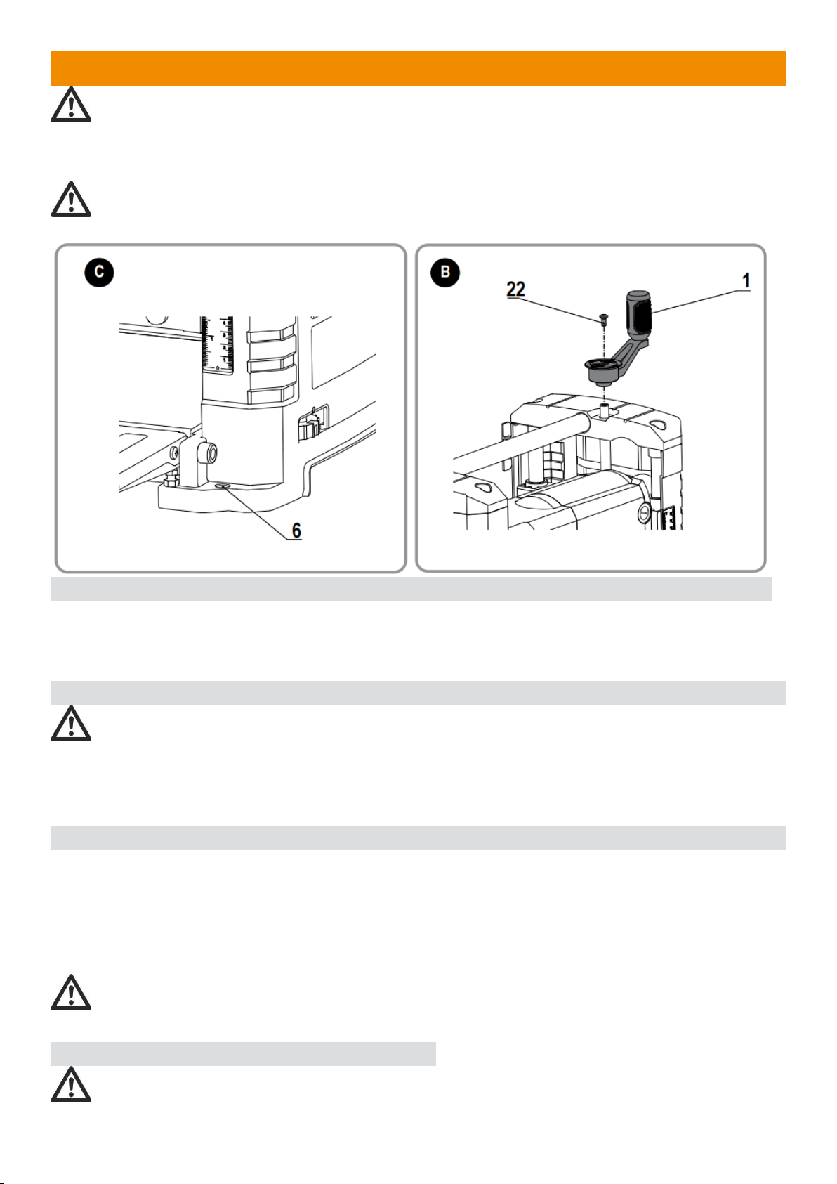
4.1INSTALLING THE CUTTER HEAD ADJUSTMENT HANDLE (FIG. B)
1) Attach the cutter head adjustment handle (1) to the planer and fasten with flower pan head screw M6 x
12 (22).
2) Tighten the flower pan head screw M6 x 12 (22), using the hex-wrench.
4.2 TRANSPORTING THE PLANER (FIG A)
WARNING: For your own safety, it is recommended that two people carry this machine or severe
injury could result. When moving your planer, hold it by hand indentation (5) at the base of the planer.
When transporting or storing the planner, use the cord wrap (17) located in the back of the tool to keep the
cord in place.
4.3 BENCH MOUNTING (FIG. A, C)
To facilitate bench mounting, mounting holes (6) are provided on the four corners of your planer as shown
in Figures A and C.
Always mount your planer firmly to a secure surface to prevent movement. To enhance the tool’s portability,
it can be mounted to a piece of 12.7 mm (1/2") or thicker plywood which can then be clamped to your work
support or moved to other work areas and reclamped.
NOTE: If you elect to mount your planer to a piece of plywood, make sure that the mounting screws don’t
protrude from the bottom of the wood. The plywood must sit flush on the work support.
CAUTION: The mounting surface should not be warped or otherwise uneven.
4.4 ASSEMBLY AND ADJUSTMENTS
Warning: To reduce the risk of serious personal injury, turn tool off and disconnect tool from power
source before making any adjustments or removing/installing attachments or accessories. An accidental
9

start-up can cause injury.
4.5 TABLE EXTENSIONS (FIG. D)
Before using your planer, fold down the table extensions in the front and back of the tool. After extended
use, the table extensions may be slightly out of level.
NOTE: The outside edges of the extension tables are level with the base while the inside edges (closest to
the cutterhead) are below the edge of the base. This is set at the factory to reduce unnecessary friction
between the material and the table while providing adequate support at the two points (those farthest from
the cutterhead) on the tables that are integral to snipe prevention.
4.6 INSTALLING THE DUST CHUTE (FIG. E-H)
1) Loosen Screws
♦Using the hex wrench (included), loosen the two marked screws (24) located at the rear of the cutter
head assembly and do not remove them.
2) Align Notches with Screws
♦Align the two notches (25) on the dust chute (18) to the two loosened screws (24).
3) Align Slots with Hooks
♦Align the two slots (26) with the two hooks (27) on the machine. If the dust chute is a little deformed, it
may be necessary to use some pressure to ensure that the slots and hooks match properly.
10

4) Tighten Screws
♦Tighten the two screws (24) that secure the dust chute (18) to the rear of the cutter head assembly.
Attach Dust Port
♦Attach the dust port (28) to the dust chute (18).
♦Attach dust port (28) to a dust collector. Refer to dust collector owner’s manual for correct procedure and
safety information.
4.7 DEPTH ADJUSTMENT (FIG. I)
The depth adjustment scale (4) indicates the finished thickness of your workpiece. One rotation of the depth
adjustment crank is equal to 1.6 mm (1/16"); half a rotation is equal to 0.8 mm (1/32"), etc.
1) To Set the Finished Thickness (Fig. B)
♦Adjust the thickness. Turn the depth adjustment handle (1) clockwise to lower the cutterhead. Turn the
handle counterclockwise to raise the cutterhead. One full rotation of the handle moves the cutterhead 1.6
mm (1/16").
2) Fine Adjustments
The depth adjustment handle allows for fine adjustments, from 0.4 mm (1/64") to 1.6 mm (1/16").
Fine adjustments are ideal for “shaving” small amounts from your material. For example, if your planed
workpiece measures 77.8 mm (3-1/16") thick, but should be 76.2 mm (3") thick, adjust your planer to
remove the excess 1.6 mm (1/16") as follows:
1) Plane and measure your workpiece. In this example, the starting thickness is 77.8 mm (3-1/16").
2) Turn the circular label on the depth adjustment handle until the “0” mark aligns with the arrow on the
top of the tool. Do not make any other adjustments to the planner.
11

3) Turn the depth adjustment handle clockwise until the 1.6 mm (1/16") mark aligns with the arrow.
4) Plane your workpiece. The final thickness should be 76.2 mm (3").
4.8 TURRET STOP (FIG. B, J)
♦Your planer is equipped with a turret stop (20) , for planning multiple boards to the same pre-set depth.
Stops are set at 0", 1/4" (6.4 mm), 1/2" (12.7 mm), 3/4" (19 mm), 1" (25.4 mm) and 1-1/4"(32 mm).
4.9 TO SET THE MINIMUM DEPTH TO WHICH THE CARRIAGE CAN
TRAVEL WITH THE TURRET STOP
♦Be sure the carriage is set above 1–1/4” (32 mm) before trying to set the turret stop.
♦Turn the turret stop until the desired thickness setting shows.
♦Unlock the carriage lock lever and lower the carriage.
♦Plane the workpiece at desired increments until the correct final thickness is achieved.
5. BEFORE USE
♦Before using the tool for the first time, it is recommended to receive practical information.
♦Always check that the supply voltage is the same as the voltage indicated on the nameplate of the tool.
♦Use suitable detectors to find hidden utility lines or call the local utility company for assistance (contact
with electric lines can lead to fire or electrical shock; damaging a gas line can result in an explosion;
penetrating a water pipe will cause property damage or an electrical shock).
♦Do not work materials containing asbestos (asbestos is considered carcinogenic).
♦Dust from material such as paint containing lead, some wood species, minerals, and metal may be
harmful (contact with or inhalation of the dust may cause allergic reactions and/or respiratory diseases to
the operator or bystanders); wear a dust mask and work with a dust extraction device when connectable.
♦Certain kinds of dust are classified as carcinogenic (such as oak and beech dust) especially in
conjunction with additives for wood conditioning; wear a dust mask and work with a dust extraction
device when connectable.
♦Follow the dust-related national requirements for the materials you want to work with.
♦Do not clamp the tool in a vice.
♦Use completely unrolled and safe extension cords with a capacity of 16 Amps.
WARNING: Your heavy-duty portable thickness planner has been designed for professional wood
planning applications.
DO NOT use under wet conditions or in the presence of flammable liquids or gases.
DO NOT let children meet the tool. Supervision is required when inexperienced operators use this tool.
♦Young children and the infirm. This appliance is not intended for use by young children or infirm persons
without supervision.
♦This product is not intended for use by persons (including children) suffering from diminished physical,
sensory, or mental abilities; lack of experience, knowledge, or skills unless they are supervised by a
person responsible for their safety. Children should never be left alone with this product.
ELECTRICAL SAFETY
Only one voltage is applicable to this tool. Be sure to check that the power supply corresponds to the
voltage on the rating plate.
When the power cord is damaged, or if the replacement of the supply cord is necessary, have it sent to
SWAP service center for replacement to specially prepared cables.
USING AN EXTENSION CABLE
If an extension cable is required, use an approved 3–core extension cable suitable for the power input of
this tool (see Technical Data). The minimum conductor size is 1.5 mm2; the maximum length is 30 m.
When using a cable reel, always unwind the cable completely.
12
6. OPERATION
Instructions for Use
WARNING: Always observe the safety instructions and applicable regulations.
WARNING: To reduce the risk of serious personal injury, turn the tool off and disconnect the tool
from power source before making any adjustments or removing/installing attachments or accessories. Be
sure the trigger switch is in the OFF position. An accidental start-up can cause injury.
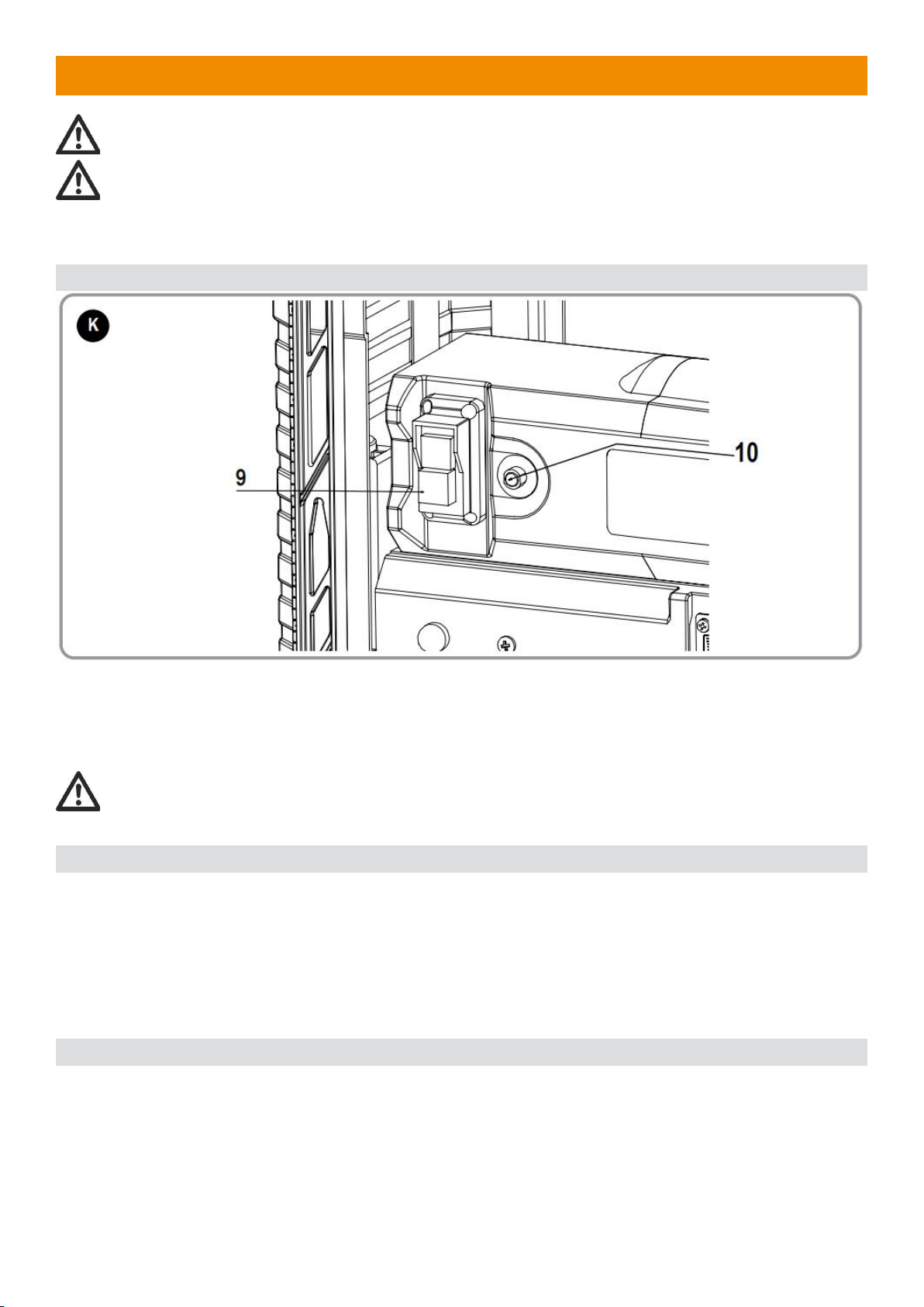
6.1 ON/OFF SWITCH (FIG. K)
♦The workpiece should not be in contact with the cutterhead when switching on. To turn it on, press the
green start button of switch 9 (Fig. K). The tool now works in continuous operation.
♦Allow the motor to reach full speed before feeding the workpiece.
♦Allow the blades to cut freely. Do not force.
♦To switch off, press the red stop button of the switch (9).
WARNING: Always turn off the tool when work is finished and before unplugging.
6.2 PUSH STICK (FIG.A)
Use only the push stick provided by the manufacturer.
♦This push stick (11) provides sufficient distance of the hand from the blade.
♦Never use a damaged or cut push stick. A damaged push stick may break causing your hand to slip into
the blade.
♦If small workpieces are inserted by hand, there is an increased risk of injury. It’s recommended to use the
push-stick. Keep your hand at a safe distance from the blade.
Always keep the push stick in its store place when not in use.
6.3 OVERLOAD PROTECTOR/RESET BUTTON (FIG. K)
This planer is equipped with an overload protector/reset button (10) which will automatically “trip” and cause
the planer to shut down if the motor is overloaded due to continuous heavy cutting.
The planer overload protector can only be reset manually by the user after the planer has been allowed to
adequately cool. Allow 15–30 minutes.
Should the overload protector “trip”:
♦Turn switch off (O).
♦Raise carriage and remove board.
♦After 15–30 minutes, reset overload protector by pushing the reset button (10) beside switch. An
audible click will indicate the overload protector is reset. Once the button is reset, the tool may be started
13

and operated as normal.
♦If motor has cooled, button will remain in.
6.4 MATERIAL REMOVAL DEPTH SCALE (FIG. L)
Your planer is equipped with a material removal gauge (8). It is used to indicate the amount of wood that
will be removed in one pass with the carriage set at its current height.
TO USE THE MATERIAL REMOVAL DEPTH SCALE
♦WARNING: During the initial cutting for the new tool, it is recommended that the first cut depth adjustment
shall be less than 1.5mm.
♦Be sure the wood is lying flat against the base of the planer. If the material is inserted at an angle, the
reading may be inaccurate.
♦Crank the carriage down on the material until the material removal bar engages the wood. You will see
the red arrow begin to move up the scale indicating the amount of material to be removed with the
carriage at that height.
♦Adjust the carriage height until the desired depth of cut appears on the scale.
♦Pull the material out from under the carriage.
♦Turn the unit on and feed your material into the cutterhead.
6.5 ANTI-KICKBACK DEVICE (FIG.Z)
14

Your planer is equipped with an anti-kickback (43) to prevent backsliding when planning materials.
How to check anti-kickback
Crank the carriage up to the top position, check all 22pcs anti-kickback pieces to make sure their
orientations are consistent and low in the front and high in the back.
6.6 PLANING BASICS
Proper Planning Technique
WARNING: DO NOT TURN THE UNIT ON WITH THE MATERIAL ALREADY INSERTED UNDER
THE CARRIAGE. WAIT UNTIL THE ROLLERS AND cutterhead ARE UP TO FULL SPEED BEFORE
FEEDING YOUR MATERIAL INTO THE MACHINE.
To Plane Your Material
Your planer works best on lumber with at least one flat surface. If both sides of your workpiece are rough,
use a jointer to level one face.
Always support the workpiece adequately. The maximum depth of cut your planer can take in one pass is
3.2 mm (1/8") [on material less than 152 mm (6") wide].
Never attempt to modify your planer to take a deeper cut.
Follow the depth/width of cut guidelines shown in parameter list for best results.
• Lower the carriage to the desired height for your first pass.
• Turn the unit on and feed the material into the feed rollers.
• Examine the finished cut and adjust the carriage to the appropriate height for your next pass.
See the Troubleshooting Guide at the end of this section for more information.
WARNING: Do not place your body between the workpiece and a stationary structure while the
material is feeding out. Personal injury and/or damage to the work piece may occur.
WARNING: This tool is designed to plane only wood. Do not try to plane materials other than wood.
WARNING: Check and make sure the workpiece is free of metal debris before planning. If the
workpiece penetrated by metal parts has started to be planned, stop the machine immediately to
check whether the blades need to be replaced, and contact the local service center for help if
necessary.
WARNING: Never plane wood which is shorter than 304.8 mm (12") in length.
WARNING: Plane only wood that is free from foreign objects, with no loose knots and as few tight
knots as possible. Do not plane wood that is severely warped, twisted, knotted, or bowed.
WARNING: Do not feed wood across the grain.
NOTE: For best results, plane both sides of the workpiece to reach the desired thickness. For example, if
you need to remove 3.2 mm (1/8") from your workpiece, remove 1.6 mm (1/16") from each side. This not
only allows the workpiece to dry with an even moisture content, but it also produces finer cuts.
NOTE: Always plane in the direction of the grain. Planning material less than 19.0 mm (3/4") wide is not
recommended. If you must plan narrow material, group the pieces together and plane them as one wide
workpiece whenever possible.
Minimum/Maximum Width/Height/Depth
NOTE: Always plane in the direction of the grain. Always support the workpiece adequately. Planning
material less than 3/4" (19 mm) wide is not recommended. If you must plane narrow material, group several
pieces together and plane them as one wide workpiece whenever possible. The maximum depth of cut your
planer can take in one pass is 1/8" (3 mm) [on material less than 3" (76 mm) wide]. Never attempt to modify
your planer to take a deeper cut. Follow the recommended depth/width of cut guidelines shown in
parameter list for best results.
15
6.7 SNIPE
Snipe is a depression made when an unsupported end of your material drops toward the floor, causing the
opposite end to lift into the cutterhead.
TO AVOID SNIPE
Feed the workpiece into the planer so it is level and always remains flat against the base.
Keep long workpieces level throughout planning operation by receiving or “catching” them from the rear of
the planer.
WARNING: Do not place your body between the workpiece and a stationary structure while the
material is feeding out. Personal injury and/or damage to the work piece may occur.
6.8 TWISTED, CUPPED AND BOWED WOOD
If both sides of your material are very rough or if the material is cupped, bowed, or twisted, the planer may
not produce the desired result. Ideally, you should have at least one level face/surface on your material
before you plane. Your thickness planer will work best with material that has been run through a jointer to
produce one flat surface. If you do not have at least one flat surface or a jointer, see the following
recommendations:
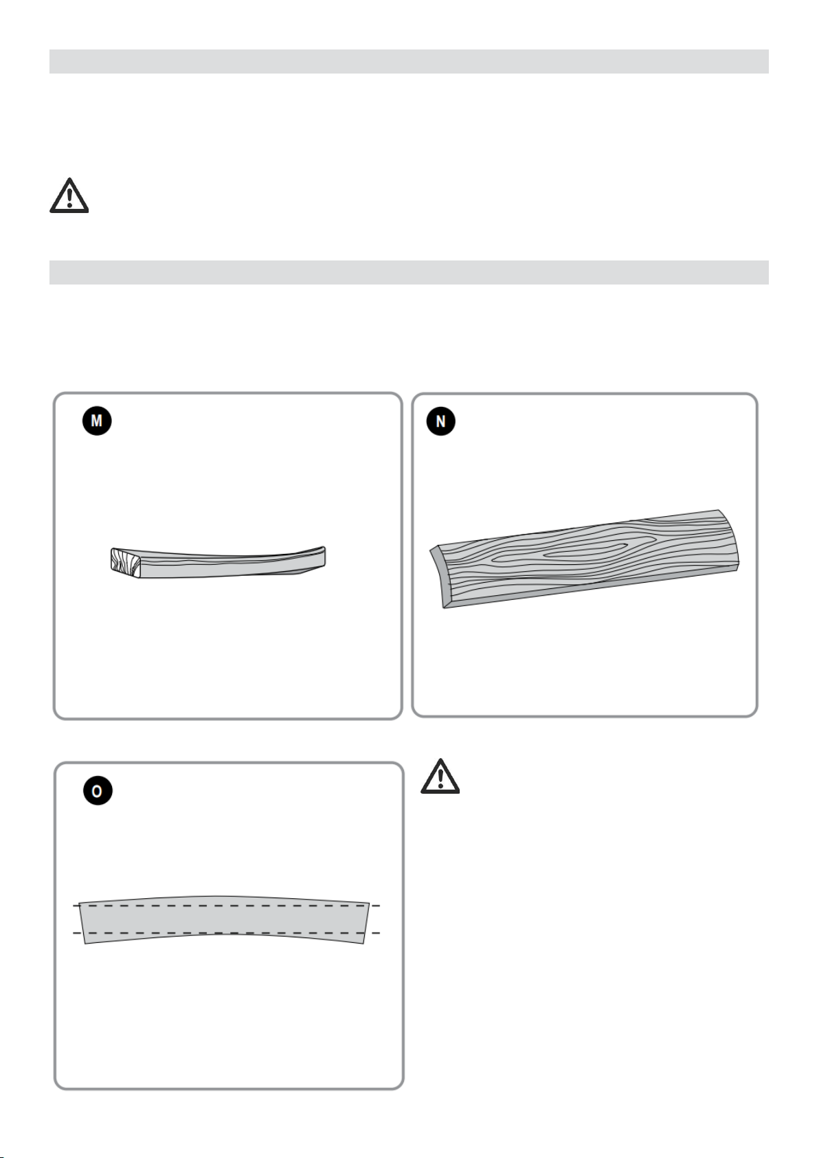
1) To Plane Twisted Wood (Fig. M–O)
WARNING: twisted wood may jam your
thickness planer. If a jam occurs, turn the power off,
disconnect the power supply and raise the carriage
to release the material from the cutterhead.
To Plane Only Slightly Twisted Material (Fig. M):
Plane both sides alternating from one to the other
until the desired thickness is reached.
To Plane Cupped Wood (Fig. N)
To obtain the best possible results with cupped
wood: Rip the material down the middle and plane it
as two
separate pieces.
NOTE: Ripping the material reduces the severity of
the cup and allows the machine to deliver better
results. More material will be removed on cupped
wood to achieve the desired thickness than on a
normal board.
If Ripping the Material is not an Option:
16

Plane one side of the material until flat, then plane the opposite side until flat (refer to Fig. O).
NOTE: Do not flip the board back and forth between each pass as recommended by the general planning
directions.
To Plane Bowed Wood (Fig. P)
The feed rollers and cutterhead in your planer will push the bow out of the material as it feeds. When the
material exits the planer, the pressure of the rollers and cutterhead will release allowing the wood to spring
back into a bowed formation. To properly remove the bow, use a jointer.
7. MAINTENANCE
Your power tool has been designed to operate over a long period of time with a minimum of maintenance.
Continuous satisfactory operation depends upon proper tool care and regular cleaning.
♦Regularly clean the ventilation slots in your tool using a soft brush or dry cloth.
♦Regularly clean the motor housing using a damp cloth. Do not use any abrasive or solvent-based cleaner.
This machine is not user serviceable. If problems occur, contact an authorized repair agent.
7.1 PERIODIC MAINTENANCE
1) Routinely check the tool for damage or broken parts.
2) Clean the unit of dust and debris that has collected in all accessible areas of the planer from planning
wood material.
3) Wipe off infeed and outfeed rollers.
4) Clean base table. Light waxing will help wood material pass through the planer.
5) Evaluate blade sharpness condition. Replace as necessary.
6) Gauge Calibration, check thickness gauge calibration and turret stop calibration.
7) Check brushes for wear and replace as necessary.
17
7.2 CHANGING BLADES (FIG. Q–U)
WARNING: use only cutting blades designed
for this machine.
WARNING: Wear gloves when changing
blades because of sharp edges. This machine is
equipped with a cutterhead which holds two blades.
For new blades contact SWAP or an authorized
service organization.
WARNING: Sharp edges.
WARNING: The blades can be re-sharpened
max. 3 mm down from their original size. If the
blade size has decreased by more than 3mm, the
blades must be replaced. The blades can be re-
sharpened at 42 °.
18
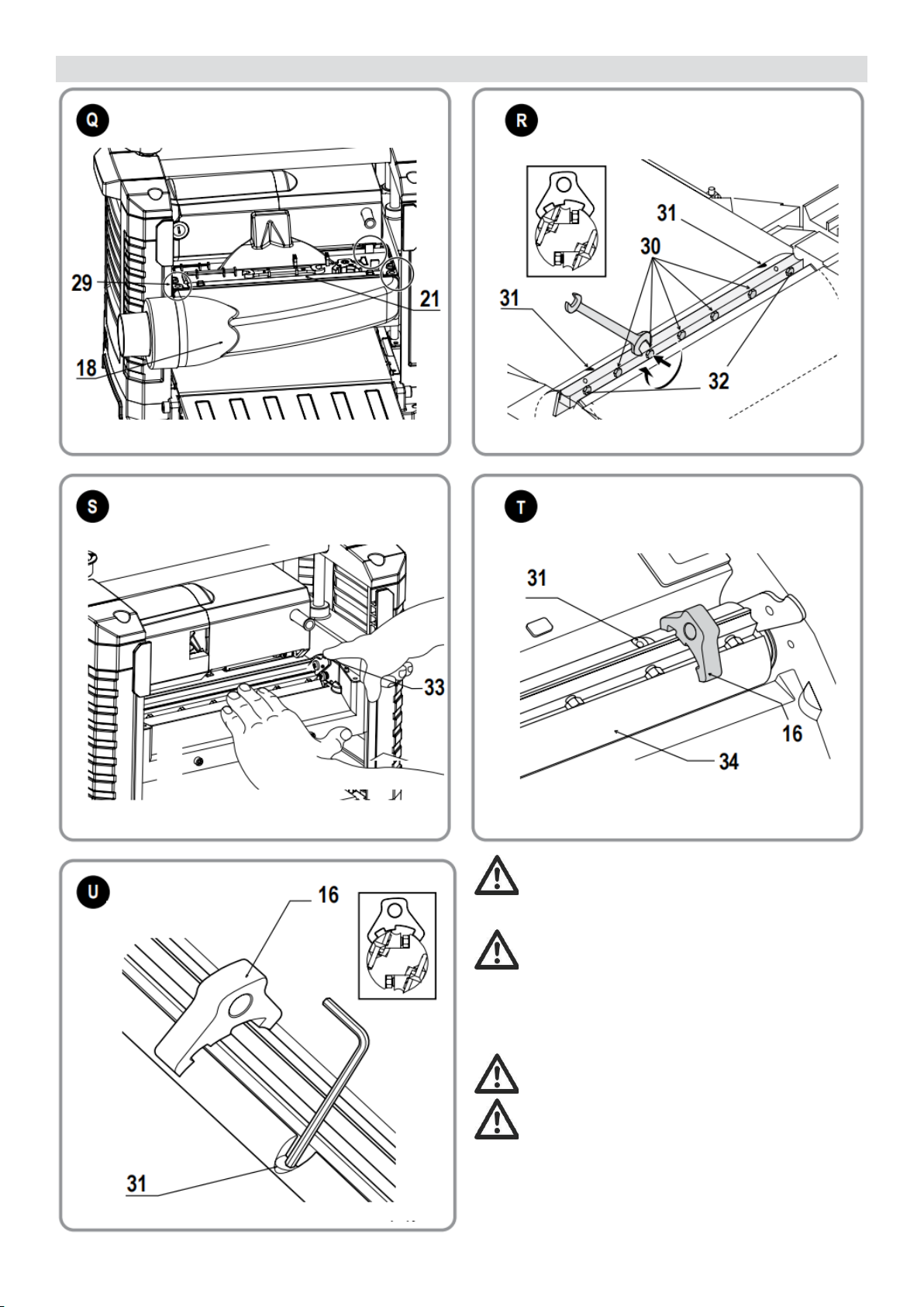
7.3 REMOVING THE BLADES (FIG. Q–U)
1) Adjust the depth of the cut to approx. 75 mm.
2) Loosen the screws (24), then rotate and remove the dust extraction adaptor (18).
3) Remove the two hex screws (29) (Fig. Q) and carefully remove the tool tray (21) to expose the blades.
4) Carefully rotate the cutterhead (34) (Fig. T) until the first blade becomes visible.
5) Loosen the seven blade clamping screws (30), (32) (Fig. R) using the wrench supplied.
6) Remove the blade from the cutterhead for re-sharpening or replacement.
7) Press the cutterhead locking lever (33) (Fig. S) and slowly rotate the cutterhead until the other blade
can be removed.
EMOVING THE BLADES (FIG. Q–U)
7.4 REPLACING THE BLADES (FIG. R–U)
WARNING: Make sure that the cutting blades are properly adjusted. Do not allow the blades to
protrude from the cutterhead by more than 1.1mm.
NOTE: Before installing the knife, ensure the cutterhead and knife are free of debris; clean if needed.
1) Position the cutterhead (34) as shown in Figure T.
2) Place the blade in the cutterhead and ensure that the head of the height adjustment screw (31) (Fig. T)
locates into the blade slot.
3) Loosen the seven screws (30), (32) (Fig. R) on the blade clamp against the blade a little bit to allow the
blade to be adjusted for height.
4) Place the gauge (16) (Fig. T) on the cutterhead as close as possible to the height adjustment screw (31)
while still allowing movement of the hex key.
5) Turn one height adjustment screw (31) with the hex key until the blade tip touches the gauge (16) (Fig.
U). Repeat the procedure with the other height adjustment screw. Check to ensure the blade height is
even. Repeat this procedure if needed.
6) Tighten the two end clamping screws (32) (Fig. R) to 8.0 Nm.
7) Remove the gauge and tighten the five middle clamping screws (30) (Fig. R) to 8.0 Nm.
8) Press the cutterhead locking lever (33) (Fig. S) and slowly rotate the cutterhead until the other blade
can be replaced following the above procedure.
7.5 INSTALING THE TOOL TRAY (FIG.Q)
To install the tool tray after replacing the blades, fasten the two screws (29) with 1.2 - 2.4N.m. torque. Also
make sure the buckles shown in the circle are assembled under the motor housing.
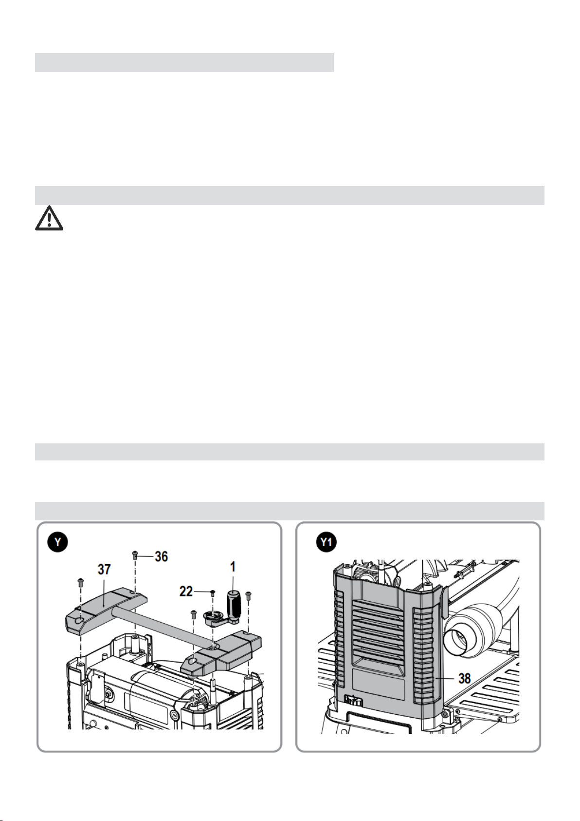
7.6 REPLACE THE TIMING BELT (FIG. Y–Y4)
19
1) Loosen and remove flower pan head screw M6 x 12 (22). Remove the cutter head adjustment handle
(1).
2) Remove four hexagon socket flat head screws (36) from the top panel (37) of the planer.
3) Lift the side panel (38) (located on the cutter head adjustment handle side) up out of the slot in the
base and remove the side panel (38) from the machine.
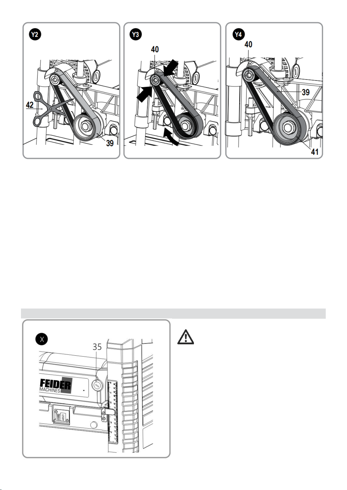
4) Cut off the old timing belt (39) with scissors (42) (not supplied) and remove it.
5) Start a new timing belt (39) on the top pulley (40) with the grooves on the top pulley, as shown in
Fig.Y3.
6) Guide the belt to the lower pulley (41); with grooves engaged on the lower pulley, rotate the lower
pulley clockwise. Keep pressure on the edge of the belt to keep the grooves engaged on the top pulley.
7) Continue pressure on the side of the belt and rotate the lower pulley while hopping the belt further onto
the pulleys.
8) All the belt grooves should be engaged in the final position shown in Fig. Y4 and the pulleys should
rotate smoothly.
9) Replace the belt cover, side panel and top panel. Do not overtighten the screws.
NOTE:
No tools are necessary to install a belt. The use of a screwdriver or other tool to pry or stretch a belt may
cause damage to the pulleys and ultimately destroy the new belt.
7.7 TO REMOVE BRUSH ASSEMBLY (FIG. X)
WARNING: To reduce the risk of serious
personal injury, turn tool off and disconnect tool
from power source before making any adjustments
or removing/installing attachments or accessories.
1) Remove the brush inspection cap (35).
2) Withdraw the brush assembly.
20
Table of contents


