CO/Tech LBC 36 User manual

Ver. 200801
Important information:
Read the instruction manual carefully and
make sure that you understand everything
before you use the product, save it for future
use.
Viktig information:
Läs hela bruksanvisningen noggrant och
försäkra dig om att du har förstått den innan
du använder utrustningen och spara den för
framtida bruk.
Viktig informasjon:
Les disse anvisningene nøye og forsikre deg
om at du forstår dem før du bruker enheten og
oppbevar dem for senere bruk.
Tärkeää tietoa:
Lue nämä ohjeet huolellisesti ja varmista että
olet ymmärtänyt ne, ennen kuin alat käyttää
laitetta. Säilytä ohjeet myöhempää tarvetta
varten.
English 2
Svenska 11
Norsk 20
Suomi 29
No: 30-7803
Model PT 260
Planer & Thicknesser
Rikt- och Planhyvel
Avretter og tykkelseshøvel
Oiko- ja tasohöylä PT

2
English
Planer & Thicknesser, article number: 30-7803,model: PT260
Please read the entire instruction manual before using and save it for future use. We apologise for any text or
photo errors and any changes of technical data. If you have any questions concerning technical problems please
contact our Customer Service Department (see address on reverse.)
Safety
Warning! When using this tool fundamental safety measures must be observed to decrease the risk of re, electric
shock and personal injury. Read all of these instructions before using the product and retain these instructions.
1. Keeptheworkplaceclean.
Cluttered areas and work tables are accidents waiting to happen.
2. Taketheworkingenvironmentintoconsideration.
Do not expose the tools to rain. Do not use the tools in damp or wet spaces. Keep the working area well-lit.
Do not use the tools in the proximity of inammable liquids or gases.
3. Avoidelectricshocks.
Avoid physical contact with earthed objects such as water pipes, radiators, kitchen cookers and fridges.
4. Keepeveryoneatadistance.
Do not let anyone, especially children, who is not participating in the work touch the tool or any of the
extensions. Keep everyone at a distance from the work place.
5. Storethetoolinasafespace.
When the tool is not being used, store it in a dry, locked space out of the reach of children.
6. Donotforcethetool.
It carries out the job more efciently and safely at the intended feed speed.
7. Usethecorrecttool.
Do not force small tools to do big jobs which require powerful tools. Do not force a tool or auxiliary equipment
to carry out work for which it is not designed; e.g. do not use a circular saw to cut down branches or timber.
8. Wearappropriateclothing.
Do not wear any loose clothing or jewellery as they can get caught in rotating parts. When working outdoors,
non-slip shoes are recommended. Wear a hairnet (or similar) if you have long hair.
9. Alwayswearprotectiveequipment.
Wear safety goggles. Use a protective mask if the work creates a lot of dust.
10. Usedustcollectingequipment.
If it is possible to attach a dust collector to the tool, ensure that it is tted and used properly.
11. Donotmanhandlethepowercable.
Instead of tugging at the cable, disconnect it by pulling the plug out of the socket. Ensure that the power cable
does not come into contact with heat, oil or sharp edges.
12. Securetheworkpieceproperly.
When possible, use clamps or a vice to secure the workpiece. That is safer than holding the workpiece with one
hand.
13. Donotoverreach.
Ensure that you stand safely and with good balance at all times.
14. Keepthetoolsinworkingorder.
Ensure that they are clean and that the cutting edges are sharp for an optimal and safe result. Follow the rec-
ommendations in the manual regarding lubrication and change of ttings. Check the power cable regularly. If
it is damaged it should be changed by a qualied service technician. Check all extension cables regularly to
ensure that they are not damaged. Ensure that the handles and controls of the machinery/tools are dry, clean
and completely free from oil, grease etc.
15. Switchthepoweroff.
Pull out the plug and press the emergency stop button before servicing and when changing ttings such as
planer tools, drill bits, tools, abrasive belts or blades.

3
English
16. Removeallkeysandservicetools.
Make a habit of checking that all keys and service tools are removed from the machinery before switching on
the power.
17. Avoidstartingunintentionally.
Do not carry a tool with your nger on the switch/trigger if the cable is plugged into a socket. Ensure that the
switch is in the off position when connecting the plug.
18. Usethecorrectextensioncables.
When using extension cables outdoors, only use those which are intended for outdoor use. Use extension
cables with sufcient conductivity. Uncoil the entire cable.
19. Usecommonsenseandbecareful.
Think twice before carrying out a working operation so that you can carry it out in a safe manner. Do not use
the machinery/tool when you are tired, under the inuence of medication etc.
20. Beforestartingthemachinerycheck:
- That all covers and other parts are undamaged and in working order.
- That all moving parts can rotate freely and are correctly set.
- That no moving parts can jam.
- That no defects have arisen.
- Other circumstances which could inuence the manner in which the work is carried out.
A safety guard or other part that has been damaged must be repaired by a service technician or changed.
Damaged power cables and switches must always be changed by a qualied technician. Never use the tool if
you cannot switch it off or start it in a safe manner.
21. Userecommendedttings.
Using ttings that have not been recommended may cause accidents and personal injury.
22. Mustberepairedbyaqualiedtechnician.
The machinery conforms to current safety requirements. Repairs on the machinery must always be carried
out by a qualied technician using genuine replacement parts. Otherwise the tool may cause accidents or
personal injury.
Specific safety instructions for the planer & thicknesser
• Never use the machine unless the protective covers are undamaged, correctly installed, and adjusted.
• Never use dull plane irons as this will increase the risk of kickback.
• When surface planing, the unused part of the cutter must be covered by the cutter guard.
• When surface planing short workpieces, a push stick should be used.
• The surface plane should not be used when planing grooves, sinks, tenons, or proles.
• The operation of the anti-kickback mechanism and the feed rollers should be checked regularly to assure safe
operation.
• Whether surface planing or thicknesing, a dust extractor should be attached to the plane.
Product labelling
Read the entire operations manual.
Always use protective goggles or a visor and a dust mask.
Always use ear protection.

4
English
2. Assembly
2.1 Attach the legs to the body secure them with hexagon bolt
M8 x 16, spring washer B8, and hexagon nut M8.
2.2 Attach the rubber pads to the legs.
2.3 Attach the dust extractor by using the four plate screws
(included).
2.4 Detach the fastening splints for the feed table for thickness
planing, assemble the table, and secure it with the splints.
2.5 Add the output table and attach it with the two locking arms.
2.6 Attach the fence attachment to the feed table with 2 M8
hexagon screws.
Pull the lever outwards to
allow it to swing right or
left.
2.7 Push the screw heads into the groove of the fence and attach it to the segment with the two self-locking
nuts M6. Then attach the cover plate to the fence attachment with 2 M4x8 screws with cylinder heads and
washers.
2.3 2.4 2.5
2.1
2.6
2.7 2.7

5
English
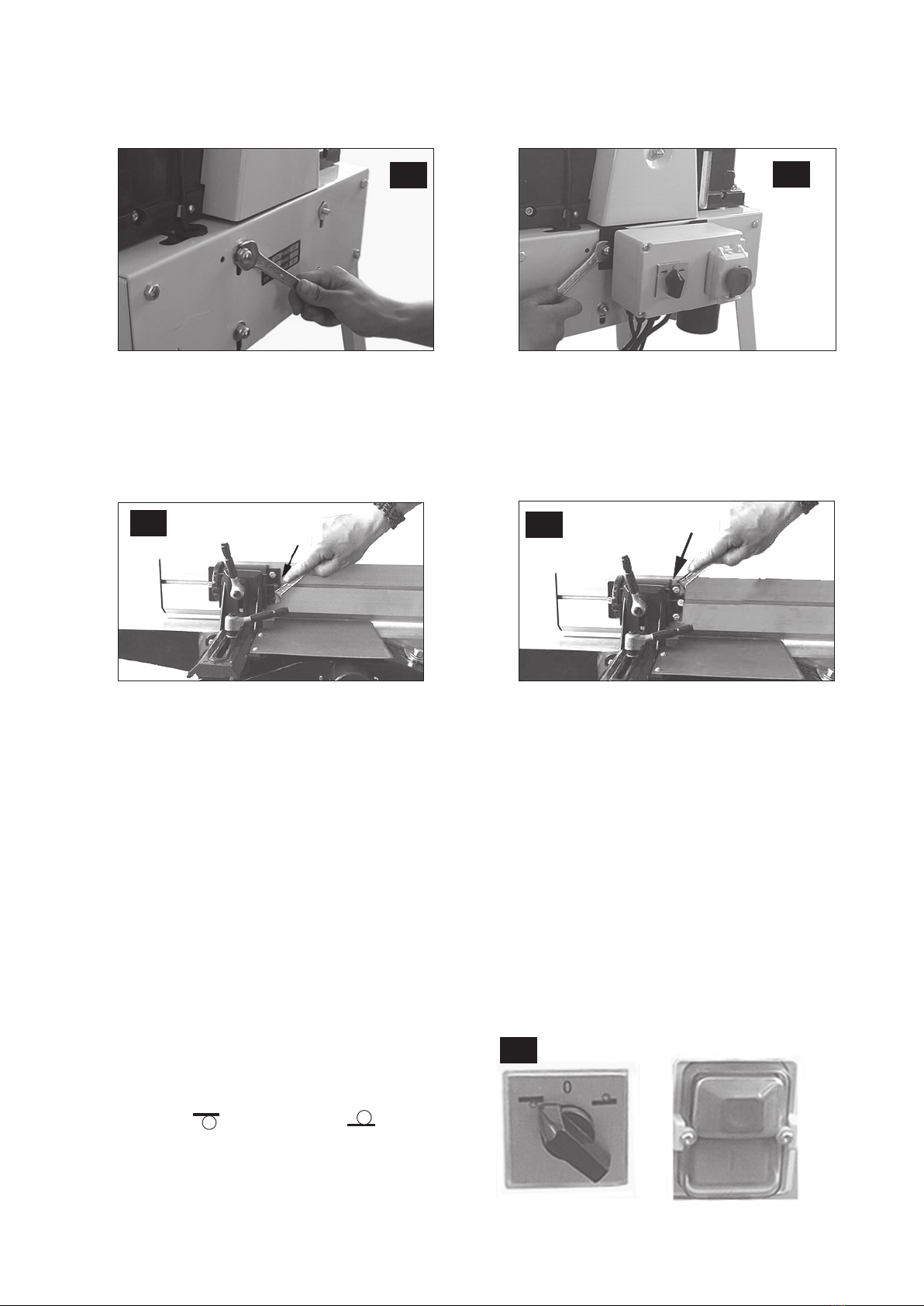
2.8 Disassemble the two upper dome nuts and washers. Attach the locking bolt of the power switch to the
screws. Attach the washers and tighten the dome nuts.
3. Adjustment of the fence
Turn the setscrews of the fence in and out as needed to achieve the exact segment stop of 45° and 90°.
Note:Lubricateallslidingareas.
4. Electrical connection
• Double-check that the voltage agrees with that indicated on the label on the motor rating plate.
• Connect the machine to an earthed wall socket through an earthed extension cord.
5. Power switch
All power switches have zero voltage tripping to prevent the plane from starting after a power outage.
Please note:
• There are two power switches on the panel.
• The one on the right is the main switch with zero
voltage tripping.
• The one on the left is the program lever to change
between surface and thickness planning .
• For your safety, always set the lever to “0” when the
machine is not in use.
2.8 2.8
3.0 3.0
5.1

6
English
6. Dust extraction
The package includes a sleeve coupling connectable to a diame-
ter of 100 mm. Always use some form of dust extraction when
planing.
7. Surface planing
The following measures must be taken before level planing.
7.1 Set the program lever to surface planing .
7.2 Set the thickness planer table to approximately 2/3 of its
full capacity and attach the dust hood. Raise the table and
lock the hood. Make sure that the socket on top of the dust
hood locks against the spindle above.
NOTE:Unless the dust hood is installed, the safety switch
will not work and the machine will not start.
7.3 Make sure that the surface planer table, which can be dis-
assembled, is locked so that the safety breaker is free to
operate.
NOTE: Unless the locking arms are in the right position,
the plane will not start.
If the machine still does not start, please contact our Cus-
tomer Service Department.
7.4 Adjust the height with the lever to the left of the plane.
After lifting the locking lever, you can adjust the cutterguard
sideways to the correct gap for the workpiece when surface
planing. Lower the locking lever to lock the cutterguard in
position. Push the workpiece against the feed table and set
the cutter guard to the height of your left hand. (The work-
piece should barely t through the gap.) Start the motor
and slowly and steadily feed the workpiece across the cut-
ter. Let your hands glide across the cutter guard.
7.5 When level planing edges, start by loosening the locking
lever to the cutter guard and setting the gap to the width of
the workpiece. The springing plastic piece at the right edge
of the guard should be lightly pressed to the workpiece.
Lock the guard in position and start the motor.
Feed the workpiece slowly and steadily across the cutter.
Make sure the fence is at a 90° angle exactly (or other
angle desired) to the output table and push the workpiece
to the fence and downward during feeding.
7.3
7.4 7.4
7.5
7.1
7.2

7
English
8. Thickness planing
The following measures should be taken before thickness
planing.
8.1 Set the program lever to thickness planing .
8.2 Wind the surface planer height adjustment crack handle
anticlockwise and remove the dust hood.
8.3 Fold out the locking arms for the surface planing table and
remove the table. Pull the cutter cover outside the table
and set it to its top position.
8.4 Turn in the output hood across the cutter and attach the
dust hood. Lock it with the cutter cover. The dust hood
acts as a cutter cover when thickness planing.
NOTE:Neveroperatethemachineunlessthedust
hoodisinstalledandlocked.
A circuit breaker prevents start with an improperly installed
dust hood.
8.5 Change the setting of the machine to thickness planing
as described above. Set the thickness planing table to the
desired thickness of the workpiece.
Maximumcuttingthickness:3mm.(NOTE:Measure
atbothendsoftheworkpiece.)
Start the machine and feed in the workpiece with the
planed surface facing downwards and push slowly until
the feed rolls grip If the workpiece is wedge-shaped, feed
in the thickest end rst.
8.2
8.3
8.4
8.4
8.4

8
English
9. Replacing/adjusting disposable cutter irons
Note:Unplugthedevicebeforeservice.
Remove the fence. Loosen the hexagon screws on the locking wedge (pushing the cutter iron against the cut-
ter) with the included 10 mm spanner by turning these clockwise inwards. Remove the cutter iron and the locking
wedge from the groove of the cutter. Clean the wedge, groove, and cutter iron of debris, shavings, and dust with
an oily cloth.
Turn the cutter iron or replace it. Reinstall the iron and wedge back in the groove and lock them in position by
turning the screws anticlockwise (but turn only slightly so that they do not fall out.) Check how far the cutter iron
protrudes above the output table by laying a ruler on the output table or by using a setting guage.
Maximumprotrusionabovetheoutputtable:0.1mm.Repeatwiththeothercutteriron.
Adjust the cutter protrusion using the included 3 mm allen key by turning the wedge`s three setscrews in and
out as desired. After achieving the correct setting, tighten the hexagon screws again. Start with the screw in the
middle.
Note:Donotusea10mmspannerwithashaftlongerthanthatwhichisincludedtoavoidtheriskof
damagingthegrooves.Immediatelyreplacealockingwedgehavingwithdamagedgrooves.
3 mm allen key
Setting guage
9.0 9.0

9
English
10. Drive belt tension
Check the drive belt tension after the rst ve machine hours.
Remove the dome nut holding the belt cover (215) in place.
Check the tension by pushing the belt as illustrated. It should be
possible to push the belt about 15 – 20 mm.
11. Maintenance
Regularly clean the feed gears of the thicknessing plane with a
brush or compressed air. Regularly lubricate all grease areas
and chains with a few drops of motor oil. Make sure that no oil
or other greasing agent comes in contact with the driving belt
of the gears.
11.1 Regularly clean the thicknessing plane tables spindles and
lubricate them with an oil spray, such as WD 40. Do not
use regular motor oil.
11.2 Assure that the feed and output tables, plus the surface
plane table, are free of resins. Clean them regularly, and
then wax them with a suitable lubricant spray so that the
workpieces will glide easily.
12. Responsibility of the user
This machine functions according to the description in this operations manual if installed, used, maintained, and
repaired in accordance with the instructions herein.
The machine must be checked regularly. Defective equipment (including connecting cables) must not be used.
Defective, missing, worn, deformed, or otherwise damaged parts must be replaced immediately.
If such repairs or replacements are necessary, we recommend the use of a qualied technician.
The machine, or the parts of the machine, should not be modied. The user of the machine has the sole respon-
sibility for any faulty functions that may be caused by violations of the instructions for use, unauthorized modica-
tions, faulty maintenance, damages, or faulty repairs.
13.Disposal
Follow local ordinances when disposing of this product. If you are unsure about how to dispose of this
product contact your municipality.
10.0
11.0
11.1

10
English
14. Technical data
Table surface, surface plane: 260 x 1000 mm
Table surface, thickness plane: 250 x 400 mm
Max. planing width: 260 mm
Max. height, thickness planing: 155 mm
Max. chip size: 3 mm
Cutter diameter: 63 mm
Planing irons: 2 pairs
Cutter revolutions: 6500 RPM
Feed (surface plane): 5 m/min
Motor revolutions: 2800 RPM
Max. angle of the fence: 45°
Table height: 860 mm
Weight: 60 kg
Noise level: 75.7 dB (A) unloaded, 90.3 dB (A) loaded
Motor: 2.2 kW/3hp, 230V, 50Hz

11
Svenska
Rikt & planhyvel, artikelnummer 30-7803, model: PT260
Läs igenom hela bruksanvisningen före användning och spara den sedan för framtida bruk.
Vi reserverar oss för ev. text- och bildfel samt ändringar av tekniska data.
Vid tekniska problem eller andra frågor, kontakta vår kundtjänst (se adressuppgifter på baksidan).
1. Säkerhet
Varning!När du använder detta verktyg ska grundläggande försiktighetsåtgärder iakttas för att minska risken för brand,
elektrisk chock och personskada. Läs alla dessa instruktioner innan du använder produkten och spara dessa instruktioner.
1. Hållarbetsplatsenren.
Belamrade ytor och bord inbjuder till olyckor.
2. Taghänsyntillarbetsmiljön.
Utsätt inte verktygen för regn. Använd inte verktygen i fuktiga eller våta utrymmen. Håll arbetsplatsen väl upplyst.
Använd inte verktygen i närheten av lättantändliga vätskor eller gaser.
3. Undvikelektriskchock.
Undvik kroppskontakt med jordade föremål som t.ex. vattenledningar, element, köksspisar och kylskåp.
4. Hållandramänniskorpåavstånd.
Låt inga människor, speciellt inte barn, som inte deltar i arbetet röra vid verktyget eller dess skarvsladdar. Håll dem
på avstånd från arbetsplatsen.
5. Förvaraverktygetiettsäkertutrymme.
När verktygen inte används, förvara dem i ett torrt låst utrymme utom räckhåll för barn.
6. Överbelastainteverktyget.
Det gör jobbet bättre och säkrare med avsedd matningshastighet.
7. Användrättverktyg.
Pressa inte små verktyg att utföra stora jobb som kräver kraftfulla verktyg. Pressa inte ett verktyg eller en tillsats att
göra ett arbetsmoment som den inte är gjord för; använd t.ex. inte en cirkelsåg för att kapa trädgrenar eller timmer.
8. Bärlämpligklädsel.
Bär inga löst sittande kläder eller smycken, de kan fastna i roterande delar. Halksäkra skor rekommenderas vid
arbete utomhus. Bär hårnät eller liknande om du har långt hår.
9. Bäralltidskyddsutrustning.
Bär skyddsglasögon. Använd också dammlter eller skyddsmask vid dammande arbeten.
10.Användutsugningsutrustning.
Om verktyget är förberett för anslutning av utrustning för utsugning och uppsamling av damm, se till att utrustningen
är ansluten och korrekt använd.
11.Misshandlaintenätsladden.
Ryck inte i sladden, utan dra i stickproppen när du ska ta ur den ur vägguttaget. Se till att nätsladden inte kommer i
kontakt med värme, olja eller vassa kanter.
12.Spännfastarbetsstycketordentligt.
När det är möjligt, använd tvingar eller skruvstäd för att spänna fast arbetsstycket. Det är säkrare än att hålla fast
arbetsstycket med ena handen.
13.Sträckdiginteförlångt.
Se till att du hela tiden står säkert med god balans.
14.Hållverktygenitrim.
Se till att de är rena och eggarna vassa för optimal effekt och ett säkert resultat. Följ manualens rekommendationer
för smörjning och byte av tillbehör. Kontrollera nätsladden regelbundet. Om den är skadad ska den bytas av en
kvalicerad servicetekniker. Syna alla skarvsladdar regelbundet så att de inte är skadade. Se till att maskinens/
verktygets handtag och reglage är torra, rena och helt fria från olja, fett etc.
15.Slåavströmmen.
Dra ur stickproppen och tryck in nödstopp före service och vid byte av tillbehör som hyvelstål, borrar, stål, slipband
eller blad.

12
Svenska
16.Tabortallanycklarochserviceverktyg.
Gör det till en vana att kontrollera att alla nycklar och serviceverktyg är borttagna från maskinen innan du slår på
strömmen.
17.Undvikoavsiktligstart.
Bär inte ett verktyg med ett nger på strömbrytaren/avtryckaren om sladden sitter i ett uttag. Se till att strömbrytaren
står på OFF när du sätter in stickproppen.
18.Användrättskarvsladdar.
Om du använder skarvsladdar utomhus, använd endast de som är avsedda för utomhusbruk. Använd skarvsladdar
med tillräcklig ledararea och rulla ut hela sladden.
19.Användsuntförnuftochvarförsiktig.
Tänk efter innan du utför ett arbetsmoment, så att du kan utföra det på ett säkert sätt. Använd inte maskinen/
verktyget när du är trött, påverkad av mediciner etc.
20.Kontrolleraföljandeinnandustartarverktyget:
- Att alla skydd och övriga delar är oskadade och fyller sin funktion.
- Att rörliga delar kan rotera fritt och är rätt inriktade.
- Att inga rörliga delar kan fastna.
- Att ingen defekt har uppstått.
- Andra omständigheter som kan påverka arbetets utförande.
Ett skydd eller någon annan del som skadats, skall repareras fackmässigt eller bytas ut. Skadade nätsladdar och
strömbrytare ska alltid bytas ut av fackman. Använd aldrig verktyget om du inte kan stänga av eller starta det på ett
betryggande sätt.
21.Användrekommenderadetillbehör.
Användning av ej rekommenderade tillbehör kan vålla olyckor eller risk för personskada.
22.Reparerasendastavkvaliceradtekniker.
Verktyget överensstämmer med gällande säkerhetskrav. Reparationer av verktyget ska alltid utföras av fackman,
med originalreservdelar, annars kan verktyget vålla olyckor eller risk för personskada.
Särskilda säkerhetsinstruktioner för rikt- och planhyvel
• Använd aldrig maskinen utan att skydden är hela och på plats samt injusterade.
• Använd aldrig hyvelstål som är slöa då detta ökar risken för bakslag.
• Vid rikthyvling måste den del av kuttern som inte används täckas av kutterskyddet.
• Vid rikthyvling av korta arbetsstycken skall en påskjutare användas.
• Rikthyveln skall inte användas för hyvling av falsar, sinkar, slitstappar eller proler.
• Funktionen hos bakslagspärren och matarvalsarna skall kontrolleras med jämna mellanrum för att säkerställa
säker användning.
• Vid rikt eller planhyvling skall en spånsug anslutas till spånhyven.
Produktmärkning
Läs hela bruksanvisningen!
Använd alltid skyddsglasögon eller visir och andningsskydd.
Använd alltid hörselskydd.

13
Svenska
2. Slutmontering
2.1 Sätt dit benen mot chassiet och skruva fast dem
med sexkantskruv M8 x 16, fjäderbricka B8 och
sexkantmutter M8.
2.2 Skjut på gummitassarna på benändarna.
2.3 Skruva fast spånutkastet med de fyra
medlevererade plåtskruvarna.
2.4 Skruva loss fästskenorna för inmatningsbordet för planhyvling,
montera bordet och skruva fast det med skenorna.
2.5 Lägg på utmatningsbordet och lås det med de två
låsarmarna.
2.3 2.4 2.5
2.1
2.6 Skruva fast anhållsfästet i inmatningsbordet
med 2 st. M8 sexkantskruvar.
Dra spaken utåt.
Då kan den svängas
åt höger eller vänster.
2.7 Skjut in skruvskallarna i spåret på anhållet och sätt fast det i segmentet med de två självlåsande
muttrarna M6. Sätt sedan fast täckplåten på anhållsfästet med 2 st. M4x8 skruvar med cylinderskalle samt
brickor.
2.6
2.7 2.7
14
Svenska
3. Inställning av anhåll
Vrid ställskruvarna på anhållet in och ut efter behov för exakt segmentstopp på 45° och 90°.
Obs!Smörjallaglidytor.
3.0 3.0
4. Elanslutning
• Kontrollera att nätspänningen stämmer överens med angiven märkspänning på motorns märkplåt.
• Anslut maskinen med en jordad skarvsladd till ett jordat vägguttag.
5. Strömbrytare
Alla strömbrytare har nollspänningsutlösning för att hindra att hyveln går igång efter strömavbrott.
5.1
2.8 Demontera de båda övre kupolmuttrarna och brickorna. Sätt fast strömbrytarens fästbygel på skruvarna.
Montera brickorna och dra fast kupolmuttrarna.
2.8 2.8
Viktig anvisning!
• Det nns två strömbrytare på panelen.
• Den högra är huvudbrytaren med O-
spänningsutlösare.
• Den vänstra är lägesbrytare för att växla mellan
rikthyvling och planhyvling .
• För er egen säkerhet ställ alltid brytaren i ”O” läge
när maskinen inte används.

15
Svenska
6. Spånsugning
I leveransen ingår en stos med anslutning för 100 mm diameter.
Använd alltid någon form av spånsug vid hyvling.
7. Rikthyvling
Följande måste utföras före rikthyvling.
7.1 Ställ lägesbrytaren i rikthyvlingsläge .
7.2 Ställ in planhyvlingsbordet på ca 2/3 av max. kapacitet och
stoppa in spånhuven. Veva upp bordet och lås huven.
Se till att uttaget på ovansidan av spånhuven
låser mot spindeln ovanför.
OBS!Om spånhuven inte monteras fungerar
inte säkerhetsbrytaren och maskinen startar inte.
7.3 Se till att det demonterbara rikthyvlingsbordet är låst
så att säkerhetsbrytaren frikopplas.
OBS!Omintelåsarmarnaärirättpositionstartarinte
hyveln.
Om maskinen ändå inte startar kontakta vår kundservice.
7.4 Du ställer in höjden med spaken på hyvelns vänstra sida.
När du lyft låsspaken kan du ställa in skyddet i sidled med
lagom brett gap för brädan vid rikthyvling. Sänk låsspaken
för att låsa skyddet i läge.
Tryck brädan mot inmatningsbordet och ställ in kutter-
skyddet i höjd med vänster hand (brädan ska nätt och jämnt
kunna gå igenom gapet). Starta motorn och mata sakta och
stadigt igenom brädan över kuttern. Låt händerna glida över
kutterskyddet.
7.5 Vid rikthyvling av kanter börjar du med att lossa låsspaken
för kutterskyddet och ställa in gapet efter brädans tjocklek.
Den fjädrande plastbiten på skyddets högerkant bör trycka
lätt mot brädan. Lås skyddet i läge och starta motorn.
För brädan långsamt och stadigt över kuttern. Se till att
anhållet står i exakt 90° vinkel (eller annat önskat gradtal)
mot utmatningsbordet och tryck brädan mot anhållet och
neråt vid matningen.
7.3
7.4 7.4
7.5
7.1
7.2

16
Svenska
8. Planhyvling
Följande måste utföras före planhyvling.
8.1 Ställ lägesbrytaren i planhyvlingsläge .
8.2 Vrid inställningsratten för rikthyvlingsbordet moturs och tag
ut spånhuven.
8.3 Fäll ut låsarmarna för rikthyvlingsbordet och tag bort
bordet. Dra ut kutterskyddet utanför bordet och ställ det i
toppläge.
8.4 Sväng in utkasthuven över kuttern och sätt på spånhuven.
Lås med kutterskyddet. Spånhuven fungerar som
kutterskydd vid planhyvling.
OBS!Arbetaaldrigmedmaskinenutanmonteradoch
låstspånhuv.
Skyddsbrytare förhindrar start vi felaktigt monterad
utkasthuv.
8.5 Ställ om maskinen för planhyvling enligt ovan. Ställ in
planhyvlingsbordet till önskad materialtjocklek.
Max.avverkning3mm.(OBS!Mätibådaändarnaav
arbetsstycket).
Starta maskinen och mata in arbetsstycket med den
hyvlade ytan nedåt och skjut sakta på tills att matarrullarna
greppar tag. Om arbetsstycket är kilformat, mata in den
tjockaste änden först.
8.2
8.3
8.4
8.4
8.4

17
Svenska
Justera utsticket med medföljande 3 mm insexnyckel genom att vrida kilens tre ställskruvar ut och in efter önskan.
Efter korrekt inställning drar du åt sexkantskruvarna igen. Börja med skruven i mitten.
Obs!Användinteen10mmnyckelmedlängreskaftändensommedföljerförattundvikaattdrasönder
gängorna.Bytgenastutenlåskilmedförstördgänga.
9. Byte/Inställning av engångs kutterstål
Obs!Draurstickproppenuruttagetföreservice!
Ta bort anhållet. Lossa sexkantskruvarna på låskilen (som trycker kutterstålet mot kuttern) med medföljande 10
mm fast nyckel genom att vrida dem medsols inåt. Ta ut kutterstål och kilen ur spåret på kuttern. Rengör kil, spår
och kutterstål från skräp, spån och damm med en oljad trasa. Vänd kutterstålet eller byt ut det. Sätt in stål och kil
i spåret igen och lås dem i läge genom att vrida skruvarna motsols(mendrabaralitesåattdeintefallerur).
Kontrollera hur mycket kutterstålet sticker ut ovanför utmatningsbordet med mall eller linjal på utmatningsbordet.
Max.utsticköverutmatningsbordet:0,1mm.Görpåsammasättmeddetandrakutterstålet.
3 mm insexnyckel
Mall
9.0 9.0

18
Svenska
10. Remspänning
Kontrollera drivremmens spänning efter de fem första drifttim-
marna.Ta bort kupolmuttern som håller fast remkåpan (215).
Kontrollera spänningen genom att trycka mot remmen som
bilden visar. Remmen bör kunna tryckas ca 15 - 20 mm.
11. Vård
Rengör regelbundet planhyvlingens matarväxel med borste
eller tryckluft. Smörj regelbundet alla smörjställen och kedjor
med några droppar motorolja. Se till att det inte kommer någon
olja eller annat smörjmedel på växelns drivrem.
11.1 Rengör regelbundet planhyvlingsbordets gängspindlar
och smörj dem med oljesprej (t. ex. WD 40). Använd inte
vanlig motorolja.
11.2 Se till att in- och utmatningsborden samt
planhyvlingsbordet är fria från harts och kåda. Rengör
dem regelbundet och vaxa sedan in dem med lämplig
glidsprej så att ämnena glider bättre.
10.0
11.0
11.1
12. Användarens ansvar
Den här maskinen fungerar i enlighet med beskrivningen i denna instruktion om den installeras, används, under-
hålls och repareras enligt bifogade instruktioner.
Maskinen måste kontrolleras regelbundet. Defekt utrustning (inklusive anslutningskabel) får inte användas. Delar
som är trasiga, saknas, utslitna, deformerade eller på annat sätt skadade måste bytas ut omedelbart. Skulle så-
dan reparation eller utbyte bli nödvändigt, rekommenderas att det utförs av kvalicerad tekniker.
Maskinen eller maskinens delar får inte ändras från det ursprungliga utförandet. Användaren av maskinen har
ensam ansvaret för alla eventuella felfunktioner som kan förorsakas av felaktig användning, ej auktoriserade
modieringar, felaktigt underhåll, skador eller felaktiga reparationer.
13. Avfallshantering
När du ska göra dig av med produkten ska detta ske enligt lokala föreskrifter. Är du osäker på hur du
ska gå tillväga, kontakta din kommun.

19
Svenska
14. Tekniska data
Bordsyta, rikthyvel: 260 x 1000 mm
Bordsyta, planhyvel: 250 x 400 mm
Max. hyvlingsbredd: 260 mm
Max. tjocklek, planhyvling: 155 mm
Max. spåntjocklek: 3 mm
Kutter diameter: 63 mm
Kutterstål: 2 par
Kuttervarvtal: 6500 v/min
Matning (planh.): 5 m/min
Motorvarvtal: 2800 v/min
Max. lutning av anhåll: 45°
Bordshöjd: 860 mm
Vikt: 60 kg
Ljudnivå: 75,7 dB (A) obelastad, 90,3 dB (A) belastad
Motor: 2,2 kW/3hk, 230V, 50Hz

20
Norsk
Avretter og tykkelseshøvel, artikkelnummer 30-7803, modell: PT260
Les nøye igjennom hele bruksanvisningen og ta vare på den til senere bruk.
Vi reserverer oss mot ev. tekst- og bildefeil, samt forandringer av tekniske data.
Ved tekniske problemer eller andre spørsmål, ta kontakt med vårt kundesenter (se opplysninger på baksiden).
1. Sikkerhet
1. Holdarbeidsstedetryddig!
Uryddige arbeidsplasser innbyr til ulykker.
2. Brukikkemaskinenirisikofyltmiljø!
Elektromaskiner skal ikke benyttes i fuktige, våte miljøer eller ved regn. Påse at belysningen er god på arbeidsstedet.
Sørg for god luftsirkulasjon ved støvfylte oppgaver. Bruk aldri elektriske maskiner/verktøy der de kan forårsake brann
eller eksplosjon!
3. Unngåelektrisksjokk!
Unngå kroppskontakt med jordede formål som vannledning, element, komfyr etc. samtidig som du bruker
elektromaskiner/verktøy.
4. Holdbarnogtilskuerepåavstand!
Barn og tilskuere bør benne seg på sikkerhetsavstand fra elektromaskiner/verktøy eller elkabler på arbeidsstedet.
5. Barnesikkeroppbevaring!
Oppbevar elektromaskiner/verktøy innelåst eller utenfor rekkevidde for barn når de ikke er i bruk.
6. Pressikkemaskinen!
Maskinen gjør jobben bedre og sikrere med beregnet matehastighet.
7. Brukriktigverktøy!
Press ikke et verktøy eller lignende til å utføre et arbeidsmoment den ikke er beregnet for.
8. Brukegnetkledsel!
Bruk ikke løstsittende klær, vanter, hals-/armbånd, ringer eller andre smykker som kan sette seg fast i roterende
deler. Sklisikre sko anbefales. Bruk hårnett eller tilsvarende om du har langt hår.
9. Brukverneutstyr!
Benytt alltid vernebrille, vanlige briller duger ikke! Bruk også støv-/vernemaske samt hørselvern der dette kreves.
10.Utlufting!
Bruk tilgjengelig utsugingsutrustning for å fjerne og samle opp støv og spon. Om maskinen er beregnet for det, påse
at utrustningen brukes på riktig måte og tømmes ved behov.
11.Beskadigeikkenettkabelen!
Bær aldri maskinen i nettkabelen. Rykk ikke i kabelen, men trekk i støpselet når strømmen brytes. Påse at kabelen ikke
kommer i kontakt med varme, olje eller skarpe kanter.
12.Settfastemnetordentlig!
Bruk tvinger eller skruestikke der dette er mulig, du kan da håndtere verktøyet med begge hender. Dette er sikrere
enn å holde emnet med en hånd.
13.Strekkdegikkeforlangt!
Sørg for at du hele tiden står stødig og med god balanse.
14.Holdverktøyetigodstand!
Se etter at eggen er hvass for optimal effekt og sikkert resultat. Følg manualens anbefalinger for smøring og bytte
av tilbehør. Kontrollér nettkabelen regelmessig, om den er skadet skal den byttes av en kyndig person. Dette gjelder
også ved bruk av skjøteledninger. Maskinens håndtak, strømbryter m.m. skal være rene, tørre og fri for olje, fett etc.
15.Slåavstrømmen!
Trekk ut støpselet og trykk inn nødstopp innen service utføres eller ved bytte av tilbehør som høvelstål, bor,
slipebånd, blad etc.
16.Tabortallenøklerogserviceverktøy!
Gjør det til en vane å kontrollere at alle nøkler og serviceverktøy er fjernet fra maskinen før du slår på strømmen.
Other manuals for LBC 36
3
Table of contents
Languages:
Other CO/Tech Planer manuals


