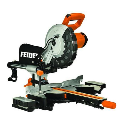
Feider Machines FSOR17210 User manual

ORIGINAL INSTRUCTIONS >EN
MITRE SAW
FSOR17210
USER GUIDE
CAUTION: Read the instructions before using the machine!

CONTENTS
1. SAFETY INSTRUCTIONS ............................................................................3
2. TECHNICAL DATA........................................................................................9
3. PRODUCT DESCRIPTION (FIG.1-22)........................................................11
4. SCOPE OF DELIVERY ...............................................................................14
5. INTENDED USE..........................................................................................14
6. BEFORE STARTING THE EQUIPMENT ...................................................15
7. ATTACHMENT AND OPERATION.............................................................16
8. TRANSPORT (FIG.1,2)..............................................................................20
9. MAINTENANCE..........................................................................................21
10. STORAGE.................................................................................................21
11. ELECTRICAL CONNECTION ..................................................................22
12. DISPOSAL ANDRECYCLING .................................................................23
13. TROUBLESHOOTING..............................................................................24
14. DECLARATION OF CONFORMITY.........................................................25
15. WARRANTY..............................................................................................26
16. PRODUCT FAILURE ................................................................................27
17. WARRANTY EXCLUSIONS.....................................................................28
CAUTION: Read the instructions before using the machine!

3
1. SAFETY INSTRUCTIONS
1.1 GENERAL POWER TOOL SAFETY WARNINGS
WARNING Read all safety warnings, instructions, illustrations and specifications provided with
this power tool. Failure to follow all instructions listed below may result in electric shock, fire and/or
serious injury.
Save all warnings and instructions for future reference.
The term "power tool" in the warnings refers to your mains-operated (corded) power tool or battery-
operated (cordless) power tool.
1) Work area safety
a) Keep work area clean and well lit. Cluttered or dark areas invite accidents.
b) Do not operate power tools in explosive atmospheres, such as in the presence of
flammable liquids, gases or dust. Power tools createsparks which may ignite the dust orfumes.
c) Keep children and bystanders away while operating a power tool. Distractions can cause
you to lose control.
2) Electrical safety
a) Power tool plugs must match the outlet. Never modify the plug in any way. Do not use any
adapter plugs with earthed (grounded) power tools. Unmodified plugs and matching outlets will
reduce risk of electric shock.
b) Avoid body contact with earthed or grounded surfaces, such as pipes, radiators, ranges
and refrigerators. There is an increased risk of electric shock if your body is earthed orgrounded.
c) Do not expose power tools to rain or wet conditions. Water entering a power tool will
increase the risk of electric shock.
d) Do not abuse the cord. Never use the cord for carrying, pulling or unplugging the power
tool. Keep cord away from heat, oil, sharp edges or moving parts. Damaged or entangled cords
increase the risk of electric shock.
e) When operating a power tool outdoors, use an extension cord suitable for outdoor use.
Use of a cord suitable for outdoor use reduces the risk of electricshock.
f) If operating a power tool in a damp location is unavoidable, use a residual current device
(RCD) protected supply. Use of an RCD reduces the risk of electric shock.
3) Personal safety
a) Stay alert, watch what you are doing and use common sense when operating a power tool.
Do not use a power tool while you are tired or under the influence of drugs, alcohol or
medication. A moment of inattention while operating power tools may result in serious personal
injury.
b) Use personal protective equipment. Always wear eye protection. Protective equipment such
as a dust mask, non-skid safety shoes, hard hat or hearing protection used for appropriate
conditions will reduce personal injuries.
c) Prevent unintentional starting. Ensure the switch is in the off-position before connecting
to power source and/or battery pack, picking up or carrying the tool. Carrying power tools with
your finger on the switch or energising power tools that have the switch on invites accidents.

4
d) Remove any adjusting key or wrench before turning the power tool on. A wrench or a key
left attached to a rotating part of the power tool may result in personal injury.
e) Do not overreach. Keep proper footing and balance at all times. This enables better control
of the power tool in unexpected situations.
f) Dress properly. Do not wear loose clothing or jewellery. Keep your hair and clothing away
from moving parts. Loose clothes, jewellery or long hair can be caught in movingparts.
g) If devices are provided for the connection of dust extraction and collection facilities,
ensure these are connected and properly used. Use of dust collection can reduce dust-related
hazards.
h) Do not let familiarity gained from frequent use of tools allow you to become complacent
and ignore tool safety principles. A careless action can cause severe injury within a fraction of a
second.
4) Power tool use and care
a) Do not force the power tool. Use the correct power tool for your application. The correct
power tool will do the job better and safer at the rate for which it was designed.
b) Do not use the power tool if the switch does not turn it on and off. Any power tool that
cannot be controlled with the switch is dangerous and must berepaired.
c) Disconnect the plug from the power source and/or remove the battery pack, if detachable,
from the power tool before making any adjustments, changing accessories, or storing power
tools. Such preventive safety measures reduce the risk of starting the power toolaccidentally.
d) Store idle power tools out of the reach of children and do not allow persons unfamiliar
with the power tool or these instructions to operate the power tool.
Power tools are dangerous in the hands of untrained users.
e) Maintain power tools and accessories. Check for misalignment or binding of moving parts,
breakage of parts and any other condition that may affect the power tool’s operation. If
damaged, have the power tool repaired before use. Many accidents are caused by poorly
maintained power tools.
f) Keep cutting tools sharp and clean. Properly maintained cutting tools with sharp cutting edges
are less likely to bind and are easier to control.
g) Use the power tool, accessories and tool bits etc. in accordance with these instructions,
taking into account the working conditions and the work to be performed. Use of the power
tool for operations different from those intended could result in a hazardous situation.
h) Keep handles and grasping surfaces dry, clean and free from oil and grease. Slippery
handles and grasping surfaces do not allow for safe handling and control of the tool in unexpected
situations.
5) Service
a) Have your power tool serviced by a qualified repair person using only identical
replacement parts. This will ensure that the safety of the power tool is maintained.
1.2 SAFETY INSTRUCTIONS FOR MITRE SAWS
a) Mitre saws are intended to cut wood or wood-like products, they cannot be used with
abrasive cut-off wheels for cutting ferrous material such as bars, rods, studs, etc. Abrasive
dust causes moving parts such as the lower guard to jam. Sparks from abrasive cutting will burn the
lower guard, the kerf insert and other plastic parts.

5
b) Use clamps to support the workpiece whenever possible. If supporting the workpiece by
hand, you must always keep your hand at least 100 mm from either side of the saw blade. Do
not use this saw to cut pieces that are too small to be securely clamped or held by hand. If
your hand is placed too close to the saw blade, there is an increased risk of injury from bladecontact.
c) The workpiece must be stationary and clamped or held against both the fence and the
table. Do not feed the workpiece into the blade or cut “freehand” in any way. Unrestrained or
moving workpieces could be thrown at high speeds, causing injury.
d) Push the saw through the workpiece. Do not pull the saw through the workpiece. To make
a cut, raise the saw head and pull it out over the workpiece without cutting, start the motor,
press the saw head down and push the saw through the workpiece. Cutting on the pull stroke is
likely to cause the saw blade to climb on top of the workpiece and violently throw the blade
assembly towards the operator.
NOTE The above warning is omitted for a simple pivoting arm mitre saw.
e) Never cross your hand over the intended line of cutting either in front or behind the saw
blade. Supporting the workpiece “cross handed” i.e. holding the workpiece to the right of the saw
blade with your left hand or vice versa is very dangerous.
f) Do not reach behind the fence with either hand closer than 100 mm from either side of the
saw blade, to remove wood scraps, or for any other reason while the blade is spinning. The
proximity of the spinning saw blade to your hand may not be obvious and you may be seriously
injured.
g) Inspect your workpiece before cutting. If the workpiece is bowed or warped, clamp it with
the outside bowed face toward the fence. Always make certain that there is no gap between
the workpiece, fence and table along the line of the cut. Bent or warped workpieces can twist
or shift
and may cause binding on the spinning saw blade while cutting. There should be no nails or foreign
objects in the workpiece.
h) Do not use the saw until the table is clear of all tools, wood scraps, etc., except for the
workpiece. Small debris or loose pieces of wood or other objects that contact the revolving blade
can be thrown with high speed.
i) Cut only one workpiece at a time. Stacked multiple workpieces cannot be adequately clamped
or braced and may bind on the blade or shift duringcutting.
j) Ensure the mitre saw is mounted or placed on a level, firm work surface before use. A level
and firm work surface reduces the risk of the mitre saw becomingunstable.
k) Plan your work. Every time you change the bevel or mitre angle setting, make sure the
adjustable fence is set correctly to support the workpiece and will not interfere with the blade
or the guarding system. Without turning the tool “ON” and with no workpiece on the table, move
the saw blade through a complete simulated cut to assure there will be no interference or danger of
cutting the fence.
NOTE The phrase “bevel or” does not apply for saws without bevel adjustment.
l) Provide adequate support such as table extensions, saw horses, etc. for a workpiece that
is wider or longer than the table top. Workpieces longer or wider than the mitre saw table can tip
if not securely supported. If the cut-off piece or workpiece tips, it can lift the lower guard or be thrown
by the spinning blade.
m) Do not use another person as a substitute for a table extension or as additional support.
Unstable support for the workpiece can cause the blade to bind or the workpiece to shift during the
cutting operation pulling you and the helper into the spinning blade.
n) The cut-off piece must not be jammed or pressed by any means against the spinning saw

6
blade. If confined, i.e. using length stops, the cut-off piece could get wedged against the blade and
thrown violently.
o) Always use a clamp or a fixture designed to properly support round material such as rods
or tubing. Rods have a tendency to roll while being cut, causing the blade to “bite” and pull the work
with your hand into the blade.
p) Let the blade reach full speed before contacting the workpiece. This will reduce the risk of
the workpiece being thrown.
q) If the workpiece or blade becomes jammed, turn the mitre saw off. Wait for all moving
parts to stop and disconnect the plug from the power source and/or remove the battery pack.
Then work to free the jammed material. Continued sawing with a jammed workpiece could cause
loss of control or damage to the mitre saw.
r) After finishing the cut, release the switch, hold the saw head down and wait for the blade
to stop before removing the cut-off piece. Reaching with your hand near the coasting blade is
dangerous.
s) Hold the handle firmly when making an incomplete cut or when releasing the switch
before the saw head is completely in the down position. The braking action of the saw may
cause the saw head to be suddenly pulled downward, causing a risk of injury.
1.3 ADDITIONAL INSTRUCTIONS
- When using the saw, wear personal protective equipment such as safety goggles or a screen,
helmet, dust mask, gloves, non-slip footwear and protective clothing
- Ensure that there is sufficient, generalized or localized lighting.
- Do not use the saw when the protective parts are not in place.
- Do not use the saw to cut metal or masonryparts.
- Do not allow persons under 18 to operate thetool.
- Ensure that users of this tool have received professional training and know how to set and use
this tool.
- Do not use the saw to cut firewood
- Remove all stumbling blocks from the work area.
- Report or record any defects as soon as possible, including the guards and the saw blade.
- Install the saw as much as possible on a work stand. Always stay on the side when the saw is
turning.
- Never use a saw blade that is cracked or deformed.
- When cutting round wood, use a clamping assembly to prevent slippage of theworkpiece.
- Do not use your hand to remove sawdust, chips or debris near the saw blade.
- Use only blades recommended by the manufacturer that comply withEN847-1.
- Do not use high speed steel blades (HSS blades).
- If the plate inserted on the swivel table is worn or damaged, have it replaced by an authorized
service center
- Objects such as cloth, strings, should never be left in the working zone. Avoid cutting nails.
Check the workpiece and remove all nails and other foreign objects before starting themachine.
- Hold the workpiece firmly.
- Avoid collecting debris or sawdust on the saw before the saw is completely stopped and the
blade guard is in the open position.
- Do not attempt to release a blocked blade before stopping the machine by pressing theswitch
- Do not attempt to slow down or stop the blade when it is still in theworkpiece.
- Let the machine stop by itself.
- When you want to pause, turn off the power and wait for the saw to stop completely before
leaving the work area.

7
- Periodically check that all fasteners, screws, bolts and nuts are properly tightened.
- Do not put materials or equipment above the saw to prevent the possibility of an unfortunatefall.
- Use the saw to cut parts that are insulated from electricity. If you accidentally cut a wire hidden in
the workpiece or cut the power cable of the saw, the metal parts of the saw are covered by the
current, the power must then be switched off immediately and the plug removed from the saw
outlet.
- Never use the saw near any flammable liquid or gaseous material.
- Note and remember the direction of rotation of the motor and that of theblade.
- Do not block the movable blade guard in the open position and make sure it can move freely and
fully cover the blade teeth.
- Place a saw on adust collecting bag and ensure it is working properly. As an operator, you need
to know the factors that influence the severity of pollution, such as material type, performance,
and setting of the dust collection or evacuation device. In any case we recommend the use of a
dust mask.
- Wear gloves when handling saw blades and rough materials.
- Put the saw blades in a sheath during transport.
- Select the saw blades according to the type of material to becut.
- Use sharp saw blades and observe the maximum speed marked on theblade.
- Redouble your attention by machining a groove.
- The miter saw can be transported safely by the main handle, but only when it has been
disconnected from the power outlet and locked in the locked position.
- Do not use the saw when the guards are not properly assembled, in good condition or well
maintained.
- Make sure that the arm is securely secured during bevel cutting.
- Apply the workpiece strongly against the swivel table on which there should be no other pieces
of wood.
- Ensure that you have received training and / or training and know how to adjust and use thistool.
- Use blades that are properly sharpened and do not exceed the maximum rated speed.
- Do not pick up debris from the cutting area until the blade guard closes and the saw is
completely stopped.
- Attach the miter saw to a workbench if possible.
- When cutting a long piece that extends far beyond the width of the table, supports should be
used to support the ends of the workpiece at the same height as the cutting table. The supports
must be positioned so that the workpiece does not fall to the ground when the cutting has
finished. If the part is very long, several supports must be provided.
- Use only a saw blade diameter in accordance with themarkings on thesaw.
- Use only saw blades that are marked with a speed equal or higher than the speed marked on
the tool.
- Adjust the saw for proper cutting capacity, if applicable.
- If adjustable and/or removable workpiece support extensions are provided always fix and use
these extensions during operation.
- Avoid overheating the saw blade tips. Long periods of use can overheat the blade. Take breaks
of about 15 minutes to let the tool cool.
- Always check if the saw blade guard is working properly. It shall be well assembled, and it shall
be easily moving with hand and that it can be locked when operating the tool (see in
instructions for use).
- Avoid to melt plastic during the cutting.
- If the supply cord of this power tool is damaged, it must be replaced by a specially prepared supply
cord available through the service organization.

8
1.4 RESIDUAL RISKS
Warning:When using a power tool, basic safety precautions should be taken to avoid the risk of fire, electric
shock or injury to persons.
Please read the additional safety instructions in this manual carefully and note that even if the power tool is
used in accordance with the operating instructions, it is not entirely certain that all residual risk factors will be
eliminated. The following hazards can occur:
- Contact with blade
- Rebound of the workpiece or debris of the workpiece
- Fracture of the blade.
- Ejection of debris from the machined part.
- Hearing damage if you do not wear ear plugs.
- Projection of wood chips that are harmful to health when the tool is used in a poorly sealedroom.
- It is therefore important to take preventive measures:
oAlways use a sawdust disposal device if possible.
oDo not use deformed or cracked blades.
oRemove the plug from the power tool before any adjustment or maintenance, including
replacement of the blades.
oChoose a suitable blade for the material to be cut.
oDo not use the saw to cut material other than those designated by the manufacturer.
The miter saw can be transported safely by the main handle, but only when it has been disconnected from
the power outlet and locked in the locked position.
Do not use the saw when the guards are not properly assembled, in good condition or properly maintained.
Make sure that the arm is securely secured during bevel cutting.
Apply the workpiece strongly against the swivel table on which there should be no other pieces of wood.
Install sufficient lighting.
Make sure you have been trained or trained and know how to adjust and use this tool.
Use blades that are properly sharpened and do not exceed the maximum rated speed.
Do not pick up debris from the cutting area until the blade guard closes and the saw comes to a complete stop.
Attach the miter saw to a workbench if possible.
When cutting a long piece that extends far beyond the width of the table, supports must be used to
support the ends of the workpiece at the same height as the cutting table.
The supports must be positioned so that the workpiece does not fall to the ground when the cutting has
finished. If the part is very long, several supports must be provided.
keep the floor area free of loose material e.g. chips and cut-offs;
Ensure that any spacers and spindle rings used are suitable for the purpose as stated by the
manufacturer.
1.5 SYMBOL EXPLANATION
To reduce the risk of injury, the user must read and understand this manual before using this product.
Wear ear protectors. Exposure to noise can cause hearing loss.
Wear protective goggles.

9
Wear respiratory protection.
Double insulation.
In accordance with essential applicable safety standards of European directives.
Waste electrical products should not be disposed of with household waste. Please recycle where
facilities exist. Check with your local authority or retailer for recycling advice.
Do no touch.
Laser radiation - Do not fix the laser beam –Laser product of
class II
2. TECHNICAL DATA
Model
FSOR17210
Mains voltage/ frequency
220-240 V˜ 50 Hz
Power
S1 1700W
S6 25% 2000W
Speed
4700/min
Type
Single Phase
Blade size
Ø210 x Ø 30 x 24TX2.6 mm
Tilting swing arm
45° G/D
Swivel base
45° G/D
Sound pressure level LpA
96,5dB(A)
Sound power level LwA
109,5 dB(A)
Uncertainty K:
3 dB(A)
Max. Cutting depth at :
Saw width at 90°
340 x 65 mm
Saw width at 45°
240 x 65 mm
Saw width at 2 x 45° right
(double mitre cut)
240 x 36 mm
Table Tilting Range:
Left45° - Right45°
Saw Body Tilting:
45° - 45°
The vibration value does not exceed 2,5 m/s²

10
Information
- The declared noise emission value(s) have been measured in accordance with a standard test
method and may be used for comparing one tool with another;
- The declared noise emission value(s) may also be used in a preliminary assessment of
exposure.
Warning
- that the noise emissions during actual use of the power tool can differ from the declared values
depending on the ways in which the tool is used especially what kind of workpiece is processed;
- Need to identify safety measures to protect the operator that are based on an estimation of
exposure in the actual conditions of use (taking account of all parts of the operating cycle such
as the times when the tool is switched off and when it is running idle in addition to the trigger
time).

11
3. PRODUCT DESCRIPTION (fig. 1-22)

12

13

14
1. Handle
2. ON/OFF switch
3. Lock switch
4. Machine head
5. Moving saw blade guard
6. Saw blade
7. Clamping device
8. Workpiece support
9. Set screw for workpiece support
10. Table insert
11. Handle / Set screw for rotary table
12. Pointer
13. Scale
14. Rotary table
15. Fixed saw table
16. Stop rail
16a.Movable stop rail
16b.Set screw
17. Sawdust bag
18. Scale
19. Pointer
20. Set screw for drag guide
21. Drag guide
22. Set screw
23. Locking bolt
24. Screw for cutting depth limiting
25. Stop for cutting depth limiting
26. Adjusting screw (90°)
27. Adjusting screw (45°)
28. Flange screw
29. Outer flange
30. Saw shaft lock
31. Inner flange
32. Laser
33. LED working light
34. ON/OFF switch laser
35. Guide bracket
36. Latched position lever
37. Tilt protection
A.) 90° stop angle (not supplied)
B.) 45° stop angle (not supplied)
C.) Allen key, 6 mm
D.) Allen key, 3 mm
E.) Philips head screw (Laser)
4. SCOPE OF DELIVERY
Miter saw
1 x Clamping device (7) (preassembled)
2 x Workpiece support (8) (preassembled)
Sawdust bag (17)
Allen key 6 mm (C)
Allen key 3 mm (D)
5. INTENDED USE
The miter saw is designed to crosscut wood respective of the machine’s size. The saw is not designed for
cutting firewood.
The machine can be also used for cutting plastics and soft metal (e.g. aluminum), by using the correct saw
blade.
Warning! Do not use the saw to cut materials other than those specified described in manual.
Warning! The supplied saw blade is only intended for the sawing of wood! Do not use this blade for the
sawing of firewood!

15
The equipment is to be used only for its prescribed purpose. Any other use is deemed to be a case of
misuse. The user / operator and not the manufacturer will be liable for any damage or injuries of any kind
caused as a result of this.
The equipment is to be operated only with suitable saw blades. It is prohibited to use others type of cutting
off wheel.
To use the equipment properly you must also observe the safety information, the assembly instructions and
the operating instructions to be found in this manual.
All persons who use and service the equipment have to be acquainted with this manual and must be in
formed about the equipment’s potential hazards. It is also imperative to observe the accident prevention
regulations in force in your area. The same applies for the general rules of health and safety at work.
The manufacturer will not be liable for any changes made to the equipment nor for any damage resulting
from such changes.
Even when the equipment is used as prescribed it is still impossible to eliminate certain residual risk factors.
The following hazards may arise in connection with the machine’s construction and design:
Contact with the saw blade in the uncovered saw zone.
Reaching into the running saw blade (cut injuries).
Kick-back of workpieces and parts of workpieces.
Saw blade fracturing.
Damage to hearing if ear-muffs are not used.
Harmful emissions of wood dust when used in closed rooms.
Please notethat our equipment has not been designed for use in commercial, trade or industrial applications.
Our warranty will be voided if the equipment is used in commercial, trade or industrial businesses or for
equivalent purposes.
6. BEFORE STARTING THE EQUIPMENT
Open the packaging and remove the device carefully.
Remove the packaging material as well as the packaging and transport bracing (if available).
Check that the delivery is complete.
Check the device and accessory parts for transport damage.
If possible, store the packaging until the warranty period has expired.
ATTENTION:
The device and packaging materials are not toys! Children must not be allowed to play with plastic
bags, film and small parts! There is a risk of swallowing and suffocation!
The equipment must be set up where it can stand securely. Secure the machine on a workbench or a
base frame with 4 screws (not included in delivery) using the holes on the fixed saw table (15).
Pull out the pre-installed tilt protection (37) completely and secure it with an Allen key (D).
All covers and safety devices have to be properly fitted before the equipment is switched on.
It must be possible for the blade to run freely.
When working with wood that has been processed before, watch out for foreign bodies such as nails or
screws, etc.
Before you press the ON/OFF switch check that the saw blade is fitted correctly. Moving parts must run
smoothly.
Before you connect the equipment to the power supply make sure the data on the rating plate are

16
identical to the mains data.
6.1 CHECKING THE MOVING SAW BLADE GUARD SAFETY
DEVICE (5)
The saw blade guard protects against accidental contact with the saw blade and from chips flying around.
6.2 CHECK FUNCTION
To do so, fold the saw downwards:
The saw blade guard must provide free access to the saw blade without touching other parts.
When folding the saw upwards into the starting position, the saw blade guard must cover the saw blade
automatically.
7. ATTACHMENT AND OPERATION
7.1 ATTACHING THE CROSSCUT, DRAG AND MITRE SAW
(FIG.1/2/4/5)
In order to adjust the rotary table (14), loosen the handle (11) approximately 2 turns and pull up the
latched position lever (36) with your index finger.
Turn the rotary table (14) and pointer (12) to the desired angle measurement on the scale (13) and use
the handle (11) to secure it.
Pressing the machine head (4) lightly downwards and removing the locking bolt (23) from the motor
bracket at the same time disengages the saw from the lowest position.
Swing the machine head (4) up.
It is possible to secure the clamping devices (7) to the left or right on the fixed saw table (15). Insert the
clamping devices (7) in the holes on the rear side of the stop rail (16) and secure it with the star grip
screws (7a). For 0°- 45° mitre cuts, the clamping device (7) must only bemounted on the right side (see
fig. 11-12).
It is possible to tilt the machine head (4) a max. 45° to the left by loosening the set screw (22).
Workpiece supports (8) must always be secured and used during work. Set the desired table size by
loosening the set screw (9). Then tighten the set screw (9) again.
7.2 PRECISION ADJUSTMENT OF THE STOP FOR CROSSCUT
90° (FIG. 1/2/5/6)
No stop angle included.
Lower the machine head (4) and secure it using the locking bolt (23).
Loosen the set screw (22).
Position the angle stop (A) between the saw blade (6) and the rotary table (14).
Loosen the lock nut (26a).
Adjust the adjusting screw (26) until the angle between the saw blade (6) and rotary table (14) is 90°.
Re-tighten the lock nut (26a).
Subsequently check the position of the angle indicator. If necessary loosen the pointer (19) using a
Philips screwdriver, set to position 0° on the angle scale (18) and re-tighten the retaining screw.

17
7.3 CROSSCUT 90° AND TURNTABLE 0° (FIG. 1/2/7)
In the case of cuttingwidths up to approx. 100 mm it is possible to fix the traction function of the saw with the
set screw (20) in the rear position. In this position the machine can be operated in cross cutting mode. If the
cutting width is over 100 mm then it is necessary to ensure that the set screw (20) is loose and the machine
head (4) can move.
Attention! For 90° crosscuts, the moveable stop rail (16a) must be fixed in the inner position.
Open the set screw (16b) for the moveable stop rail (16a) and push the moveable stop rail (16a)
inwards.
The moveable stop rail (16a) must be locked in a position far enough from the inner position that the
distance between the stop rail (16a) and the saw blade (6) is no more than 8 mm.
Before making the cut, check that the stop rail (16a) and the saw blade (6) cannot collide.
Re-tighten the set screw (16b).
Move the machine head (4) to its upper position.
Use the handle (1) to push back the machine head (4) and fix it in this position if required (dependent on
the cutting width).
Place the piece of wood to be cut at the stop rail (16) and on the turntable (14).
Lock the material with the clamping devices (7) on the fixed saw table (15) to prevent the material from
moving during the cutting operation.
Release the lock switch (3) and press the ON/OFF switch (2) to start the motor.
With the drag guide (21) fixed in place (21): use the handle (1) to move the machine head (4) steadily
and with light pressure downwards until the saw blade (6) has completely cut through the work piece.
With the drag guide (21) not fixed in place (21): pull themachine head (4) all the way to the front.
Lower the handle (1) to the very bottom by applying steady and light downward pressure. Now push the
machine head (4) slowly and steadily to the very back until thesaw blade (6) has completely cut through
the work piece.
When thecutting operation is completed, move the machine head back to its upper (home) position and
release the ON/OFF button (2). Attention! The machine executes an upward stroke automatically due to
the return spring, i.e. do not release the handle (1) after completing the cut; instead allow the machine
head to move upwards slowly whilst applying light counter pressure.
7.4 CROSSCUT 90° AND TURNTABLE 0° - 45° (FIG. 1/7/8)
The miter saw can be used to make crosscuts of 0° -45° to the left and 0° -45° to the right in relation to the
stop rail. Important! For 90° crosscuts, the moveable stop rail (16a) must be fixed in the inner position.
Open the set screw (16b) for the moveable stop rail (16a) and push the moveable stop rail (16a)
inwards. Themoveable stop rail (16a) must be fixed far enough in front of the innermost position that the
distance between the stop rail (16a) and the saw blade (6) amounts to a minimum of 8 mm.
Before making the cut, check that the stop rail (16a) and the saw blade (6) cannot collide.
Secure the set screw (16b) again.
Loosen the handle (11) if tightened, pull up the latched position lever (35) with your index finger and use
the handle (11) to set the rotary table (14) to the desired angle.
The pointer (12) on the rotary table must match the desired angle on the scale (13) on the fixed saw
table (15).
Re-tighten the handle (11) to secure the rotary table (14).
Cut as described under section 7.3.

18
7.5 PRECISION ADJUSTMENT OF THE STOP FOR MITRE CUT 45°
(FIG.1/2/5/9/10)
No stop angle included.
Lower the machine head (4) and secure it using the locking bolt (23).
Fix the rotary table (14) in the 0° position. Attention! For mitre cuts (inclined saw head), the left side of
the moveable stop rails (16a) must be fixed in the outer position.
Open the set screw (16b) for the moveable stop rail (16a) and push the moveable stop rail (16a)
outwards.
The moveable stop rail (16a) must be fixed far enough in front of the innermost position that the distance
between the stop rail (16a) and the saw blade (6) amounts to a maximum of 8 mm.
The right side of the moveable stop rails (16a) must be in the inner position.
Before making a cut, check that the stop rail (16a) and the saw blade (6) cannot collide.
Loosen the set screw (22) and use the handle (1) to angle the machine head (4) 45° to the left.
45° - position angle stop (B) between the saw blade (6) and rotary table (14).
Loosen the lock nut (27a) and adjust the adjustment screw (27) until the angle between the saw blade
(6) and the rotary table (14) is precisely 45°.
Re-tighten the lock nut (27a).
Subsequently check the position of the angle indicator. If necessary, loosen the pointer (19) using a
Philips screwdriver, set to position 45° on the angle scale (18) and re-tighten the retaining screw.
7.6 MITRE CUT 0°- 45° AND TURNTABLE 0° (FIG. 1/2/11)
The crosscut, drag and mitre saw can be used to make mitre cuts of 0° - 45° in relation to the work face.
Attention! For mitre cuts (inclined saw head), the left side of the moveable stop rails (16a) must be fixed in
the outer position.
Open the set screw (16b) for the moveable stop rail (16a) and push the moveable stop rail (16a)
outwards.
The moveable stop rail (16a) must be fixed far enough in front of the innermost position that the distance
between the stop rail (16a) and the saw blade (6) amounts to a minimum of 8 mm.
The right side of the moveable stop rails (16a) must be in the inner position.
Before making a cut, check that the stop rail (16a) and the saw blade (6) cannot collide.
Secure the set screw (16b) again.
Move the machine head (4) to the top position.
Fix the rotary table (14) in the 0° position.
Loosen the set screw (22) and use the handle (1) to angle the machine head (4) to the left, until the
pointer (19) indicates the desired angle measurement on the scale (18).
Re-tighten the set screw (22).
Cut as described in section 7.3.
7.7 MITRE CUT 0°- 45° AND TURNTABLE 0°- 45° (FIG. 2/4/12)
The crosscut, drag and mitre saw can be used to make mitre cuts to the left of 0°- 45° in relation to the work face and, at
the same time, 0° - 45° to the left or 0° - 45° to the right in relation to the stop rail (double mitre cut).
Attention! For mitre cuts (inclined saw head), the left side of the moveable stop rails (16a) must be fixed in the outer
position.

19
Open the set screw (16b) for the moveable stop rail (16a) and push the moveable stop rail (16a)
outwards.
The moveable stop rail (16a) must be fixed far enough in front of the innermost position that the distance
between the stop rail (16a) and the saw blade (6) amounts to a minimum of 8 mm.
Before making a cut, check that the stop rail (16a) and the saw blade (6) cannot collide.
Re-tighten the set screw (16b).
Move the machine head (4) to its upper position.
Release the rotary table (14) by loosening the handle (11).
Using the handle (11), set the rotary table (14) to the desired angle (refer also to point 8.4 in this regard).
Re-tighten the handle (11) to secure the rotary table (14).
Undo the set screw (22).
Use the handle (1) to tilt the machine head (4) to the left until it coincides with the required angle value
(in this connection see also section 7.6).
Re-tighten the set screw (22).
Cut as described under section 7.3.
7.8 LIMITING THE CUTTING DEPTH (FIG. 3/13)
The cutting depth can beinfinitely adjusted using the screw (24). To dothis loosen the knurled nut (24a)
on the screw (24). Turn the screw (24) in or out to set the required cutting depth. Then re-tighten the
knurled nut (24a) on the screw (24).
Check the setting by completing a test cut.
7.9 SAWDUST BAG (FIG. 1/22)
The saw is equipped with a debris bag (17) for sawdust and chips. Squeeze together the metal ring on
the dust bag and attach it to the outlet opening in the motor area. The debris bag (17) can be emptied by
means of a zipper at the bottom.
Connection to an external dust extractor
a) Connect the vacuum hose with the dust extraction spout.
b) The industrial vacuum cleaner must be suitable for the material being worked.
c) When vacuuming dust that is especially detrimental to health or carcinogenic, use a special vacuum
7.10 CHANGING THE SAW BLADE (FIG. 1/2/14-17)
Remove the power plug!
Important!
Wear safety gloves when changing the saw blade.
Risk of injury!
Swing the machine head (4) upwards and lock with the locking bolt (23).
Loosen the retaining screw (5a) of the cover using a Philips screwdriver. WARNING! Do not fully
remove this screw.
Fold the saw blade guard (5) upwards until the saw blade guard (5) is above the flange screw (28).
With one hand insert the Allen key (C) in the flange screw (29).
Hold the Allen key (C) and slowly close the saw blade guard (5) until it touches the Allen key (C).
Firmly press the saw shaft lock (30) and slowly rotate the flange screw (28) in clockwise direction. The
saw shaft lock (30) engages after no more than one rotation.
Now, using a little more force, slacken the flange screw (29) in the clockwise direction.

20
Turn the flange screw (28) right out and remove the outer flange (29).
Take the blade (6) off the inner flange (31) and pull out downwards.
Carefully clean the flange screw (28), outer flange (29) and inner flange (32).
Fit and fasten the new saw blade (6) in reverse order.
Important! The cutting angle of the teeth, in other words the direction of rotation of the saw blade (6)
must coincide with the direction of the arrow on the housing.
Before continuing your work make sure that all safety devices are in good working condition.
Important! Every time that you change the saw blade (6), check to see that it spins freely in the table
insert (10) in both perpendicular and 45° angle settings.
Important! The work to change and align the saw blade (6) must be carried out correctly.
7.11 USING THE LASER (FIG. 18)
Press the ON/OFF switch laser (33) 1x. A laser line is projected onto the material you wish to process,
providing an exact guide for the cut. Press again the ON/ OFF switch (34) to toggle between the laser (32)
and the LED working light (33):
ON/OFF switch laser/LED (34)
Press 1x. Laser ON / LED OFF
Press 2x. Laser OFF / LED ON
Press 3x. Laser ON / LED ON
7.12 ADJUSTING THE LASER (FIG. 19-20)
If the laser (32) ceases to indicate the correct cutting line, you can readjust the laser. To do so, open the
screws (32b) and remove the front cover (32a). Loosen the Philips head screws (E) and set the laser by
moving sideways until the laser beam strikes the teeth of the saw blade (6). After adjusting and tightening
the laser, mount the front cover by tightening both screws (32b) by hand.
8. TRANSPORT (Fig. 1, 2)
Tighten the handle (11) to lock the rotary table.
Press the machine head (4) downwards and secure with the locking bolt (23).
Fix the saw’s drag function with the locking screw for drag guide (20) in rear position.
Carry the equipment by the fixed saw table (15).
When reassembling the equipment proceed as described under section 6.
Table of contents
Other Feider Machines Saw manuals

Feider Machines
Feider Machines FSSAB20V-B User manual

Feider Machines
Feider Machines FSP182A User manual

Feider Machines
Feider Machines FSOR254S2L User manual

Feider Machines
Feider Machines FSC20235 User manual
Feider Machines
Feider Machines FRB900 User manual
Feider Machines
Feider Machines FSOR20255 User manual
Feider Machines
Feider Machines F405SC3F User manual
Feider Machines
Feider Machines FSC1485-B User manual

Feider Machines
Feider Machines FSOR20V-U User manual
Feider Machines
Feider Machines FSO20254 User manual
