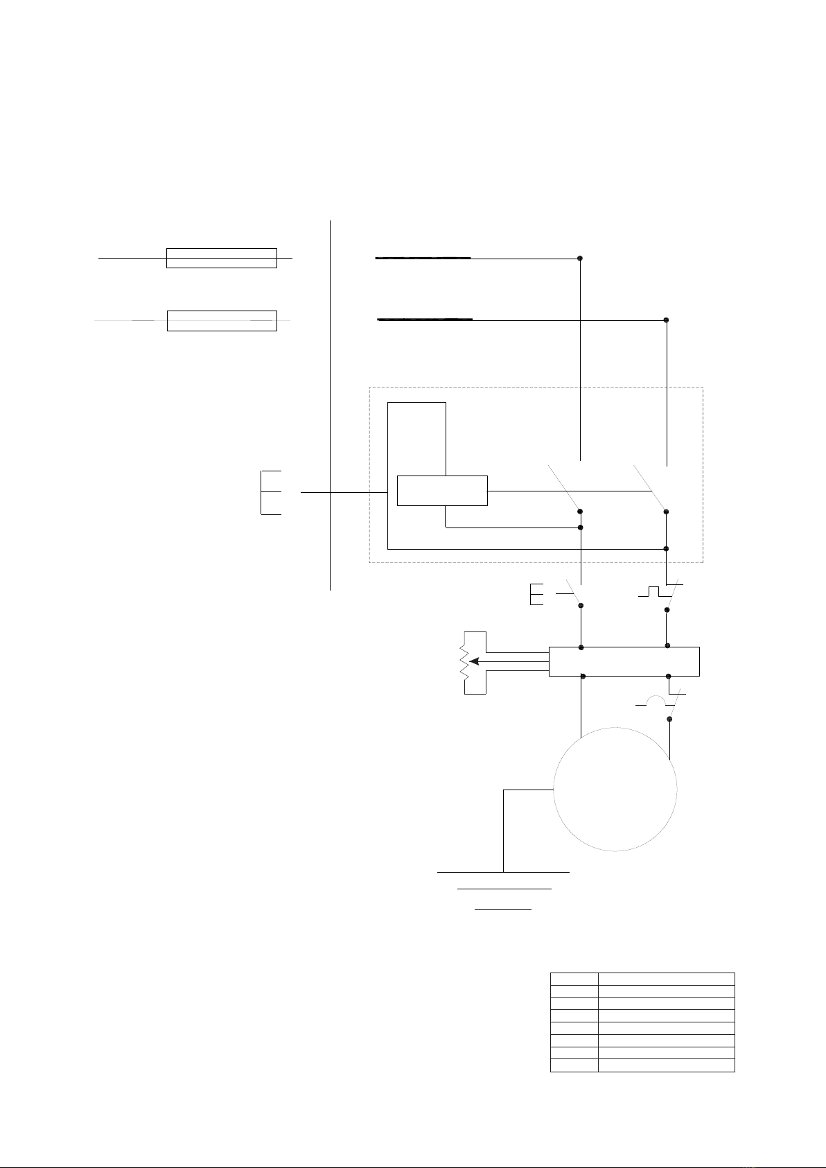
2.5 ELECTRICAL CONNECTION
Check out the plant network on which the machine is connected to
the ground as required by current safety regulations and check out
if the power plug is in good condition.
We reminded to the user that upstream of the network you have to
be protection necessary to safeguard all conductors from short
circuits and overloads.
Rated voltage................................................................. 230 Volt ~
Rated frequency .............................................................. 50/60 Hz
Value max absorption prog .....................................................2.5A
Rated motor speed ......................................... 2000-4200 rev / min
Such protection must be chosen according to the electrical
features of the machine specified below:
Insulation........................................................................... Class B
Nominal power............................................................... 1010 Watt
Intermittent service type ................................................... S4-60%
Power factor............................................................................ 0.96
Sawing machine's motor is also equipped with thermal circuit
breaker protection, which cuts the power supply when the
temperature of the winding becomes too high.
In the case of interruption - because of excess temperature-
waiting for the normal recovery (ca.10 min).
Turn clockwise the knob B to the stop (until the complete packing of
the cup springs) avoiding overtightening.
If it should there be a lack of voltage in the network, wait for it
to re-establish the connection. The electronic regulator and
the main switch include a reset function, which prevents the
automatic restart of the machine. Turn off the main switch
(fig.7D) and reset it, even in case of motor overload.
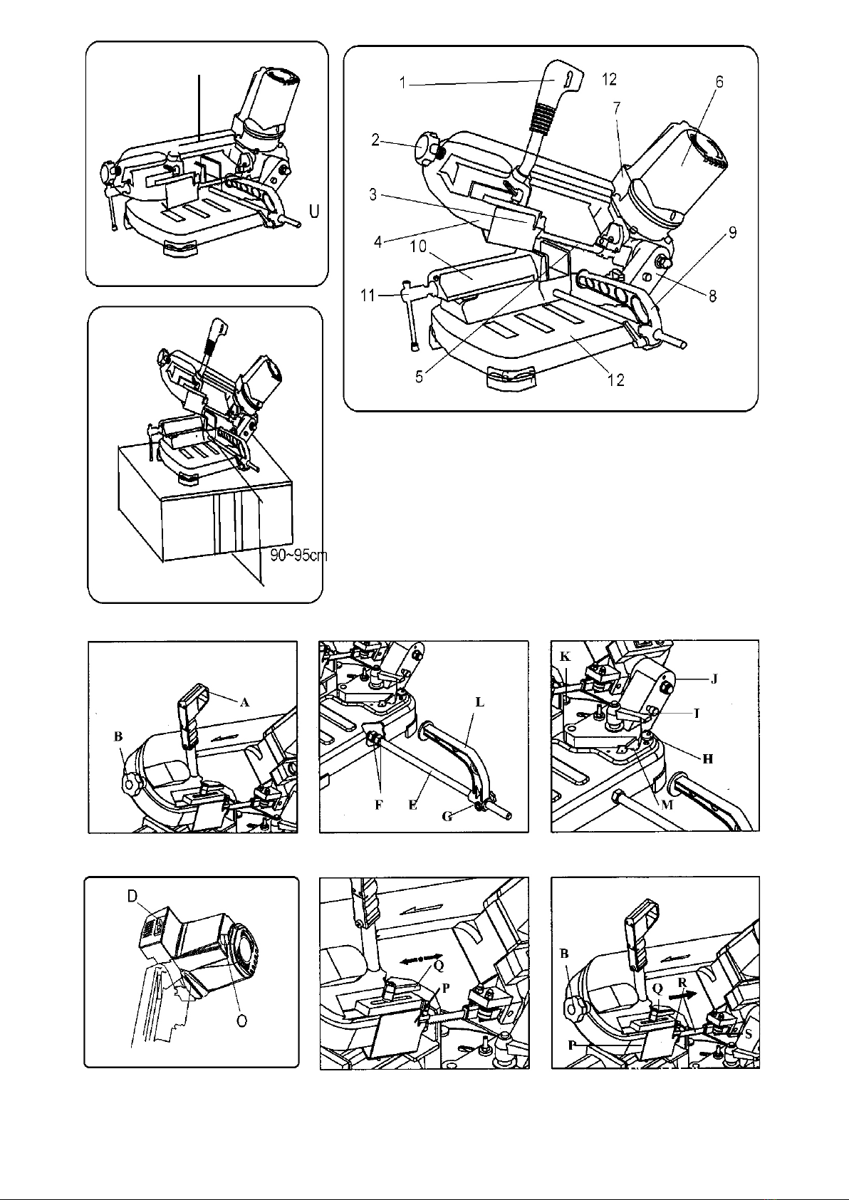
3.0 ADJUSTMENTS (fig.4-5-6-7-8)
3.2 BAR STOP (Fig.5)
If you need to make more cuts pieces of the same length used the
bar stop supplied in order to avoiding repeat all the times the same
measure.
Screw rod E into the hole of the base and lock it with the nut F;
loosen the handwheel G and place the stop L at the required
distance from the blade; locked again the flyer G.
3.3 CUTTING ANGLE (Fig.6)
The sawing machine is enables to make cuts with an angle varying
between 0 ° and 45 ° (0 ° and 60 ° MT-150); simply loosen the knob
I and rotate the turntable to the respective latches.
For all other intermediate angles, rotate the turntable until the
indicator coincides M placed on it with the corresponding position
on the plate.
Then locked again the rotatable support.
3.4 CUTTING SPEED (figure 7)
Your sawing machine is equipped with, an electronic control
system which allows gradual and continuous variation of cutting
speed, adapting it to the type and size of material to be cut (see
CUTTING TABLE).
Then, in order to select the proper speed act on the drive or
increasing it or decreasing it according to your needs.
Example:
Stainless steel: 30 m / min position 1
Steels: 40-60 m / min position 2-3-4
Light alloys: 80 m / min position 6
Tubes and profiles: 70-80 m / min position 5-6
3.5 SLIDING BLADE GUIDE (Figure 8)
The sliding blade guide P with integrated protection that is attached
3.1 BLADE TENSION (figure 4)
If the tighten is too high, the blade tends to come
out from the guides; in this case, slightly loosen
the tension by turning of a turn the handwheel B
anticlockwise.
For best performance, the bi-metal blades that accompany your
sawing machine must undergo to a short break-in procedure.
If after several consecutive cutting machine should suddenly stop,
do not be alarmed: is the thermal protector of the motor, that cuts
the power when the winding temperature reaches the threshold
limit defined the insulation class, avoiding damage to the engine.
4.0 USE
Do not make a proper break-in procedure could
make irreparably compromise the precision
cutting blade.
When all the procedures and operations described so far, you can
start working.
Start now to apply a progressive strain on the piece and finish the
cut.
To make the cut, put yourself in front of the car, and challenged his
right hand grip.
Press with the forefinger of his right hand at the start button (figure
4) and gradually lower the body of the car to get in touch gently the
blade with the workpiece.
Before starting each cutting operation, ensure by
means of a visual check that all guards are intact
and in the proper position.
(see 2.5 )
If during processing were intervene the limiter, lightened slightly
the cutting pressure: this allows among others to safeguard the life
and performance of the blade and to get a cut that is always clean
4.1 RUNNING IN THE BLADE
4.2 OPERATION (figure 7)
The cruise control of your sawing machine is equipped with the
function includes motor protection, obtained by an amperometric
limiter that does not allow him to absorb a higher current than the
set, expressed by the maximum value of absorption programmed
It is therefore necessary to make the first three / four cuts possibly
on a piece full D.40-50mm, exerting pressure on the piece very
slight, increasing it gradually in subsequent cuts.
In this case, release the button and wait for the automatic recovery,
which usually returns after a few minutes.
To realize of what the correct pressure in normal operating
conditions defined by this manual (see CUTTING TABLE),
consider for example that the first cut of steel (es.C40) D.50mm full
must be made in about 4 minutes; after testing, the same
workpiece can be cut easily in about 2 minutes. A running-well
executed, results in a better cut quality, both as a finish that as
precision, and a longer life of the blade.
Switch the main switch D on the position - in this way the machine is
ready to operate.
Between cut and another, during the positioning of the workpiece,
release the button A always, do not try to block it or alter in any way
the functional characteristics.
Keep the left hand still far away from the cutting area and do not
seek in any way to reach during the cutting operations.
to your cutting machine, you can make the cut while maintaining
the guided part of the blade and necessary to fully protect the
unused processing.
Loosen the handle Q and slide the blade guide P so closer or
farther away from the workpiece, as shown in the figure.
To facilitate the replacement of the blade and keep it guided to
better blade guides outside of the sawing machine are eccentric
and adjustable.
3.6 BEARING blade guide (figure 9)
If this is not done, it is uncovered a portion of the
blade not required for processing, which can create a
residual risk of contact with it, as well as affecting the
quality of the cut.
They must always be placed in light contact of the same, but not
completely blocked.
To zoom in or out blade guides you have to simply rotate slightly
with 10mm spanner head screws S.
Pag.5