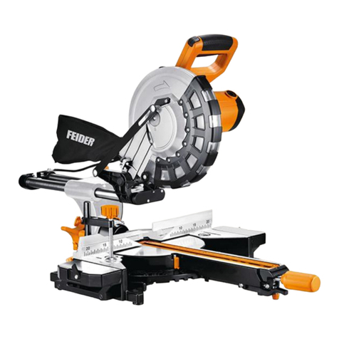
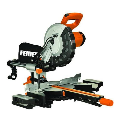
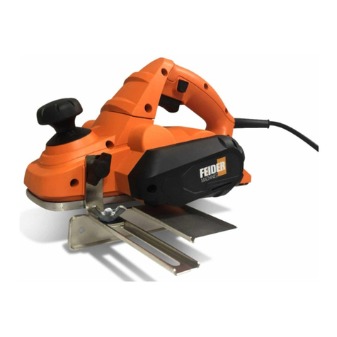
Feider Machines FSOR20V-U User manual

ORIGINAL INSTRUCTIONS
INSTRUCTIONS MANUAL
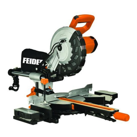
CORDLESS MITRE SAW
FSOR20V-U
WARNING: READ THE FOLLOWING INSTRUCTIONS BEFORE USE THIS MACHINE
BUILDER SAS
32, rue Aristide Bergès - ZI 31270 Cugnaux – France
MADE IN PRC 2020

CONTENTS
• SAFETY INSTRUCTIONS FOR BATTERY CHARGER
• SYMBOLS
• KNOW YOUR PRODUCT
• SPECIFICATIONS
• INTENDED USE
• NOT INTENDED USE
• RESIDUAL RISKS
• GENERAL SAFETY INSTRUCTIONS
• IMPORTANT SAFETY INSTRUCTIONS FOR ALL BATTERY PACKS
• SAFETY RULES FOR LASER LIGHTS
• ADDITIONAL SAFETY RULES FOR MITRE SAWS
• OPERATING INSTRUCTIONS
• MAINTENANCE
• SERVICE
• GUARANTEE

SAFETY INSTRUCTIONS FOR BATTERY
CHARGER
This charger can be used by children
aged from 8 years and above and
persons with reduced physical, sensory
or mental capabilities or lack of
experience and knowledge if they have
been given supervision or instruction
concerning use of the appliance in a safe
way and understand the hazards
involved. Children shall not play with the
appliance. Cleaning and user
maintenance shall not be made by
children without supervision.
If the supply cord is damaged, it must be
replaced by the manufacturer, its service
agent or similarly qualified persons in
order to avoid a hazard.
CAUTION – Do not recharge
non-rechargeable batteries

SYMBOLS
Danger! - Read the operating instructions to reduce the risk of inquiry
Caution! Wear ear-muffs. The impact of noise can cause damage to hearing.
Caution! Wear a breathing mask.
Caution! Wear safety goggles.
Caution! Risk of injury! Do not reach into the running saw blade.
Caution: Laser radiation. Do not look into the beam! Laser
class 2 product!

KNOW YOUR PRODUCT
PARTS LIST
1. Laser light
2. Laser light on/off switch
3. Saw arm
4. Release knob
5. Operating handle
6. Upper fixed blade guard
7. “G” Clamp
8. Rotating blade guard
9. Guard retraction arm
10. Blade bolt cover
11. Dust bag
12. Bevel lock
13. Bevel scale
14. Fence
15. Frame for fixing on workbench
16. Mitre table
17. Mitre scale
18. Table insert
19. Switch trigger
20. Mitre lock knob
21. Mitre latch
22. Spindle lock
23. Slide bars
24. Slide lock
25. Trenching depth adjustment screw
26. Trenching stop
27. Trenching depth lock nut
28. 45°Bevel adjustment screw
29. 0°Bevel adjustment screw
30. Release latch
31. Side support bars (x2)
32. Battery pack
33. Battery lock
34. Switch locker
35. Attach fence

(#) Not all the accessories illustrated or described are
included in standard delivery.
SPECIFICATIONS
• Voltage: 18V (max 20V)
• Battery capacity: 4Ah Li-ion (#)
• No-load speed : 3300/min
• Saw blade: 210mmx30mm
Noise emission
-Sound power level: 98 dB(A) K = 3 dB(A)
-Sound pressure level: 90,4 dB(A) K = 3
dB(A)
The total vibration value does not exceed 2.5 m/s².
Battery:
- Model: FBA20U4
- 20V.d.c, 4Ah, 72 Wh
Charger:
- Model: FFC20U
- Input: 220-240V˜ 50-60Hz 60W
- Output: 20Vd.c. 2,2A
Information:
-The declared vibration total value has been
measured in accordance with a standard test
method and may be used for comparing one tool
with another;
-The declared vibration total value may also be used
in a preliminary assessment of exposure.
Warning:
-The vibration emission during actual use of the
power tool can differ from the declared total value
depending on the ways in which the tool is used;
-need to identify safety measures to protect the
operator that are based on an estimation of
exposure in the actual conditions of use (taking
account of all parts of the operating cycle such as
the times when the tool is switched off and when it is
running idle in addition to the trigger time).
CUTTING CAPACITY
• Mitre table angles: 0° to 45° to the left & right
• Bevel cuts: 0° to 45° to the left
• Straight cut at 0° x 0° : 22 x 7 cm
• Mitre cut at 0° x 45° : 15.5 x 7 cm
• Bevel cut at 45° x 0° : 22x 3.5 cm
• Compound mitre cut at 45° x 45° : 15.5 x 3.5 cm
• Net weight: 9.8 kg
INTENDED USE
This mitre saw is intended for cutting wood and
analogue materials, the saw is not designed for
cutting firewood.
WARNING! When using electric tools basic
safety precautions should always be followed to
reduce the risk of fire, electric shock and personal
injury including the following.
Read all these instructions before attempting to
operate this product and save these instructions.
All persons who use and service the machine have
to be acquainted with this Manual and must be
informed about its potential hazards. Children and
infirm people must not use this tool. Children should
be supervised at all times if they are in the area in
which the tool is being used. It is also imperative that
you observe the accident prevention regulations in
force in your area. The same applies for general
rules of occupational health and safety
Even when the tool is used as prescribed it is not
possible to eliminate all residual risk factors. The
following hazards may arise in connection with the
tool’s construction and design:
·Contact with the blade.
· Kickback of workpiece
· Blade fracture.
·Catapulting of blade pieces.
· Damage to hearing if effective earmuffs are not
worn.
·Harmful emissions of sawdust when the machine is
used in closed rooms. Always use supplementary
dust extraction where possible.
· Do not use blades that are deformed or cracked.
·Always remove the plug from the mains socket
before making any adjustments or maintenance,
including changing the blade. To ensure safe
operation of the mitre saw you must follow these
guidelines:
· Select the correct blade for the material to be cut.
·Do not use the saw to cut materials other than those
recommended by the manufacturer.
The mitre saw can be safely carried by the main
handle but only once it has been removed from
the mains power and secured in the locked down
position.

· Do not use the saw without the guards in position,
in good working order and properly maintained.
· Ensure that the arm is properly secure when
beveling.
· Keep the floor area around the machine level, well
maintained and free of loose materials.
· Provide adequate lighting.
· Ensure that you are trained in the use, adjustment
and operation of the machine.
· Use correctly sharpened blades and observe the
maximum speed marked on the blade.
· Do not remove any cut-offs from the cutting area
until the guard is fully locked in place and the
blade has come to rest.
· Ensure that the mitre saw is fixed to a work bench
wherever possible.
· When cutting long pieces which extend well over
the table width ensure that the ends are
adequately supported at the same height as the
saw table top. Supports should be positioned in
such a way to ensure that the workpiece does not
fall to the ground. once the cut has been made. A
number of supports at regular intervals may be
required if the workpiece is extremely long.
NOT INTENDED USE
If not intended use, there are risk of fire, electric
shock and personal injury. The provisions contained
in this guarantee are not intended to limit, modify,
take away from, disclaim or exclude any statutory
guarantee set forth in any applicable provincial or
federal legislation.
RESIDUAL RISKS
Even if you use this electric power tool in
accordance with instructions, certain residual
risks cannot be rules out. The following hazards
may arise in connection with the equipment’s
construction and layout:
1. Lung damage if no suitable protective dust mask is
used.
2. Damage to hearing if no suitable ear protection is
used.
3. Health damage caused by hand-arm vibrations if
the equipment is used over a prolonged period or is
not properly guided and maintained.
General power tool safety warnings
WARNING Read all safety warnings, instructions,
illustrations and specifications provided with this
power tool. Failure to follow all instructions listed
below may result in electric shock, fire and/or serious
injury.
Save all warnings and instructions for future
reference.
The term "power tool" in the warnings refers to your
mains-operated (corded) power tool or
battery-operated (cordless) power tool.
1) Work area safety
a) Keep work area clean and well lit.Cluttered or
dark areas invite accidents.
b) Do not operate power tools in explosive
atmospheres, such as in the presence of
flammable liquids, gases or dust. Power tools
create sparks which may ignite the dust or fumes.
c) Keep children and bystanders away while
operating a power tool. Distractions can cause you
to lose control.
2) Electrical safety
a) Power tool plugs must match the outlet. Never
modify the plug in any way. Do not use any
adapter plugs with earthed (grounded) power
tools. Unmodified plugs and matching outlets will
reduce risk of electric shock.
b) Avoid body contact with earthed or grounded
surfaces, such as pipes, radiators, ranges and
refrigerators. There is an increased risk of electric
shock if your body is earthed or grounded.
c) Do not expose power tools to rain or wet
conditions. Water entering a power tool will
increase the risk of electric shock.
d) Do not abuse the cord. Never use the cord for
carrying, pulling or unplugging the power tool.
Keep cord away from heat, oil, sharp edges or
moving parts. Damaged or entangled cords
increase the risk of electric shock.
e) When operating a power tool outdoors, use an
extension cord suitable for outdoor use. Use of a
cord suitable for outdoor use reduces the risk of
electric shock.
f) If operating a power tool in a damp location is
unavoidable, use a residual current device (RCD)
protected supply. Use of an RCD reduces the risk
of electric shock.
3) Personal safety
a) Stay alert, watch what you are doing and use
common sense when operating a power tool. Do
not use a power tool while you are tired or under
the influence of drugs, alcohol or medication. A
moment of inattention while operating power tools
may result in serious personal injury.
b) Use personal protective equipment. Always
wear eye protection. Protective equipment such as
a dust mask, non-skid safety shoes, hard hat or
hearing protection used for appropriate conditions
will reduce personal injuries.
c) Prevent unintentional starting. Ensure the
switch is in the off-position before connecting to
power source and/or battery pack, picking up or
carrying the tool. Carrying power tools with your
finger on the switch or energising power tools that
have the switch on invites accidents.

d) Remove any adjusting key or wrench before
turning the power tool on. A wrench or a key left
attached to a rotating part of the power tool may
result in personal injury.
e) Do not overreach. Keep proper footing and
balance at all times. This enables better control of
the power tool in unexpected situations.
f) Dress properly. Do not wear loose clothing or
jewellery. Keep your hair and clothing away from
moving parts. Loose clothes, jewellery or long hair
can be caught in moving parts.
g) If devices are provided for the connection of
dust extraction and collection facilities, ensure
these are connected and properly used. Use of
dust collection can reduce dust-related hazards.
h) Do not let familiarity gained from frequent use
of tools allow you to become complacent and
ignore tool safety principles. A careless action can
cause severe injury within a fraction of a second.
4) Power tool use and care
a) Do not force the power tool. Use the correct
power tool for your application. The correct power
tool will do the job better and safer at the rate for
which it was designed.
b) Do not use the power tool if the switch does
not turn it on and off. Any power tool that cannot be
controlled with the switch is dangerous and must be
repaired.
c) Disconnect the plug from the power source
and/or remove the battery pack, if detachable,
from the power tool before making any
adjustments, changing accessories, or storing
power tools. Such preventive safety measures
reduce the risk of starting the power tool accidentally.
d) Store idle power tools out of the reach of
children and do not allow persons unfamiliar with
the power tool or these instructions to operate
the power tool.
Power tools are dangerous in the hands of untrained
users.
e) Maintain power tools and accessories. Check
for misalignment or binding of moving parts,
breakage of parts and any other condition that
may affect the power tool’s operation. If damaged,
have the power tool repaired before use. Many
accidents are caused by poorly maintained power
tools.
f) Keep cutting tools sharp and clean. Properly
maintained cutting tools with sharp cutting edges are
less likely to bind and are easier to control.
g) Use the power tool, accessories and tool bits
etc. in accordance with these instructions, taking
into account the working conditions and the
work to be performed. Use of the power tool for
operations different from those intended could result
in a hazardous situation.
h) Keep handles and grasping surfaces dry,
clean and free from oil and grease. Slippery
handles and grasping surfaces do not allow for safe
handling and control of the tool in unexpected
situations.
5) Battery tool use and care
a) Recharge only with the charger specified by
the manufacturer.A charger that is suitable for one
type of battery pack may create a risk of fire when
used with another battery pack.
b) Use power tools only with specifically
designated battery packs. Use of any other battery
packs may create a risk of injury and fire.
c) When battery pack is not in use, keep it away
from other metal objects, like paper clips, coins,
keys, nails, screws or other small metal objects,
that can make a connection from one terminal to
another.Shorting the battery terminals together may
cause burns or a fire.
d) Under abusive conditions, liquid may be
ejected from the battery; avoid contact. If contact
accidentally occurs, flush with water. If liquid
contacts eyes, additionally seek medical help.
Liquid ejected from the battery may cause irritation
or burns.
e) Do not use a battery pack or tool that is
damaged or modified.Damaged or modified
batteries may exhibit unpredictable behaviour
resulting in fire, explosion or risk of injury.
f) Do not expose a battery pack or tool to fire or
excessive temperature.Exposure to fire or
temperature above 130 °C may cause explosion.
NOTE The temperature „130 °C“ can be replaced by
the temperature „265 °F“.
g) Follow all charging instructions and do not
charge the battery pack or tool outside the
temperature range specified in the instructions.
Charging improperly or at temperatures outside the
specified range may damage the battery and
increase the risk of fire.
6) Service
a) Have your power tool serviced by a qualified
repair person using only identical replacement
parts. This will ensure that the safety of the power
tool is maintained.
b) Never service damaged battery packs. Service
of battery packs should only be performed by the
manufacturer or authorized service providers.
Safety instructions for mitre saws
a) Mitre saws are intended to cut wood or
wood-like products, they cannot be used with
abrasive cut-off wheels for cutting ferrous
material such as bars, rods, studs, etc. Abrasive
dust causes moving parts such as the lower guard to

jam. Sparks from abrasive cutting will burn the lower
guard, the kerf insert and other plastic parts.
b) Use clamps to support the workpiece
whenever possible. If supporting the workpiece
by hand, you must always keep your hand at
least 100 mm from either side of the saw blade.
Do not use this saw to cut pieces that are too
small to be securely clamped or held by hand. If
your hand is placed too close to the saw blade, there
is an increased risk of injury from blade contact.
c) The workpiece must be stationary and
clamped or held against both the fence and the
table. Do not feed the workpiece into the blade or
cut “freehand” in any way. Unrestrained or moving
workpieces could be thrown at high speeds, causing
injury.
d) Push the saw through the workpiece. Do not
pull the saw through the workpiece. To make a
cut, raise the saw head and pull it out over the
workpiece without cutting, start the motor, press
the saw head down and push the saw through
the workpiece. Cutting on the pull stroke is likely to
cause the saw blade to climb on top of the workpiece
and violently throw the blade assembly towards the
operator.
e) Never cross your hand over the intended line
of cutting either in front or behind the saw blade.
Supporting the workpiece “cross handed” i.e. holding
the workpiece to the right of the saw blade with your
left hand or vice versa is very dangerous.
f) Do not reach behind the fence with either hand
closer than 100 mm from either side of the saw
blade, to remove wood scraps, or for any other
reason while the blade is spinning. The proximity
of the spinning saw blade to your hand may not be
obvious and you may be seriously injured.
g) Inspect your workpiece before cutting. If the
workpiece is bowed or warped, clamp it with the
outside bowed face toward the fence. Always
make certain that there is no gap between the
workpiece, fence and table along the line of the
cut. Bent or warped workpieces can twist or shift and
may cause binding on the spinning saw blade while
cutting. There should be no nails or foreign objects in
the workpiece.
h) Do not use the saw until the table is clear of all
tools, wood scraps, etc., except for the
workpiece. Small debris or loose pieces of wood or
other objects that contact the revolving blade can be
thrown with high speed.
i) Cut only one workpiece at a time. Stacked
multiple workpieces cannot be adequately clamped
or braced and may bind on the blade or shift during
cutting.
j) Ensure the mitre saw is mounted or placed on a
level, firm work surface before use. A level and
firm work surface reduces the risk of the mitre saw
becoming unstable.
k) Plan your work. Every time you change the
bevel or mitre angle setting, make sure the
adjustable fence is set correctly to support the
workpiece and will not interfere workpiece on the
table, move the saw blade through a complete
simulated cut to assure there will be no interference
or danger of cutting the fence.
l) Provide adequate support such as table
extensions, saw horses, etc. for a workpiece that
is wider or longer than the table top.Workpieces
longer or wider than the mitre saw table can tip if not
securely supported. If the cut-off piece or workpiece
tips, it can lift the lower guard or be thrown by the
spinning blade.
m) Do not use another person as a substitute for
a table extension or as additional support.
Unstable support for the workpiece can cause the
blade to bind or the workpiece to shift during the
cutting operation pulling you and the helper into the
spinning blade.
n) The cut-off piece must not be jammed or
pressed by any means against the spinning saw
blade. If confined, i.e. using length stops, the cut-off
piece could get wedged against the blade and
thrown violently.
o) Always use a clamp or a fixture designed to
properly support round material such as rods or
tubing. Rods have a tendency to roll while being cut,
causing the blade to “bite” and pull the work with
your hand into the blade.
p) Let the blade reach full speed before
contacting the workpiece. This will reduce the risk
of the workpiece being thrown.
q) If the workpiece or blade becomes jammed,
turn the mitre saw off. Wait for all moving parts
to stop and disconnect the plug from the power
source and/or remove the battery pack. Then
work to free the jammed material. Continued
sawing with a jammed workpiece could cause loss of
control or damage to the mitre saw.
r) After finishing the cut, release the switch, hold
the saw head down and wait for the blade to stop
before removing the cut-off piece. Reaching with
your hand near the coasting blade is dangerous.
s) Hold the handle firmly when making an
incomplete cut or when releasing the switch
before the saw head is completely in the down
position. The braking action of the saw may cause
the saw head to be suddenly pulled downward,
causing a risk of injury.
Use only a saw blade diameter in accordance with
the markings on the saw and information about the
bore diameter and the maximum kerf of the saw
blade.

Use only saw blades that are marked with a speed
equal or higher than the speed marked on the tool.
Adjust the saw for proper cutting capacity, if
applicable.
If adjustable and/or removable workpiece support
extensions are provided always fix and use these
extensions during operation.
Avoid overheating the saw blade tips.
Use only saw blades recommended by the
manufacturer, which conform to EN 847-1.
Always check if the saw blade guard is working
properly. It shall be well assembled, and it shall be
easily moving with hand and that it can be locked
when operating the tool (see in instructions for use).
IMPORTANT SAFETY INSTRUCTIONS FOR ALL
BATTERY PACKS
When ordering replacement battery packs, be sure to
include the catalog number and voltage. Consult the
technical specifications for compatibility of chargers
and battery packs. The battery pack is not fully
charged out of the carton. Before using the battery
pack and charger, read the safety instructions below
and then follow charging procedures outlined.
• Do not charge or use the battery pack in
explosive atmospheres, such as in the
presence of flammable liquids, gases or dust.
Inserting or removing the battery pack from the
charger may ignite the dust or fumes.
• NEVER force the battery pack into the charger.
DO NOT modify the battery pack in any way to fit
into a non-compatible charger as battery pack
may rupture causing serious personal injury.
• Charge the battery packs only in designated
chargers.
• DO NOT splash or immerse in water or other
liquids.
• Do not store or use the tool and battery pack in
locations where the temperature may reach or
exceed 104 °F (40 °C) (such as outside sheds
or metal buildings in summer). For best life store
battery packs in a cool, dry location.
NOTE: Do not store the battery packs installed
in the tool.
The battery should be charged and used at ambient
temperatures between 10 and 40°C (ideally around
20°C).
Store the battery in a safe place, out of reach of
children, in an ambient temperature between 10
and 40°C.
WARNING: Fire hazard. Never attempt to
open the battery pack for any reason. If the battery
pack case is cracked or damaged, do not insert
into the charger. Do not crush, drop or damage the
battery pack. Do not use a battery pack or charger
that has received a sharp blow, been dropped, run
over or damaged in any way (e.g., pierced with a
nail, hit with a hammer, stepped on). Damaged
battery packs should be returned to the service
center for recycling.
SPECIFIC SAFETY INSTRUCTIONS FOR LITHIUM
ION (Li-Ion)
• Do not incinerate the battery pack even if it is
severely damaged or is completely worn out.
The battery pack can explode in a fire. Toxic
fumes and materials are created when lithium ion
battery packs are burned.
• If battery contents come into contact with the
skin, immediately wash area with mild soap
and water. If battery liquid gets into the eye, rinse
water over the open eye for 15 minutes or until
irritation ceases. Consult a doctor.
• Contents of opened battery cells may cause
respiratory irritation. Provide fresh air. If
symptoms persist, seek medical attention.
WARNING: Burn hazard. Battery liquid may
be flammable if exposed to spark or flame.
SAFETY RULES FOR LASER LIGHTS
WARNING Before connecting a tool to a
power source (mains switch power point receptacle,
outlet, etc.) be sure that the voltage supply is the
same as that specified on the nameplate of the tool.
A power source with a voltage greater than that
specified for the tool can result in serious injury to
the user, as well as damage to the tool. If in doubt,
do not plug in the tool. Using a power source with a
voltage less than the nameplate rating is harmful to
the motor. Your tool is double insulated for additional
protection against a possible electrical insulation
failure within the tool.
OPERATING INSTRUCTIONS

ACCESSORIES
The Compound Mitre Saw is supplied with the following
accessories as standard:
• Saw blade (fitted)
• 6mm hex key
• Dust bag
• Instruction manual
• Battery capacity: 4Ah Li-ion (#)
• Charger (#)
(#) Not all the accessories illustrated or described are
included in standard delivery.
TRANSPORTATION
Lift the mitre saw only when the saw arm is locked in the
down position, the saw is switched off and the battery is
removed from the power tool.
Only lift the saw by the operating handle (5) or outer
castings. Do not lift the saw using the guards.
BENCH MOUNTING
The saw base has holes in each corner to facilitate bench
mounting.
1. Place the saw on a level, horizontal bench or work
table using bolts (not supplied) and fix the saw to the
bench using 4 bolts.
2. If desired, you can mount the saw to a piece of 1/2” (13
mm) or thicker plywood which can then be clamped to
your work support or moved to other job sites and
re-clamped.
CAUTION. Make sure that the mounting surface is not
warped as an uneven surface can cause binding and
inaccurate sawing.
RELEASE KNOB
The release knob (4) is provided for holding the cutting
head down while transporting or storing the mitre saw.
The saw must never be used with the release knob
locking the head down.
MITRE TABLE LOCKS
The mitre table locks (20) are used to lock the table at the
desired mitre angle.
The mitre saw cuts from 0° to 45° both left and right. To
adjust the mitre angle loosen the mitre table locks(20)(21)
and rotate the mitre table to the desired position.
The mitre table features positive click stops at 0°, 15°,
22.5°, 30° and 45° for quick setting of common mitre
angles.
BEVEL LOCK
The bevel lock (12) is used to set the blade at the desired
bevel angle. The mitre saw bevel cuts from 0° to 45° to
the left. To adjust the bevel angle loosen the bevel lock
and adjust the saw arm to the desired bevel angle.
SPINDLE LOCK BUTTON
The spindle lock button (22) prevents the blade in the
saw from rotating. Depress and hold the spindle lock
button while installing, changing, or removing the blade.
ROTATING LOWER BLADE GUARD
The rotating lower blade guard (8) provides protection from
both sides of the blade. It retracts over the upper blade
guard (6) as the saw is lowered into the workpiece.
TURNING ON AND OFF
1. To turn the saw on press switch lock (34) to left and
depress and hold the on/off trigger switch (19)
2. To turn the saw off release the switch lock (34) and
on/off trigger switch (19).
DUST EXTRACTION
1. Fit the dust bag (11) to the dust extraction port.
2. A vacuum dust extraction device can be connected to
the dust extraction port. Use a suitable vacuum adapt or if
necessary. The dust extraction port has an internal
diameter of 40 mm.
SETTING THE TABLE SQUARE WITH THE BLADE
1. Make sure that the battery is removed from the power
point.
2. Push the saw arm (3) down to its lowest position and
engage the release knob (4) to hold the saw arm in the
transport position.
3. Loosen the mitre locks (20) and lifting up the mitre
latch(21) .
4. Rotate the table (16) until the pointer is positioned at 0°.
5. Release mitre latch(21) and tighten the mitre locks (20).
6. Loosen the bevel lock (12) and set the saw arm (3) at
0°bevel (the blade at 90°to the mitre table). Tighten the
bevel lock (12).
7. Place a set square against the table (16) and the flat part
of the blade.
8. Rotate the blade by hand and check the blade-to-table
alignment at several points.
9. The edge of the set square and the saw blade should be
parallel.
10. If the saw blade angles away from the set square,
adjust as follows.
11. Use an 10 mm wrench or adjustable wrench to loosen
the lock nut securing the 0° bevel adjustment screw (29).
Also, loosen the bevel lock (12).
12. Adjust the 0° bevel adjustment screw (29) using a 4
mm hex key to bring the saw blade into alignment with the
square.
13. Loosen the Phillips head screw holding the pointer of
the bevel scale (13) and adjust the position of the pointer
so that it accurately indicates zero on the scale. Retighten
the screw.
14. Retighten the bevel lock (12) and the lock nut securing
the 0° bevel adjustment screw (29).
SETTING THE FENCE SQUARE WITH THE TABLE
1. Make sure that the battery is removed from the power
point.
2. Push the saw arm (3) down to its lowest position and
engage the release knob (4) to hold the saw arm in the
transport position.
3. Loosen the mitre locks (20) and lifting up the mitre latch
(21).
4. Rotate the table (16) until the pointer is positioned at 0°.
5. Release mitre latch (21) and tighten the mitre locks (20).

6. Using a 5 mm hex key, loosen the two screws securing
the fence (14) to the base.
7. Place a square against the fence (14) and alongside
the blade.

8. Adjust the fence (14) until it is square with the blade.
9. Tighten the screws securing the fence (14).
10. Loosen the Phillips head screw holding the pointer of
the mitre scale (17) and adjust it so that it accurately
indicates the zero position on the mitre scale.
11. Retighten the screw securing the mitre scale pointer.
CHANGING A BLADE
1. Make sure that the battery is removed from the power
point.
2. Push down on the operating handle (5) and pull the
release knob (4) to disengage the saw arm (3).
3. Raise the saw arm (3) to its highest position.
4. Loosen the cover plate screw about 2 turns with a
Phillips screwdriver. Do not remove this screw from the
tool.
5. Pull the rotating blade guard (8) down. When the
rotating blade guard (8) is positioned over the upper fixed
blade guard (6) it is possible to access the blade bolt.
6. Lift and hold up the lower blade guard (8) to expose
the threaded blade bolt.
7. Hold the rotating guard (8) up and press the spindle
lock button (22). Rotate the blade until the spindle locks.
8. Use the 6 mm hex key provided to loosen and remove
the blade bolt. (Loosen in a clockwise direction as the
blade screw has a left hand thread).
9. Remove the flat washer, outer blade washer and the
blade.
10. Wipe a drop of oil onto the inner blade washer and
the outer blade washer where they contact the blade.
11. Fit the new blade onto the spindle taking care that the
inner blade washer sits behind the blade.
12. Replace the outer blade washer.
13. Depress the spindle lock button (22) and replace the
flat washer and blade bolt.
14. Use the 6 mm hex key to tighten the blade bolt
securely (tighten in an anti-clockwise direction).
15. Lower the blade guard, hold the rotating lower blade
guard (8) and blade bolt cover (10) in position and tighten
the fixing screw to secure the blade bolt cover in position.
16. Check that the blade guard operates correctly and
covers the blade as the saw arm is lowered.
17. Connect the saw to the power supply and run the
blade to make certain that it is operating correctly.
CROSS CUT
If possible, always use a clamping device such as a ‘G"
clamp to secure your workpiece.
When cutting your workpiece, keep your hands well away
from the blade area.
Do not remove a cut-off piece on the right-hand side of
the blade using your left hand.
A crosscut is made by cutting across the grain of the
workpiece. A 90°crosscut is made with the mitre table set
at 0°. Mitre crosscuts are made with the table set at some
angle other than zero.
1. Pull on the release knob (4) and lift the saw arm (3) to its
full height.
2. Loosen the mitre locks (20) and lifting up the mitre
latch(21) .
3. Rotate the mitre table (16) until the pointer aligns with
the desired angle.
4. Release mitre latch(21) and retighten the mitre locks
(20).
5. Place the workpiece flat on the table with one edge
securely against the fence (14). If the board is warped,
place the convex side against the fence (14). If the concave
side is placed against the fence, the board could break and
jam the blade.
6. When cutting long pieces of timber, support the opposite
end of the timber with side support bars, a roller stand or a
work surface that is level with the saw table.
7. Before turning on the saw, perform a dry run of the
cutting operation to check that there are no problems such
as a clamp interfering with the cutting action.
8. Hold the operating handle (5) firmly and squeeze the
release latch (30). Allow the blade to reach maximum
speed and slowly lower the blade into and through the
workpiece.
9. Release the switch trigger (19) and allow the saw blade
to stop rotating before raising the blade out of the
workpiece. Wait until the blade stops before removing the
workpiece.
BEVEL CUT
If possible, always use a clamping device such as a ‘G"
clamp to secure your workpiece.
When cutting your workpiece, keep your hands well away
from the blade area.
Do not remove a cut-off piece on the right-hand side of the
blade using your left hand.
A bevel cut is made by cutting across the grain of the
workpiece with the blade angled to the fence and mitre
table. The mitre table is set at the zero degree position and
the blade set at an angle between 0°and 45°.
1. Pull on the release knob (4) and lift the saw arm to its full
height.
2. Loosen the mitre locks (20) and lifting up the mitre latch
(21).
3. Rotate the mitre table (16) until the pointer aligns with
zero on the mitre scale (17).
4. Release mitre latch (21) and retighten the mitre locks
(20).
5. Loosen the bevel lock (12) and move the saw arm (3) to
the left to the desired bevel angle (between 0°and 45°).
Tighten the bevel lock (12).
6. Place the workpiece flat on the table with one edge
securely against the fence (14). If the board is warped,
place the convex side against the fence. If the concave
side is placed against the fence, the board could break and
jam the blade.
7. When cutting long pieces of timber, support the opposite
end of the timber with side support bars, a roller stand or a

work surface that is level with the saw table.
8. Before turning on the saw, perform a dry run of the
cutting operation to check that there are no problems
such as a clamp interfering with the cutting action.
9. Hold the operating handle (5) firmly and squeeze the
release latch (30). Allow the blade to reach maximum
speed and slowly lower the blade into and through the
workpiece.
10. Release the switch trigger (19) and allow the saw
blade to stop rotating before raising the blade out of the
workpiece. Wait until the blade stops before removing the
workpiece.
ATTACH FENCE
1. For cutting safety always use two attach fence.
2. If use bevel cut , drag out the attach fence. The attach
fence distance moving parts about 3-8mm at any times.
COMPOUND MITRE CUT
If possible, always use a clamping device such as a ‘G"
clamp to secure your workpiece.
When cutting your workpiece, keep your hands well away
from the blade area.
Do not remove a cut-off piece on the right-hand side of
the blade using your left hand.
A compound mitre cut involves using a mitre angle and a
bevel angle at the same time. It is used in making picture
frames, to cut mouldings, making boxes with sloping
sides and for roof framing. Always make a test cut on a
piece of scrap wood before cutting into the good material.
1. Pull on the release knob (4) and lift the saw arm to its
full height.
2. Loosen the mitre locks (20) and lifting up the mitre
latch (21) ..
3. Rotate the mitre table (16) until the pointer aligns with
the desired angle on the mitre scale (17).
4. Release mitre latch (21) and retighten the mitre locks
(20).
5. Loosen the bevel lock (12) and move the saw arm (3)
to the left to the desired bevel angle (between 0°and 45°).
Tighten the bevel lock (12).
6. Place the workpiece flat on the table with one edge
securely against the fence (14). If the board is warped,
place the convex side against the fence. If the concave
side is placed against the fence, the board could break
and jam the blade.
7. When cutting long pieces of timber, support the
opposite end of the timber with the side support bars, a
roller stand or a work surface that is level with the saw
table.
8. Before turning on the saw, perform a dry run of the
cutting operation to check that there are no problems
such as a clamp interfering with the cutting action.
9. Hold the operating handle (5) and firmly and squeeze
the release latch (30). Allow the blade to reach maximum
speed and slowly lower the blade into and through the
workpiece.
10. Release the switch trigger (19) and allow the saw
blade to stop rotating before raising the blade out of the
workpiece. Wait until the blade stops before removing the
workpiece.
To Slide Cut Wide Boards
To slide cut wide boards, Unlock the slide lock knob (24)
and allow the cutting head assembly to move freely.
SETTING CUTTING DEPTH
The depth of cut can be preset for even and repetitive
shallow cuts.
1. Slide the stop plate (24) towards the front position.
2. Loosen the lock nut (25) to free the lock knob (23), turn
the stop knob until the cutting head down until the teeth of
the blade are at the desired depth.
3. While holding the upper arm in that position, tighten the
lock nut to secured the stop knob.
4. Recheck the blade depth by moving the cutting head
front to back through the full motion of typical cut along the
control arm.
TO REMOVE OR INSTAL BATTERY PACK
WARNING: Never remove the battery pack while the
tool is working.
Depress the battery pack lock button to release and slide
the battery pack out from your tool. After recharge, slide it
back into your tool. A simple push and slight pressure will
be sufficient.
CHARGING THE BATTERY PACK
1. The battery charge supplied (according the model) is
matched to the battery installed in the machine. Do not use
another battery charger.
2. The battery pack is protected against deep discharging.
When the battery pack is empty, the machine is switched
off by means of a protective circuit.
3. Connect the charger to the power supply. The charger
lights up (green light indicator). Insert the battery into the
charger, the indicator light turns red. The battery is
charging. When the charge is finished, the indicator light
changes color. You can remove the battery from the
charger.
MAINTENANCE
1. Store the tool, instruction manual and accessories in a
secure place. In this way you will always have all the
information and parts on hand.
2. Keep the tool’s air vents unclogged and clean at all
times.
3. Remove dust and dirt regularly. Cleaning is best done
with compressed air or a rag.
4. Never use caustic agents to clean plastic parts.
GENERAL INSPECTION
1. Regularly check that all the fixing screws are tight.
They may vibrate loose over time.
SERVICE
• Tool service must be performed only by qualified repair
personnel. Service or maintenance performed by

unqualified personnel could result in a risk of injury.
• When servicing a tool, use only identical replacement
parts. Follow instructions in the Maintenance section of
this manual. Use of unauthorized parts or failure to follow
Maintenance Instructions may create a risk of electric
shock or injury.
GUARANTEE
We guarantee this product for 2 full years.
The warranty period for this item starts on the day of
purchase. You can prove the date of purchase by
sending us the original receipt.
We insure over the entire warranty period:
• Free repair of possible malfunctions.
• Free replacement of damaged parts.
• Including the free service of our specialized
personnel (i.e. free assembly by our technicians)
Provided that the damage is not due to improper use of
the device.
To help you with your product, we invite you to use this
link or call us on +33 (0)9 70 75 30 30:
https://services.swap-europe.com/contact
You must create a "ticket" via their platform:
• Register or create your account
• Indicate the reference of the tool
• Choose the subject of your request
• Explain your problem
• Attach these files: Invoice or receipt, identification
plate photo (serial number), photo of the part you need
(eg broken transformer plug pins)
DECLARATION OF CONFORMITY
EC Declaration of conformity
BUILDER SAS
32, rue Aristide Bergès - ZI 31270 Cugnaux – France
Declares that the machine
Designation: CORDLESS MITRE SAW
FSOR20V-U
Serial number: 20200322292-20200323343
Is in conformity with the European Directives:
Machine Directive 2006/42/EC
EMC Directive 2014/30/EU
RoHS Directive 2011/65/EU+(EU) 2015/863
Noise directive 2000/14/EC +Annex VI & 2005/88/EC
This product is also in conformity with the following
standards:
EN 62841-1:2015
EN 62841-3-9:2014
EN55014-1:2017
EN55014-2:2015
Responsible of the technical file: Mr Olivier Patriarca
Cugnaux, 31/12/2019
Philippe MARIE / PDG
Table of contents
Other Feider Machines Saw manuals

Feider Machines
Feider Machines FSSAB20V-B User manual

Feider Machines
Feider Machines FRX600 User manual

Feider Machines
Feider Machines FDL125 User manual

Feider Machines
Feider Machines FSC20235 User manual

Feider Machines
Feider Machines FSC1485 User manual

Feider Machines
Feider Machines FSO20254 User manual

Feider Machines
Feider Machines FSOR254S2L User manual

Feider Machines
Feider Machines FSOR17210 User manual

Feider Machines
Feider Machines FRB900 User manual

Feider Machines
Feider Machines F405SC3F User manual