Montageanleitung ID RW02.ABCD-A / -B / -AL / -BL
FEIG ELECTRONIC GmbH Seite 9 von 22
D E U T S C H
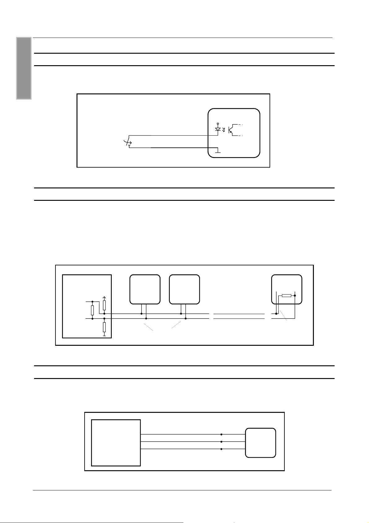
5. Montage:
Bei der Montage ist darauf zu achten, daß der Leser nicht direkt auf leitende Materialien wie
Metallflächen, Metallgitter (Armierung) oder metallisierte Oberflächen montiert wird. Diese Oberflä-
chen bewirken eine Bedämpfung des Magnetfeldes und damit verbunden eine Reduzierung der
Lesereichweite. Ist eine Montage dennoch auf Metall notwendig, so ist der Leser mit einem Ab-
stand von min. 3 cm zu diesen Oberfläschen zu montieren.
Der räumliche Abstand zu benachbarten Lesern gleicher Bauart sollte 30 cm nicht unterschrei-
ten.
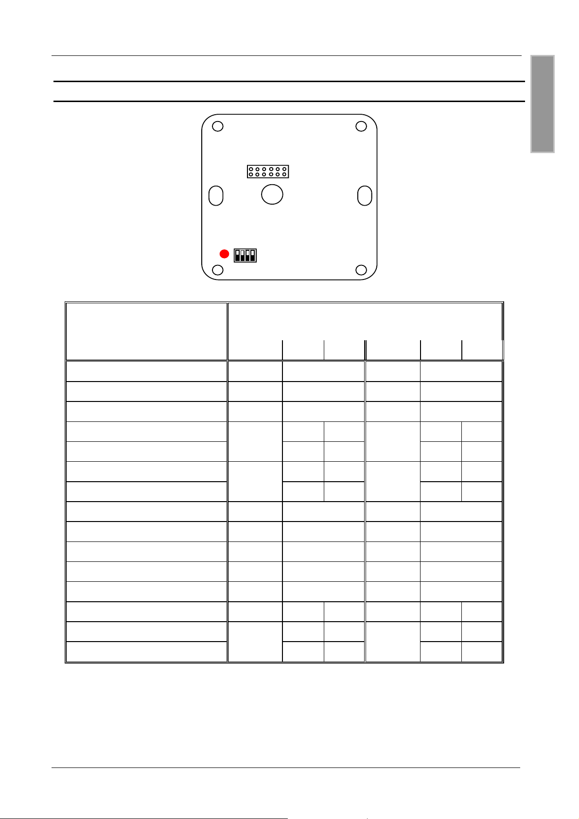
5.1 ID RW02.ABCD-A/ -B:
Der Leser ist für die Montage auf handelsüblichen Schalterdosen konzipiert und kann mit den bei-
liegenden Schrauben direkt auf eine solche Schalterdose geschraubt werden.
Ist eine Montage auf einer Metalloberfläche notwendig, kann zur Einhaltung des Mindesabstandes
der Gehäuserahmen ID APG-A von FEIG ELECTRONIC bezogen werden.
Hinweis;
Nach Abschluß der Klemm- und Montagearbeiten und noch vor der Befestigung des Auf-
klebers sollte die Funktion getestet werden!
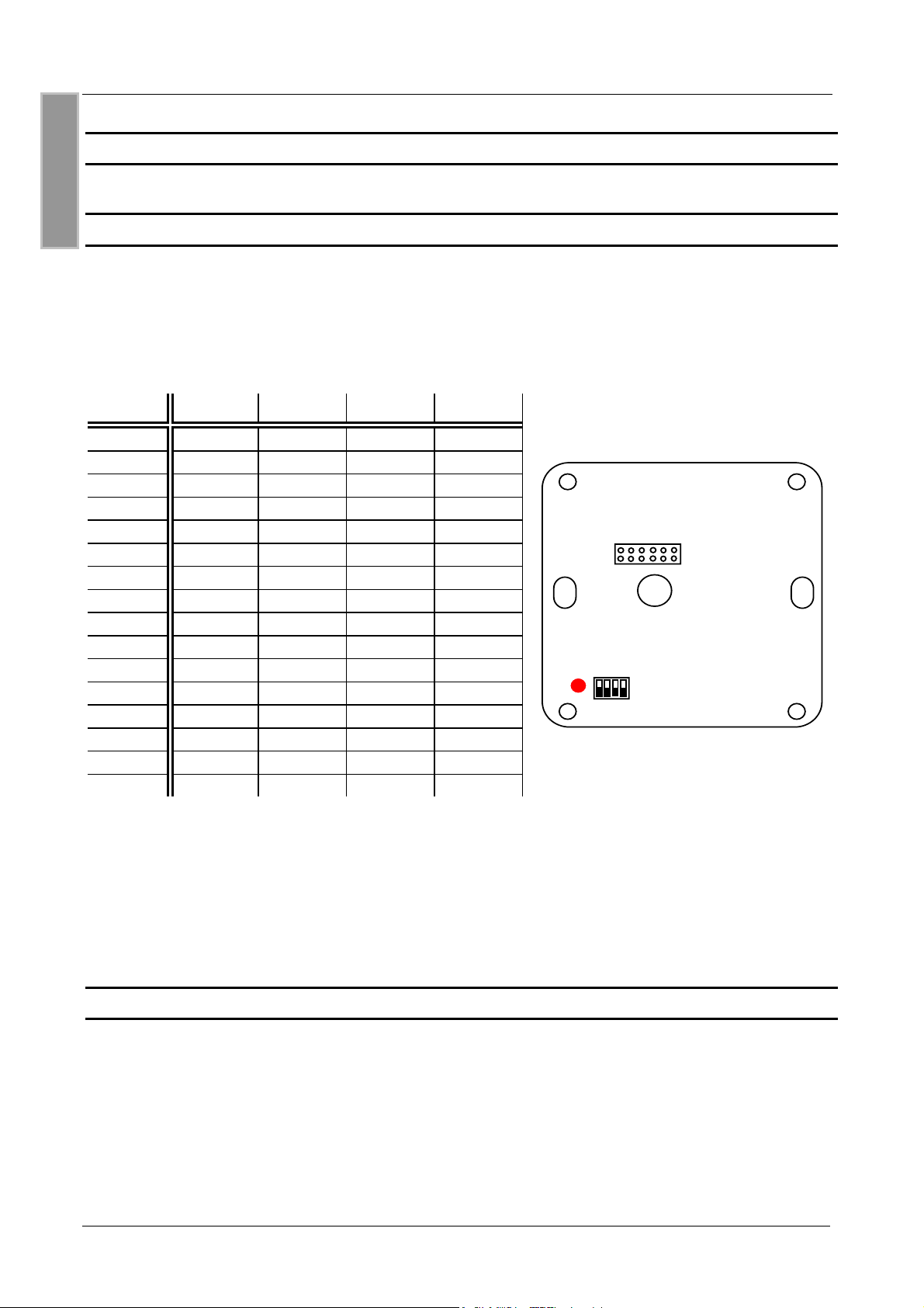
5.2 ID RW02.ABCD-AL/ -BL:
Der Leser ist für die Montage in einem Gehäuse konzipiert. Der Einbauort sollte so gewählt wer-
den, daß bei gewünschter Benutzung des Lesers der Transponder flächenparallel zur Leseranten-
ne geführt werden kann.
Bei der Planung des Einsatzortes muß auf einen räumlichen Abstand von mindestens 3 cm zwi-
schen der Lesersantenne zu leitenden Materialien wie Metallflächen, Metallgitter (Armierung) oder
metallisierte Oberflächen geachtet werden, sonst verringert sich die Lesereichweite.
Bei der Montage der Leiterplatte sollten zur Vermeidung von Schäden an den Leiterbahnen geeig-
nete Maßnahmen (z. B. Kunststoffschrauben, Kunststoffunterlegscheiben) ergriffen werden