VEK MNH Operating Manual v1.3 en
7Description of connections 22
7.1 Power supply........................................................................................................ 22
7.2 Loop inputs .......................................................................................................... 22
7.3 Signal outputs......................................................................................................23
7.3.1 Relay outputs with changeover contact.........................................................23
7.3.2 Open collector outputs ..................................................................................24
8Assembly and electrical installation 25
8.1 Assembly on the DIN rail TS35............................................................................25
8.2 Connecting the power supply ............................................................................. 25
8.3 Connect the relay outputs (versions -R24)......................................................... 26
8.4 Connecting the open collector outputs (versions -O24) ...................................26
8.5 Connecting the induction loops..........................................................................27
9Commissioning 28
10 Description of functions 29
10.1 LED status indicators ..........................................................................................29
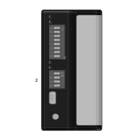
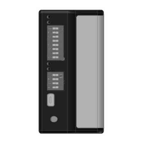
10.2 DIP switch settings .............................................................................................. 30
10.3 Reset button......................................................................................................... 33
10.4 USB interface........................................................................................................33
10.5 Detector Tool service program ...........................................................................33
11 Description of settings 35
11.1 Adjusting sensitivity (switch-on threshold) .......................................................36
11.2 Setting hysteresis (switch-off threshold) ...........................................................37
11.3 Setting loop frequency (frequency step)............................................................ 38
11.4 Setting hold time..................................................................................................39
11.5 Setting output mode (signal type)....................................................................... 39
11.6 Inverting output signal (Signal behaviour)......................................................... 40
11.7 Behaviour in the event of loop error (error mode)............................................. 40
11.8 Assigning an output to a loop (Assignment) ..................................................... 40
11.9 Setting output switching time (impulse time) .................................................... 41
11.10 Setting output times (output time behaviour) .................................................... 41
11.11 Setting direction detection (dual-channel variants)........................................... 42
