FEIMEX FX500 User manual

1
( 4 in 1)
USER MANUAL
LED BAR

2
1.BEFORE YOU BEGIN
What is included
Ø1 x Fixture
Ø1 x Powercable with plug
Ø1 x UserManua
Unpacking Instructions
Immediately upon receiving a fixture, carefully unpack the carton; check the
contents to ensure that all parts are present, and have been received in good
condition. Notify the shipper immediately and retain packing material for
inspection if any parts appear damaged from shipping or the carton itself shows
signs of mishandling. Save the carton and all packing materials. In the event that
a fixture must be returned to the factory, it is important that the fixture be returned
in the originalfactory box andpacking.
AC POWER
This fixture hasan auto-switching switch-modepower supply thatcan
accommodate a widerange of inputvoltages. The only thing necessaryto do
before powering onthe unit isto make surethe line voltageyou are applyingis
within the rangeof accepted voltages.This fixture will accommodate between
100V and 240VAC 50-60Hz. Each lightis connected endto end bythe power
socket “POWER IN”and “POWER OUT”on the light,or use thewaterproof power
cord. Please ensurethe head andthe tail tighteningwhen connect thelights, to
prevent the powerleakage occurred bywater seepage tothe plug.
Help preserve theenvironment! Ensure thatthis product is
recycled at theend of itslife. Your supplier cangive details
of local arrangementsfor the disposalof products.

3
Safety Instructions
!
WARNING!
Please read theseinstructions carefully, which includes
important information aboutthe installation, usageand
maintenance of thisproduct..
The following symbols are used to identify important safety information on the
product and inthis manual:
!!
DANGER!
Safety hazard.
Risk of severe
injury or death
DANGER!
Hazardous
Voltage. Riskof
lethal or severe
electric shock.
WARNING!
Fire hazard
WARNING!
LED light
emission. Risk
of eye injury.
WARNING!
Refer to user
=This light belongsto grade Iprotection device, thereforethe light mustconnect
to the earthexcellently. And thepower connection mustbe operated bythe
professional technician.
=Make sure thatthe working voltagewill not higheror lower thanthe rated value.
=Make sure thatthe cable didn'tbe damage orlacerated by sharp.
=The light mustbe power off when it's standing idle or before clearing.
=The cable mustwith plug, andyou must pullout the cableby handle theplug.
=Please be carefulwhen installing thelighting. Never touchthe bared cable,or
it will causethe deadly electricshock.
=Please use thesuitable and safecable to connectthe light.
=Please never remodelthe light randomly, we willnot take theguarantee for the
faulty and damagewhich caused bydismantle repair or remodelof the
nonprofessional person.
=Maximum ambient temperature40°C. Do notoperate fixture attemperatures
higher than this.
=Never connect thedevice to adimmer pack.
=Do not daisychain power tomore than 8units @ 120Vand 12 units@ 230V.

4
2.INTRODUCTION
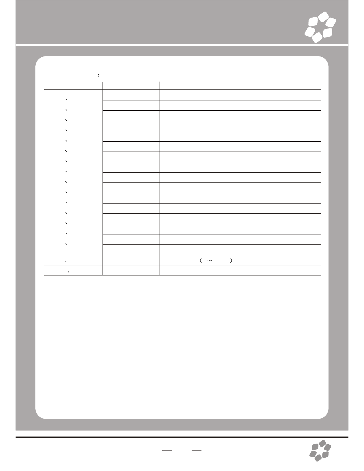
Specifications
lVoltage Rating: AC100V 240V 50-60Hz
lPower Rating: 110W
lLED Quantity: 15X4-in-1(RGBW)
lLED: 380mA
lBeam Angle: 20°/30°/40°(option)
lIngress Protection: IP65/indoor(option)
lProduct Size: 990X120X145mm
lPackage Size:1070X160X170 mm
lN/W:5.7Kg
Features
lRGBW color mixingwith or withoutDMX controller
lspecial effect (minimum 16psc onegroup)
l5 distinct dimmingcurves
lLED display withpassword protection
lTransfer custom programs between fixtures
lOperating Modes: DMX512Connection /Master &Slave...
lDMX Channels: 11/04/06/15/17/21/60 channels

5
Product Overview
POWER IN
POWER IN
DMX IN
POOWER OUT
LED SIGNAL
LED SIGNAL
POWER OUT
DMX OUT
DMX OUT
DMX OUT
Dimensions
INDOOR
OUTDOOR

6
3.SETUP
Installation Requirement
lThis product can be used in a variety of situations, can hang and put on
the ground.
lIf hanging the fixture for over head use,then please followthe below steps.
lPlease choose thesuitable location toput or hangthe light wheninstalling it.
Youmust use the exclusive clamp hanger and screw when hanging it, and
make sure the weight of the light is within limits of the hanger.
lPlease make sure without any flammable objects within 0.5m when
installing the light.
lThe installation should be operated by professional person; any irregular
installation will cause the body injury or equipment damage.
lBlock access belowthe work areaand use suitable and stable platform
when installing or servicing fixture.
Hanging Clamp
Note: sold
separately
Safety Cable
Note: the cablemust be
secured through the heat
sink ventilation
passageway.

7
Connection of DMX Signal Wire
1Please use the fixture controller wire specially when use the DMX512
Controller. Connectthe (male) 3pin connector side of the DMX cable to
the output (female) 3 pinconnector of the first fixture.
2Connect the endof the cable coming fromthe first fixture which willhave
a (male) 3pin connector tothe input connectorof the next fixture
consisting of a (female) 3 pin connector. Then, proceed to connect from
the output asstated above tothe input ofthe following fixture and so on.
3This product can be connected numerous lamps in series without the
need for the signal amplifier; the signal will not be weakened.
DMX IN DMXOUT DMX IN DMXOUT DMX IN DMXOUT
3-PIN TO 5-PIN CONVERSION CHART
Note! If you use a controller with a 5 pin DMX output connector, you will
need to usea 5 pinto 3 pinadapter.
Conductor
Ground/Shield
Data ( -) signal
Data ( +) signal
Do not use
Do not use
3 Pin Female(output)
Pin 1
Pin2
Pin 3
5 Pin Male(Input)
Pin 1
Pin2
Pin 3
Do not use
Do not use
3 PIN TO 5 PIN CONVERSION CHART
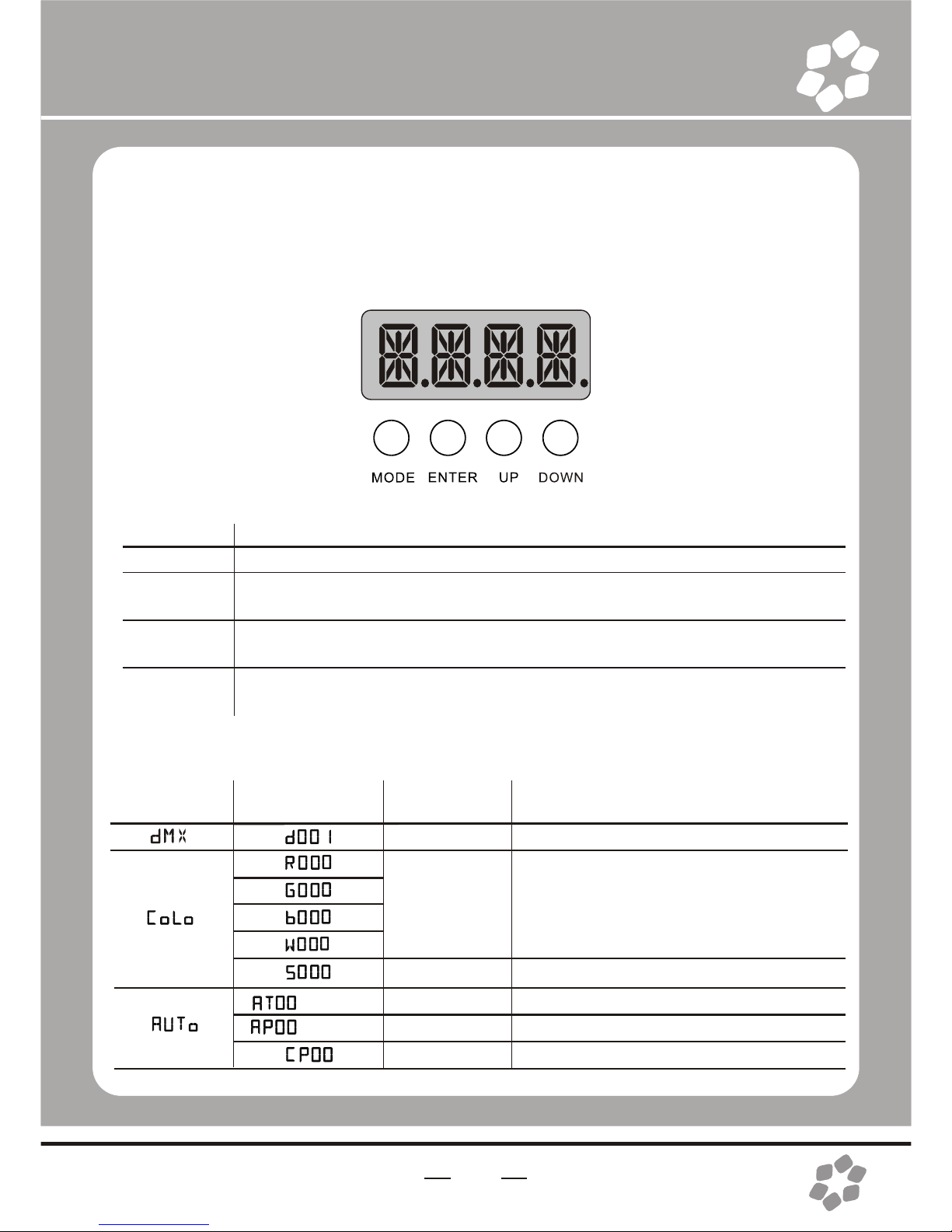
BUTTON
MODE
ENTER
UP
DOWN
FUNCTION
Exits from thecurrent menu or function
Enables the currently displayed menu or sets the currently selected
value in tothe selected function
Navigates upwards through the menu list and increases the numeric
value when ina function
Navigates downwards through the menu list and decreases the numeric
value when ina function
4.OPERATING INSTRUCTIONS
Control Panel Functions
MAIN
FUNCTION
SUB-
FUNCTION SELECTION
001~512
000~255
(0 ~ 100%)
00~20
SP00-20
SP00-20
01~25
INSTRUCTION
Set DMX startaddress
User can combineRED, GREEN, BLUE
and WHITE togenerate a customcolor
Select strobe frequency
auto programs available
combine auto program
combine cartoon effects
Menu Map
8
(01~50)
(01~50)

9
MAIN
FUNCTION
SUB-
FUNCTION SELECTION
11CH
04CH
06CH
15CH
17CH
21CH
60CH
OFF
DIM1/2/3/4
1.00
ON~OFF
01~16
01~16
INSTRUCTION
Slaves
Select 11/04/06/15/17/21/60 channel
setting
"Off" meansselect linear dimming,or
choose dimmer 1-4to control thedimming
speed, dimming 1of the fastestdimming
curves, 4 forthe most slowlydimming curve
Version number
Enables or Disablespassword lockout
amount set ofcombined lights.
number set ofcombined lights
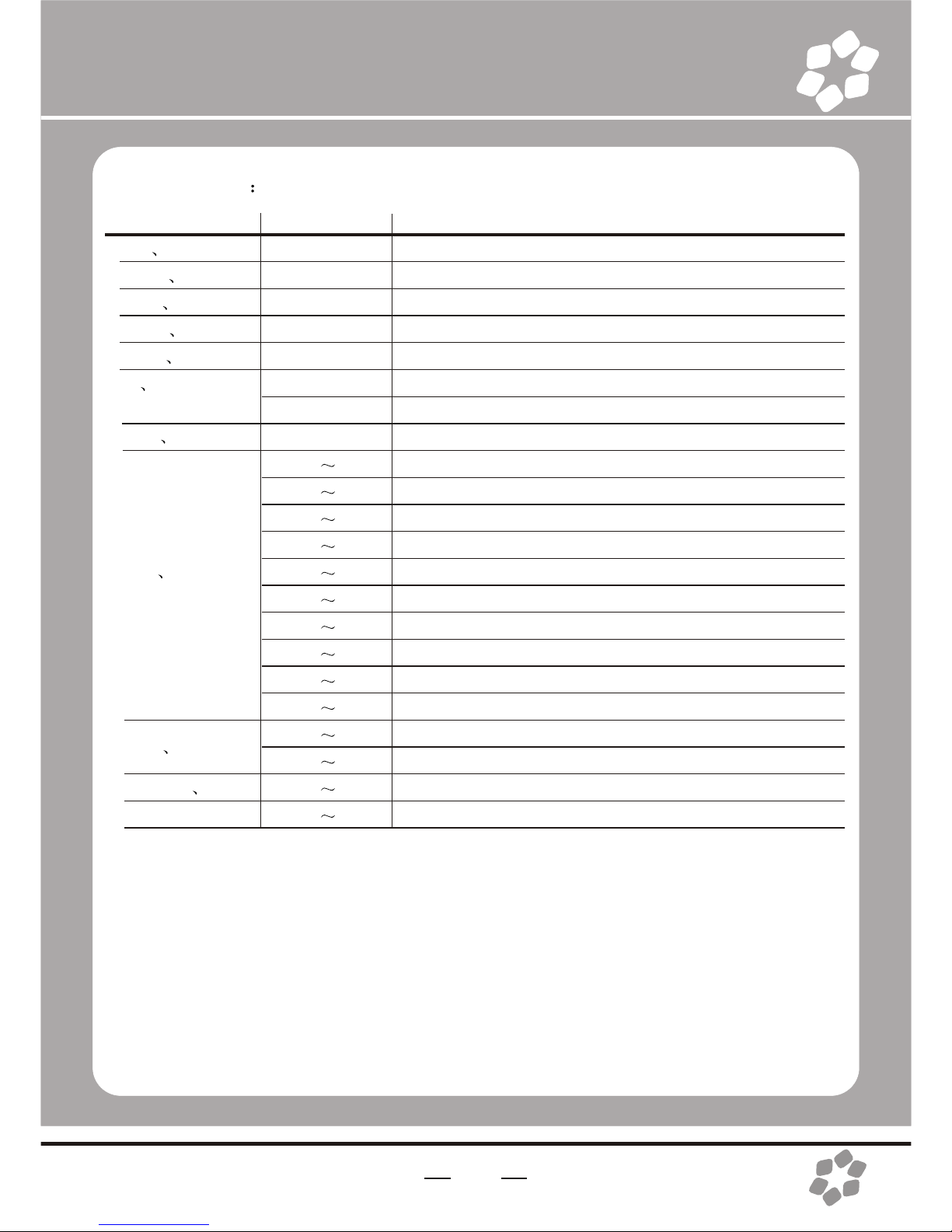
Operating instructions
1 Enable password lock
ÜON / OFF Ü{ENTER}
ON enable lock OFF disable lock
Enable the passwordlock, control panel in the boot or go into standby automatically
take effect, this time tooperate lamps needto enter yourpassword. { MODE UP
MODE DOWN MODE UP MODE DOWN }Ü{ENTER}

10
DMX512 Controller Mode
1 Setting DMX512 Address
Ü001--512
Access control panelfunction by pressingMODE until is displayed.
Press ENTER, addor reduce channelsby pressing UP/DOWNbetween 001 and512.
Press MODE toexit.
3 Setting Channels
Ü11CH/04CH /06CH /15 CH/17 CH /21 CH /60 CH
Access control panelfunction by prekssing MODE until is displayed.
Press ENTER button,select DMX channel by pressing UP/DOWN,
Press MODE toexit.
DMX512 Channel Values
4 channels
Channel
1
2
3
4
Channel
1
2
3
4
5
6
Value
000~255
000~255
000~255
000~255
Value
000~255
000~255
000~255
000~255
000~005
006~255
000~005
006~255
Description
Red
Green
Blue
White
Description
Red
Green
Blue
White
No Function
strobe/auto speed
No Function
AUTO (AT01~50)
6 channels
Channel 6 haspriority over channels 1-5.
When activating theAuto programs, then it is possible to controlthe auto speed by using
Channels 5

11
Channel
1 LED 1
2 LED 2
3 LED 3
4 LED 4
5 LED 5
6 LED 6
7 LED 7
8 LED 8
9 LED 9
10 LED 10
11 LED 11
12 LED 12
13 LED 13
14 LED 14
15 LED 15
Value
000 ~015
016 ~031
032 ~047
048 ~063
064 ~079
080 ~095
096 ~111
112 ~127
128 ~143
144 ~159
160 ~175
176 ~191
192 ~207
208 ~223
224 ~239
240 ~255
Description
No Function
R
G
B
R+G
G+B
R+B
R+G+B
W
R+W
G+W
B+W
R+G+W
G+B+W
R+B+W
R+G+B+W
15 channels
12
Channel
1 LED 1
2 LED 2
3 LED 3
4 LED 4
5 LED 5
6 LED 6
7 LED 7
8 LED 8
9 LED 9
10 LED 10
11 LED 11
12 LED 12
13 LED 13
14 LED 14
15 LED 15
16 strobe
17 FADE
Value
000 ~015
016 ~031
032 ~047
048 ~063
064 ~079
080 ~095
096 ~111
112 ~127
128 ~143
144 ~159
160 ~175
176 ~191
192 ~207
208 ~223
224 ~239
240 ~255
000 ~255
000 ~255
Description
No Function
R
G
B
R+G
G+B
R+B
R+G+B
W
R+W
G+W
B+W
R+G+W
G+B+W
R+B+W
R+G+B+W
strobe 0 20HZ
Dimmer speed(fast toslow)
17 channels
Channel
1 Dimming
2 RED
3 Green
4 Blue
5 white
6 Macro color
control
7 Strobe
8 Module
Selection
9 AUTO
10
11
Value
000~255
000~255
000~255
000~255
000~255
000~009
010~255
000~255
000 004
005 034
035 064
065 094
095 124
125 154
155 184
185 214
215 244
245 255
000 005
006 025
000 255
000 255
Description
0-100%
0-100%
0-100%
0-100%
0-100%
No Function
Macro color control
Strobe(00~20Hz)
#1=ON, #2=ON, #3=ON,
#1=ON
#2=ON
#3=ON
#1=ON, #2=ON
#1=ON, #3=ON
#2=ON, #3=ON
#1=ON, #2=ON, #3=ON,
#1=OFF,#2=OFF, #3=OFF,
Convert to 11CH-2
No Function
AUTO (AT01~50)
Auto speed
Dimmer speed
11 channels
13
MASTER DIMMER
Channels 1 controlsthe intensity of the currently projectedcolor
When the slideris at the highest position (255), then the intensityof the output is at
themaximum.
RED, GREEN BLUE AND WHITE COLOR SELECTION
Channels 2, 3,4and 5 control the intensity ratio of each of the Red, Green, Blue&white
LEDs.
1,2,3,4 and 5 channel can be used in combinationr

14
COLOR MACROS
Channel 6 selectsthe required Color Macro.
Channel 6 haspriority over Channels 2, 3, 4 & 5.
Channel 1 isused to control the intensity of the current ColorMacro.
STROBE
Channel 7 controlsthe strobe of Channels 1 through 6.
Channel 7 haspriority over Channels 2, 3, 4,5 & 6.
Speed of thestrobe is adjustable from 0 to 20 Hz.
MODULE SELECTION
Channel 8 providesindividual control of the three LED modules in eachfixture.
245 ~255 switchto the 11CH-2 mode
AUTO PROGRAMS
Chanel 9 selectsthe preset Auto programs 1~50
When activating theAuto programs, then it is possible to control
the auto speedby using Channels 10
Channel 9 haspriority over channels 2-8.
DIMMER SPEED
Channel 11 is for selecting the dimmer mode and dimmerspeed.
When channel 11 is notactivated, then RGBW and Master
Dimmer are linear.The dimmer modes 1, 2, 3,and 4 are different
speeds of thenonlinear dimming curves

15
Channel
1 LED 1
2 LED 2
3 LED 3
4 LED 4
5 LED 5
6 LED 6
7 LED 7
8 LED 8
9 LED 9
10 LED 10
11 LED 11
12 LED 12
13 LED 13
14 LED 14
15 LED 15
16 Module 1
17 Module 2
18 Module3
19 Module 1 fade
20 Module 2 fade
21 Module 3 fade
Value
000 015
016 031
032 047
048 063
064 079
080 095
096 111
112 127
128 143
144 159
160 175
176 191
192 207
208 223
224 239
240 255
000 005
006~255
000 255
000 255
000 255
Description
No Function
R
G
B
R+G
G+B
R+B
R+G+B
W
R+W
G+W
B+W
R+G+W
G+B+W
R+B+W
R+G+B+W
No Function
strobe 0 20HZ
DIMMER SPEED
DIMMER SPEED
DIMMER SPEED
21 channels
Att Module 1 iscomposed of 1-5LED
Module 2 iscomposed of 6-10 LED
Module 3is composedof 11-15 LED.

Channel
1 LED1
2 LED1
3 LED1
4 LED1
5 LED2
...
57 LED15
58 LED15
59 LED15
60 LED15
Value
000~255
000~255
000~255
000~255
000~255
…
000~255
000~255
000~255
000~255
Description
RED(0~100%)
GREEN(0~100%)
BLUE(0~100%)
WHITE(0~100%)
RED(0~100%)
...
RED(0~100%)
GREEN(0~100%)
BLUE(0~100%)
WHITE(0~100%)
60 channels
16
Master/Slave Control Mode
1 Setting master machine
Access control panelfunction by pressingMODE until is displayed.
Press ENTER, select / / by pressing UP/DOWNbuttons.
Press ENTER, andthen press MODEto exit.
You can choose pre-set programs, therange is o1--50 .
Or you canchoose custom programs, therange is o1--50 .
2 Setting slave machine
Access control panel functionby pressing MODE until is displayed.
Press ENTER,

17
GROUP WORKING
1 Amount set ofcombined lights.
Access control panelfunction by pressing MODE until COMP is displayed
Press ENTER, select C.SUM by pressing UP/DOWN buttons.
Press ENTER,Amount set ofcombined lights. bypressing UP/DOWN between01 and 16
Press MODE toexit.
2 Number set ofcombined lights
Access control panelfunction by pressing MODE until COMP is displayed
Press ENTER, select C.ID by pressing UP/DOWN buttons.
Press ENTER,Amount set ofcombined lights. bypressing UP/DOWN between01 and 16
Press MODE toexit.
Att: the numberof the lightcould not bigger than the amount of the combined lights
3 Setting master machine
Access control panelfunction by pressing MODE until AUTO is displayed.
Press ENTER, select AT AP or CP by pressing UP/DOWNbuttons.
Setting slave machine
Access control panelfunction by pressingMODE until SLAV is displayed.
Press ENTER,
12345678910 11 12 13 14 15 16

Channel
1 Module 1
2 Module 2
3 Module 3
4
5
6
7
8 Mode selection
9
10
11
18
GROUP WORKING (DMX512 MODE)
11CH-2
Value
000 015
016 031
032 047
048 063
064 079
080 095
096 111
112 127
128 143
144 159
160 175
176 191
192 207
208 223
224 239
240 255
000 005
006 255
000 005
006 255
000 009
010 255
000 255
000 244
245 255
000 005
006 255
000 255
000 255
Description
No Function
R
G
B
R+G
G+B
R+B
R+G+B
W
R+W
G+W
B+W
R+G+W
G+B+W
R+B+W
R+G+B+W
No Function
strobe 0 20HZ
No Function
combine auto program(AP 1~50)
No Function
combine cartoon effects(CP 1~25)
No Function
Convert to 11CH-1
Convert to 11CH-2
No Function
AUTO(AT1~50)
CH5/6/9 auto speed
Dimmer speed

19
Symptom(s)
1 or moreLED's are
not illuminating
Possible Solution(s)
Clean the fixtureregularly to avoidany such failure.This fixture is
convection cooled, whichmeans that ifthe surface iskept clean
and free ofdebris, then propercooling will beallowed to occur
An LED mayhave failed, resulting in an open circuit. In this event,
all of thered, green, or blue in a single module will no longer
illuminate. This does not meanthat all of the LEDs have failed,
but the circuitis wired in series.
An LED mayhave failed, resultingin a shortcircuit. In thisevent, only
the single LEDwhich has failedwill no longerfunction. This does not
mean that allof the LEDshave failed, butthe circuit iswired in series.
-Note: In theevent of LED failure, a replacementLED PCB
assembly may bepurchased directly from Our company
AUTO PROGRAMS
Chanel 5 selectsthe preset combineauto program (AP1~50)
Chanel 6 selectsthe preset combinecartoon effects(CP 1~25)
Chanel 9 selectsthe presetAuto program (AT 1~50)
When activating theAuto programs,then it is possible to control the auto speed
by using Channels10
Channel 9 haspriority over channels2-8.
Channel 5 haspriority over channels2-6.
Channel 6 haspriority over channels2-4.
5. APPENDIX
Service Maintenance Guide

20
Symptom(s)
Breaker/Fuse keeps
blowing
Device has nopower
Fixture is not
responding to DMX
Loss of signal
COLOR-CON
Controller does not
function, or doesnot
function properly
Stand alone
operation
The display isonly
showing: ####
Possible Solution(s)
Check total loadplaced on the electrical circuit
Check for ashort in theelectrical wiring: internaland/or external
Check for poweron Mains
-Note: In theevent of autoswitching transformer failure, theunit
can be sentin for repair; however, a replacement part canbe
ordered directly from Our company
Check Control Panelsettings for correct addressing
Check DMX cables
Check polarity switchsettings on the controller
Check cable connections
Call service technician
-Note: In theevent of Display PCB failure, a replacement PCB
can be ordereddirectly from Our company
Use only DMXcables
Install terminator
Note: Keep DMXcables separated from power cables or black
lights
Make sure connectoris firmly connected to device
This fixture mustbe in the correct mode inorder to properly
respond to theCOLOR-CON controller. The correct mode is
“DMX” in the onboardControl Panel
This fixture hasbuilt-in, automatic programs that may be
triggered from theonboard Control Board
The password lockouthas been enabled. you can usethe
password: { MODE UP MODE DOWN MODE UP
MODE DOWN }
Other manuals for FX500
1
Table of contents
Popular Outdoor Light manuals by other brands

Landscape Forms
Landscape Forms Connect 2.0 installation guide

Lithonia Lighting
Lithonia Lighting TDD LED 2 installation instructions

Fermob
Fermob HOOP L1200 manual

Quoizel
Quoizel GLV8408MB Assembly instruction sheet

SLV Elektronik
SLV Elektronik BRICK LED 16 operating manual

Hornbach
Hornbach 10599892 quick start guide


Philips
Philips ecoMOODS 16907/87/16 Specifications

LIGMAN
LIGMAN GINI 2 GN-30091 installation manual

Philips
Philips Urbanspark BDP301 LED 4M 7043 Mounting instructions

SLV
SLV 1006327 instruction manual

Satco Products
Satco Products NUVO LIGHTING 60/2527 Assembly instruction

LIGMAN
LIGMAN SA-31501-1MS installation manual