Nichia 144 Series User manual

Light Emitting Diode
This document contains tentative information, Nichia may change the contents without notice.
1/12 SP-QR-C2-210575-1
Jul. 9, 2021
Application Note
Assembly Precautions
for the Nichia 144 Series LEDs
Table of contents
・・・・・・・・・・2
・・・・・・・・・・・・・・・・・3
・ ・ ・ ・ 4
・ ・ 5-8
・ ・ ・ ・ ・ ・ ・ ・ ・ ・ ・ ・ 8
・・・・・・・・・9-10
・ ・ ・ ・ ・ ・ ・ ・ 10-11
1. LED Outline Dimensions/Tape Dimensions
2. Handling Precautions
3. Design Recommendations for Optimal Amount of Solder
4. Precautions for Setting Up a Pick-and-Place Machine/Nozzle
5. Precautions When Reflow Soldering
6. Evaluation of the Effect of Solder Volume
7. Evaluation of Self-Alignment Performance
The part number NV4L144AR,NV4W144AR,NV4L144AM,NV4W144AM in this document are the part number of our
products, and do not have any relevance or similarity to other companies' products that may have trademark rights.
Light Emitting Diode
This document contains tentative information, Nichia may change the contents without notice.
2/12 SP-QR-C2-210575-1
Jul. 9, 2021
Assembly Precautions for the Nichia 144 Series LEDs
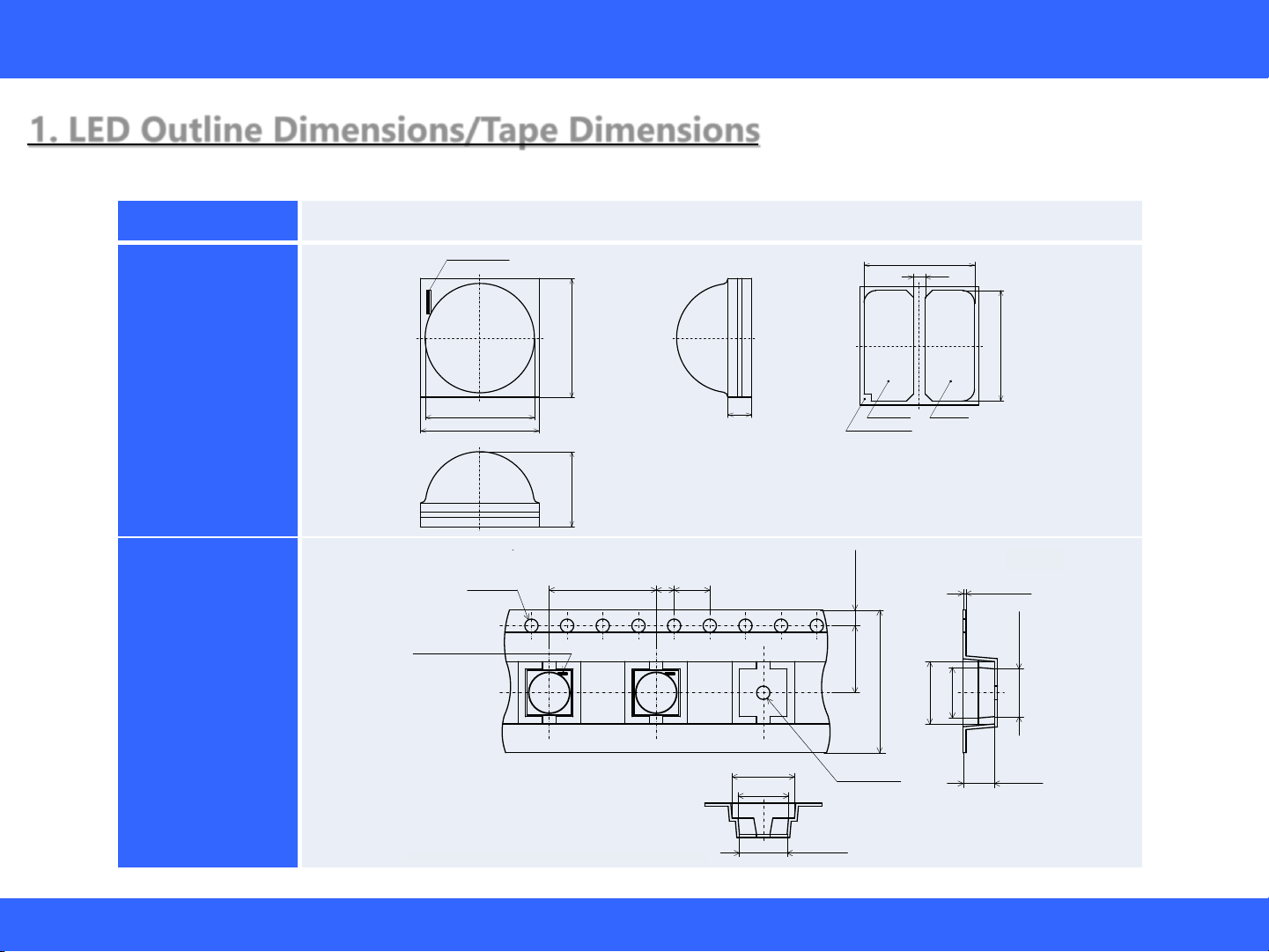
1. LED Outline Dimensions/Tape Dimensions
Table 1. Product Specifications
Part Number NV4L144AR, NV4W144AR, NV4L144AM, NV4W144AM
LED
[unit: mm, Tolerance: ±0.2mm]
Embossed
Carrier
Tape
Reel Size: 1,500 LEDs
[unit: mm]
Nxxx144x
STS-DA7-9282
(単位 Unit: mm)
管理番号 No.
テーピング部 Tape
2±0.1 4±0.1
Φ1.5+0.1
-0
1.75±0.1
7.5±0.1
16+0.3
-0.1
12±0.1
5.35±0.1
0.35±0.05
3.5±0.1
トレーラ部/リーダ部 Trailer and Leader トップカバーテープ
引き出し方向
Embossed Carrier Tape
エンボスキャリアテープ
Top Cover Tape
Feed
Direction
Trailer 160mm MIN(Empty Pockets)
リーダ部最小400mm
Leader without Top Cover Tape 400mm MIN
LED装着部
Loaded Pockets
引き出し部最小100mm(空部)
Leader with Top Cover Tape
100mm MIN(Empty Pocket)
トレーラ部最小160mm(空部)
* 数量は1リールにつき 1500個入りです。
Reel Size: 1500pcs
* 実装作業の中断などでエンボスキャリアテープをリールに巻き取る場合、
エンボスキャリアテープを強く(10N以上)締めないで下さい。
LEDがカバーテープに貼り付く可能性があります。
When the tape is rewound due to work interruptions,
no more than 10N should be applied to
the embossed carrier tape.
The LEDs may stick to the top cover tape.
* JIS C 0806電子部品テーピングに準拠しています。
The tape packing method complies with JIS C 0806
(Packaging of Electronic Components on Continuous Tapes).
リール部 Reel
Φ13±0.2
330±2
ラベル
Label
Φ21±0.8
21.5±1
17.5±0.5
Φ100±1
-0
Φ1.5+0.2
(5.86)
(7)
Cathode Mark
5.35±0.1
(5.86)
(7)
STS-DA7-9306A
NV4L144AM
管理番号 No.
(単位 Unit:mm)
This product complies with RoHS Directive.
本製品はRoHS指令に適合しております。
*
(単位 Unit:mm, 公差 Tolerance:±0.2)
K A
保護素子
Protection Device
0.5
4.65
4.65
AnodeCathode
Cathode Mark
3.15 5
4.6
5
Cathode Mark
1
パッケージ材質
Package Materials
セラミックス
Ceramics
項目 Item 内容 Description
プリコート材質
Pre-coating
Materials
シリコーン樹脂
(拡散剤+蛍光体入り)
Silicone Resin
(with diffuser and phosphor)
レンズ材質
Lens Materials
シリコーン樹脂
Silicone Resin
電極材質
Electrodes Materials
質量
Weight
金メッキ
Au-plated
0.093g(TYP)
Light Emitting Diode
This document contains tentative information, Nichia may change the contents without notice.
3/12 SP-QR-C2-210575-1
Jul. 9, 2021
Assembly Precautions for the Nichia 144 Series LEDs
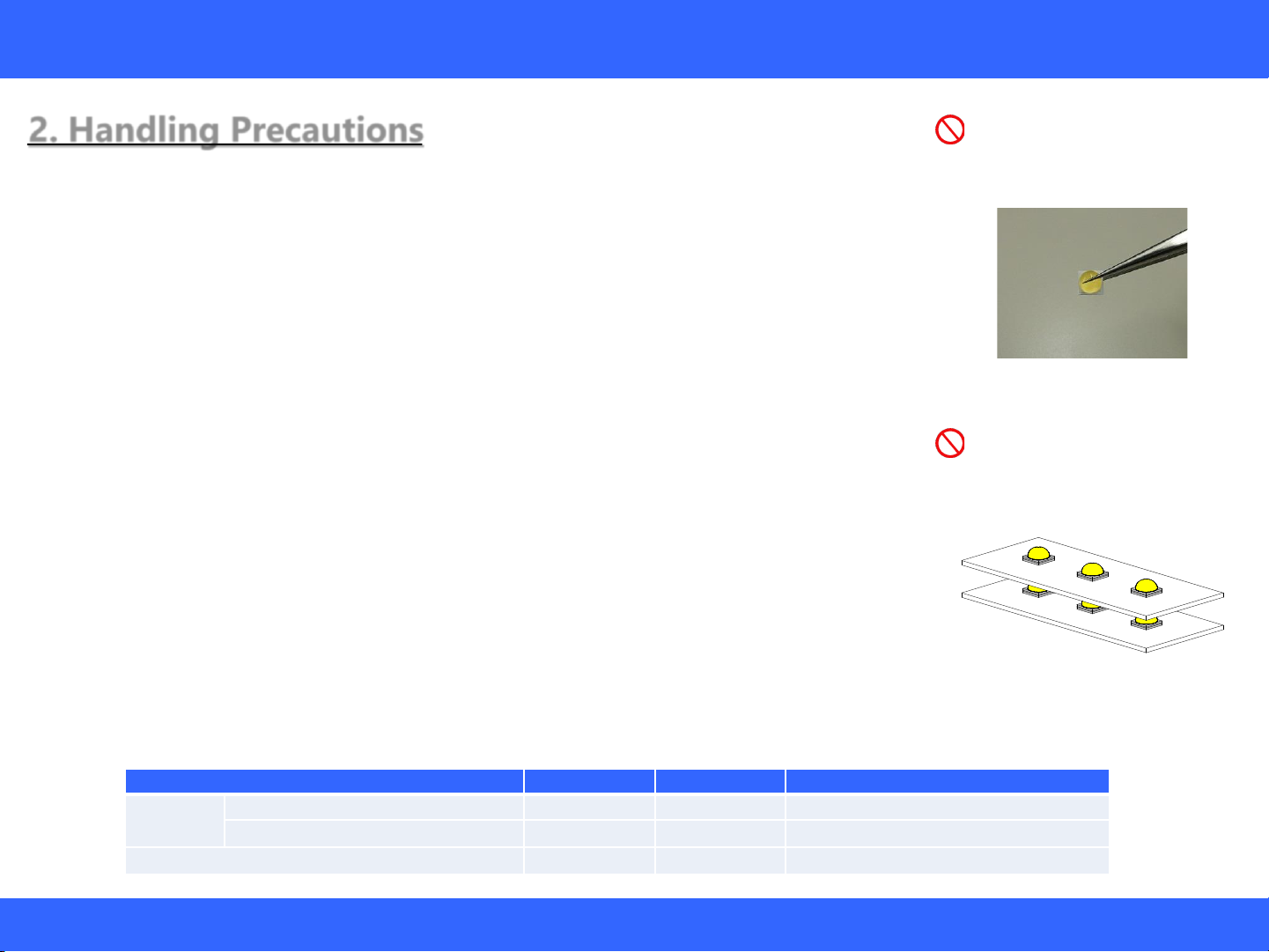
2. Handling Precautions Incorrect
Incorrect
Figure 1. Example of an Improper
Holding Position
Caution: Do not grab/hold the LEDs
with tweezers around the
encapsulating resin.
Figure 2. Example of Improper
Stacking
Caution: Do not stack assembled
PCBs on top of each other.
Handling with bare hands
Do not handle the LEDs with bare hands:
- this may contaminate the LED surface and have an effect on the optical characteristics,
- this may cause the LED to deform and/or the wire to break causing a catastrophic failure (i.e. the LED
not to illuminate),
- the lead frame may cause injuries when the LED is handled with bare hands.
Handling with tweezers
Ensure that when handling the LEDs with tweezers, excessive force is not applied to the LED. Otherwise, it
may cause damage to the resin (e.g. cut, scratch, chip, crack, delamination and deformation) and the
internal connection to fail causing a catastrophic failure (i.e. the LED not to illuminate).
ESD Precautions
LEDs are sensitive to transient excessive voltages (e.g. ESD, lightning surge). If this excessive voltage
occurs in the circuit, it may cause the LED to be damaged causing issues (e.g. the LED to have a reduction
in the radiant flux or not to illuminate [i.e. catastrophic failure]). When handling the LEDs, ensure that
necessary measures have been taken to protect them from transient excess voltages. Refer to the
applicable specification for more details.
Stacking assembled PCBs together
Do not stack assembled PCBs together. Otherwise, it may cause damage to the resin (e.g. cut, scratch,
chip, crack, delamination and deformation) and the internal connection to fail causing a catastrophic
failure (i.e. the LED not to illuminate).
Baking
The storage/packaging requirements for the Nichia 144 Series LEDs are comparable to JEDEC Moisture
Sensitivity Level (MSL) 3 or equivalent. Nichia used IPC/JEDEC STD-020 as a reference to rate the MSL of
this LED. If the “After Opening” storage time has been exceeded or any pink silica gel beads are found,
ensure that the LED are baked before use. Baking should only be done once.
Conditions Temperature Humidity Time
Storage
Before Opening Aluminum Bag
≤ 30°C ≤ 90% RH Within 1 Year from Delivery Date
After Opening Aluminum Bag
≤ 30°C ≤ 70% RH ≤ 168 hours
Baking 65±5°C - ≥24 hours
Table 2. Storage/Baking Conditions
Light Emitting Diode
This document contains tentative information, Nichia may change the contents without notice.
4/12 SP-QR-C2-210575-1
Jul. 9, 2021
Assembly Precautions for the Nichia 144 Series LEDs
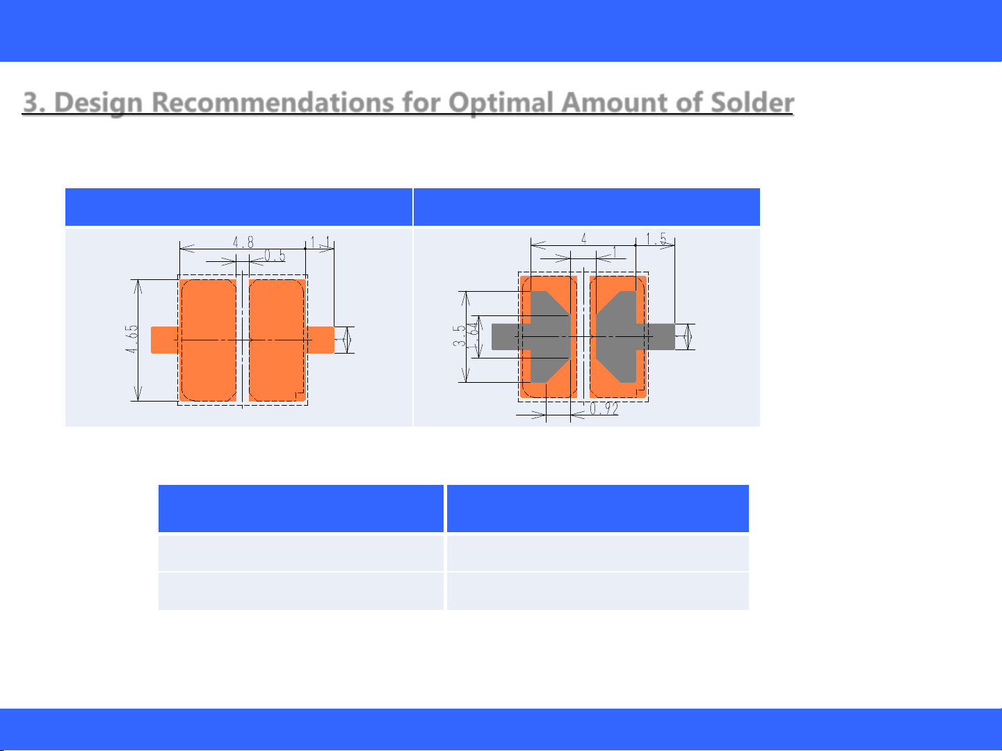
3. Design Recommendations for Optimal Amount of Solder
Soldering Pad Pattern/Metal Solder Stencil Aperture
Table 3. Recommended Soldering Pad Pattern/Metal Solder Stencil Aperture
Table 4. Recommended Solder/Metal Solder Stencil Conditions
Soldering Pad Pattern Stencil Aperture
[unit:mm] [unit:mm]
⋯LED outline
■Soldering Pad Pattern
■Stencil Aperture
Item Recommended
Condition
Solder Stencil Thickness 120 [μm]
Solder Paste Sn-3.0Ag-0.5Cu

Light Emitting Diode
This document contains tentative information, Nichia may change the contents without notice.
5/12 SP-QR-C2-210575-1
Jul. 9, 2021
Assembly Precautions for the Nichia 144 Series LEDs
4. Precautions for Setting Up a Pick-and-Place Machine/Nozzle
Table 5. Cautions/Suggestions for setting up equipment
Item Recommended Conditions/Specifications Cautions/Suggestions
Pick-and-place machine1Modular mounter
Pick-and-place nozzle Specially designed nozzle
(see Figure 3)
See “Pick-and-Place Nozzle” on
Page 6 for the details.
Tape-and-reel feeder
Electrical (motorized) feeder
Tape width: 16mm
Feed length: 12mm
See “Tape-and-Reel Feeder” on
Page 6 for the details.
Nozzle height for pick-up
operations
The contact surface of the nozzle head for pick
operations should be adjusted to 1.7mm below the edge
of the embossed carrier tape pocket.
See “Recommended Nozzle Height
for Pick-up Operations” on Page 7
for the details.
Nozzle height for placement
operations (i.e. placement depth) 0.2mm for placement depth
See “Recommended Nozzle Height
for Placement Operations
(Placement Depth)” on Page 7 for
the details.
Imaging-based Automatic
Inspection
Using the electrode as a reference is recommended to
locate the center of the LED.
See "Imaging-based Automatic
Inspection" on Page 8 for the
details.
Note:
1The recommended conditions/specifications above have been determined under the following verification conditions:
Pick-and-place machine (modular mounter):
- YS100 High-Speed General-Purpose Modular (manufactured by Yamaha Motor Co., Ltd.)
Light Emitting Diode
This document contains tentative information, Nichia may change the contents without notice.
6/12 SP-QR-C2-210575-1
Jul. 9, 2021
Assembly Precautions for the Nichia 144 Series LEDs
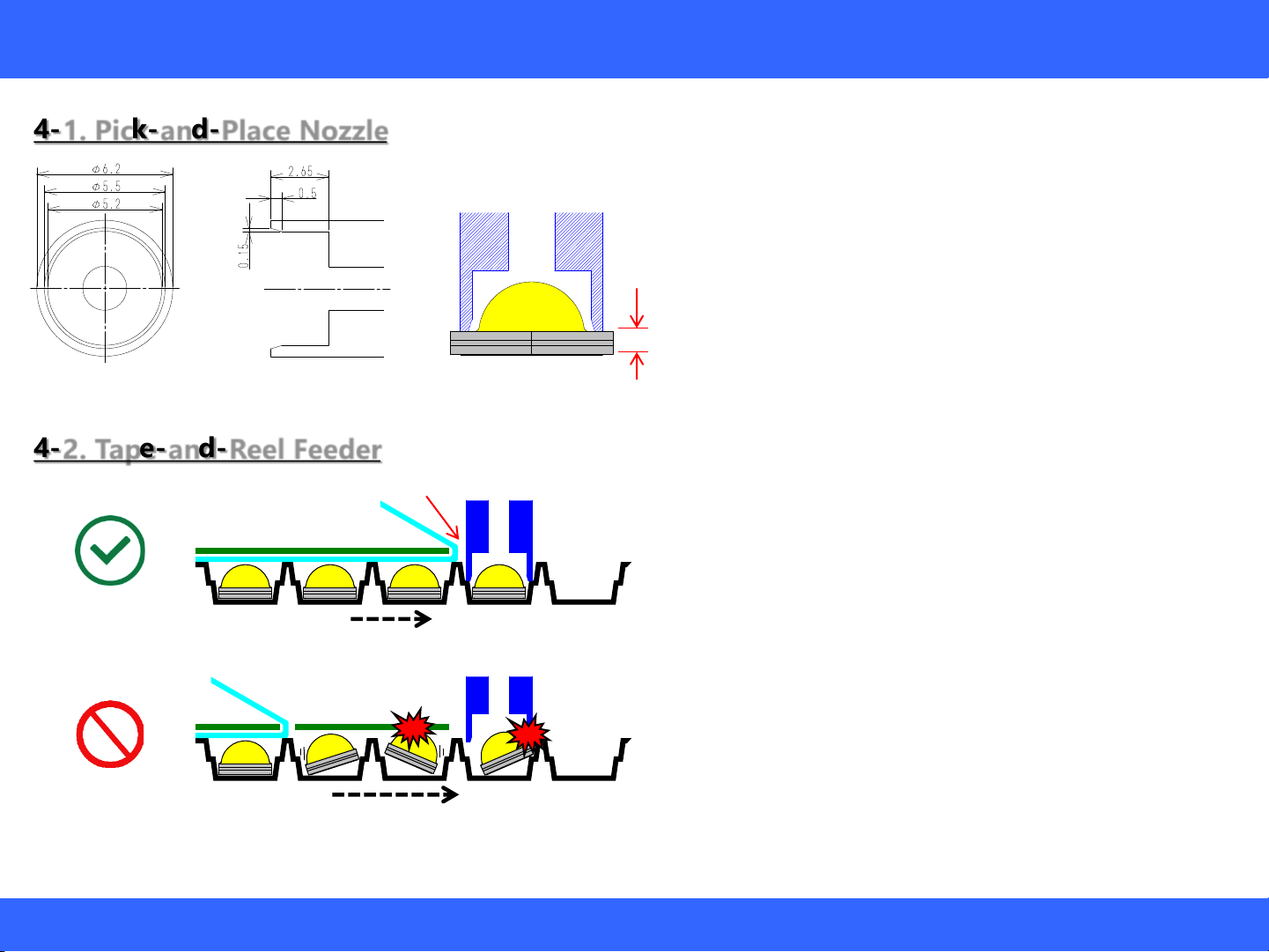
4-2. Tape-and-Reel Feeder
4-1. Pick-and-Place Nozzle
[Unit: mm]
Figure 3. Recommended Nozzle
Dimensions
Figure 4. part Height
Correct
Incorrect
Figure 5. Examples of Correct/Incorrect Top Cover Tape Removal Positions
1.0mm
•The nozzle must not have any direct contact with
the encapsulating resin.
•The nozzle touches on the top of LED substrate.
(see Fig. 4)
Therefore input value of the Part Height should
be 1.0mm.
•Tape width:16mm / Feed length:12mm
•The chosen tape feeder should be one that has a
slower feeding speed (e.g. electrical feeders).
•The recommended tape removal position is right
next to where the pick-and-place nozzle picks up
the LEDs to prevent the LEDs from tilting within the
tape pocket and becoming damaged by the feeder
shutter and/or nozzle.
Tape Removal Position
Slower feeding speed = Less vibration
LED position stays stable.
Faster feeding speed = More vibration
LED tilts within the tape pocket.

Light Emitting Diode
This document contains tentative information, Nichia may change the contents without notice.
7/12 SP-QR-C2-210575-1
Jul. 9, 2021
Assembly Precautions for the Nichia 144 Series LEDs
4-4. Recommended Nozzle Height for Placement
Operations (Placement Depth)
4-3. Recommended Nozzle Height for
Pick-up Operations
Figure 6. Recommended Nozzle Height for Pick-up Operations
Figure 7. Recommended Nozzle Height for Placement (Placement Depth)
Pickup Point
1.7mm from
the top of the
carrier tape
Pick-and-Place
Nozzle
Carrier Tape
Press
0.2[mm]
PCB
Pick-and-Place
Nozzle
•After the LED is mounted onto solder paste on the PCB,
the nozzle should further press the LED 0.2mm into the
PCB.
•Pick-and-place nozzle should be 1.7mm inside from the top of
carrier tape to pick up the LED. (see Fig. 6)
•Some LED mounters may not be stabilize the operation. In
that case, adjusting the height for LED pickup is needed until
the operation is stabilized.
☞If the pickup point is higher than the recommended
point, the LED may tilt, and poor suction may occur
which will cause a suction error.(e.g. diagonal
positioning within the nozzle)
☞If the pickup point is lower than the recommended
point, poor suction may occur due to carrier tape
deformation.
☞If the press force is too weak, assembly failure may
occur since the LED may float on top of the PCB or it
may not separate from the nozzle.
☞If press force is too strong, LED may receive
excessive stress which may cause the LED to be
damaged.
Light Emitting Diode
This document contains tentative information, Nichia may change the contents without notice.
8/12 SP-QR-C2-210575-1
Jul. 9, 2021
Assembly Precautions for the Nichia 144 Series LEDs
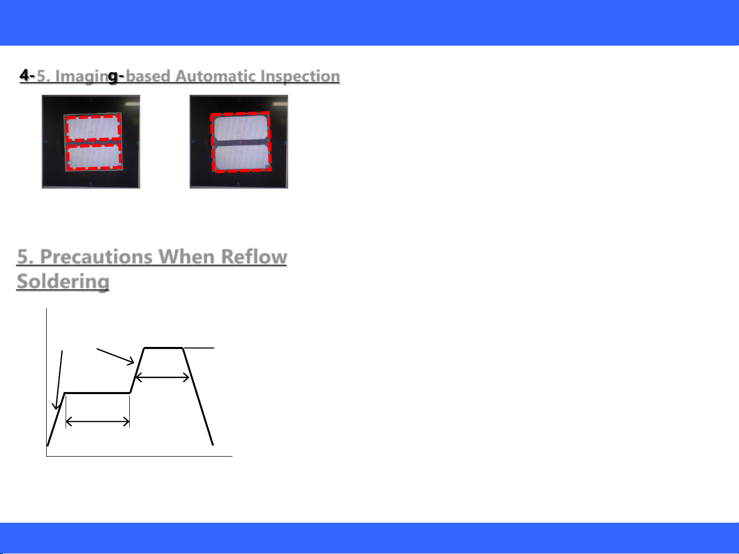
4-5. Imaging-based Automatic Inspection
5. Precautions When Reflow
Soldering
Figure 8. Electrical Pads
(Recommended)
Figure 10. Recommended Reflow Soldering
Condition (Lead-free Solder)
120sec Max
Pre-heat
180 to 200°C
260°CMax
10sec Max
60sec Max
Above 220°C
1 to 5°C per sec
•Reflow soldering must not be performed more than twice.
•Using the recommended reflow soldering conditions (See Figure 10 to
the left) as a reference, modify if necessary, the recommended reflow
conditions specified by the manufacturer of the solder paste being used.
Note:
To ensure that these reflow conditions have no negative effect on the
LEDs, perform sufficient verification prior to use.
•When cooling the LEDs from the peak temperature a gradual cooling
slope is recommended; do not cool the LEDs rapidly.
•During reflow soldering, the heat and atmosphere in the reflow oven may
cause the optical characteristics to degrade. In particular, reflow soldering
performed with an air atmosphere may have a greater negative effect on
the optical characteristics than if a nitrogen atmosphere is used; Nichia
recommends using a nitrogen reflow atmosphere.
•Using image recognition and adjusting the pickup
position for each LED should be implemented to
maintain assembly accuracy. It is recommended to
have the adjustment based on the position of the
electrical pads for higher assembly accuracy.
Figure 9. Outline

Light Emitting Diode
This document contains tentative information, Nichia may change the contents without notice.
9/12 SP-QR-C2-210575-1
Jul. 9, 2021
Assembly Precautions for the Nichia 144 Series LEDs
6. Evaluation of the Effect of Solder Volume
The amount of solder paste was evaluated and compared with the recommended solder stencil conditions (section3).
Lighting, wettability, solder ball and floating were inspected after the reflow process.
Table 6. Evaluation Result(Lighting Check, Solder Wettability, Solder Ball)
Stencil
Aperture Rate
※Stencil Aperture Area
/Electrode Area
30% 50% (Recommend) 70%
Stencil Thickness
100μm
Lighting check
OK Lighting check
OK Lighting check
OK
Solder Ball
0/24 pcs Solder Ball
0/24 pcs Solder Ball
0/24 pcs
120μm
(Recommend)
Lighting check
OK Lighting check
OK Lighting check
OK
Solder Ball
0/24 pcs Solder Ball
0/24 pcs Solder Ball
2/24 pcs
150μm
Lighting check
OK Lighting check
OK Lighting check
OK
Solder Ball
0/24 pcs Solder Ball
2/24 pcs Solder Ball
6/24 pcs
•Solder wettability performance was good enough to light the LED in all conditions. However,
solder ball occurrence was increased if solder paste volume (area, thickness) is increased.

Light Emitting Diode
This document contains tentative information, Nichia may change the contents without notice.
10/12 SP-QR-C2-210575-1
Jul. 9, 2021
Assembly Precautions for the Nichia 144 Series LEDs
•Amount of tilt (avg.): 60μm
Angle of incline: around 0.7 degree
Solder volume does not affect to the amount of
tilt and angle of incline.
Figure 11. Evaluation Result (LED Lifting)
※n=24pcs/each condition
Max.
Figure 12. How to Measure the Amount of LED Tilt
Min.
0
20
40
60
80
100
120
140
Amount of Floating [μm]
100μm 120μm 150μm
Stencil Thickness
Aperture Rate:
30%
Aperture Rate:
50%
Aperture Rate:
70%
Average
①x:+0.2mm
y:+0.2mm ② θ:+10°
Table 7. Evaluate Conditions
+Pad pattern Position
+Mounted Position
7. Evaluation of Self-
Alignment Performance
Self-alignment was evaluated under the condition
shown in table 7 with the solder conditions shown
in section 6.
Amount of self-alignment was confirmed from
center of the land pattern.
Amount of LED Tilt (mm) = max. –min.

Light Emitting Diode
This document contains tentative information, Nichia may change the contents without notice.
11/12 SP-QR-C2-210575-1
Jul. 9, 2021
Assembly Precautions for the Nichia 144 Series LEDs
-0.3
-0.2
-0.1
0
0.1
0.2
0.3
-0.3 -0.2 -0.1 0 0.1 0.2 0.3
⊿y [mm]
⊿x [mm]
Stencil Thickness:100μm
Aperture Rate:30%
Aperture Rate:50%
Aperture Rate:70%
Mount Position
-0.3
-0.2
-0.1
0
0.1
0.2
0.3
-0.3 -0.2 -0.1 0 0.1 0.2 0.3
⊿y [mm]
⊿x [mm]
Stencil Thickness:120μm
Aperture Rate:30%
Aperture Rate:50%
Aperture Rate:70%
Mount Position
-0.3
-0.2
-0.1
0
0.1
0.2
0.3
-0.3 -0.2 -0.1 0 0.1 0.2 0.3
⊿y [mm]
⊿x [mm]
Stencil Thickness:150μm
Aperture Rate:30%
Aperture Rate:50%
Aperture Rate:70%
Mount Position
•Aperture ratio: 50%, stencil thickness: 120μm
(Recommended conditions)
•No abnormality in the self-alignment
•Self-alignment could be acceptable if the mounting
accuracy are x,y <200μm and θ<10o.
•Aperture ratio: 30%, stencil thickness: 100μm
•Some LEDs have issue for the self-alignment.
•If the solder volume is poor, LED may not be mounted
to the proper position that causes misalignment of
LED.
Figure 13. Evaluation Result (①x:+0.2mm,y:+0.2mm)
※n=24pcs/condition
Figure 14. Evaluation Result (② θ:+10°)
※n=24pcs/each condition
-0.8
-0.4
0.0
0.4
0.8
1.2
1.6
2.0
Angle[°]
100μm 120μm 150μm
Stencil Thickness
Mount Angle:10°
Aperture Rate:30%
Aperture Rate:50%
Aperture Rate:70%
Average

Light Emitting Diode
This document contains tentative information, Nichia may change the contents without notice.
12/12 SP-QR-C2-210575-1
Jul. 9, 2021
Disclaimer
This application note is a controlled document of Nichia Corporation (Nichia) published to provide technical information/data for
reference purposes only. By using this application note, the user agrees to the following:
•This application note has been prepared solely for reference on the subject matters incorporated within it and Nichia makes no
guarantee that customers will see the same results for their chosen application.
•The information/data contained herein are only typical examples of performances and/or applications for the product. Nichia
does not provide any guarantees or grant any license under or immunity from any intellectual property rights or other rights
held by Nichia or third parties.
•Nichia makes no representation or warranty, express or implied, as to the accuracy, completeness or usefulness of any
information contained herein. In addition, Nichia shall not be liable for any damages or losses arising out of exploiting, using,
or downloading or otherwise this document, or any other acts associated with this document.
•The content of this application note may be changed without any prior or subsequent notice.
•Copyrights and all other rights regarding the content of this document are reserved by Nichia or the right holders who have
permitted Nichia to use the content. Without prior written consent of Nichia, republication, reproduction, and/or redistribution
of the content of this document in any form or by any means, whether in whole or in part, including modifications or derivative
works hereof, is strictly prohibited.
NICHIA CORPORATION
491 Oka, Kaminaka-Cho, Anan-Shi,
TOKUSHIMA 774-8601, JAPAN
Phone: +81-884-22-2311 Fax: +81-884-21-0148
http://www.nichia.co.jp
Assembly Precautions for the Nichia 144 Series LEDs
This manual suits for next models
4
Table of contents
Popular Outdoor Light manuals by other brands


pdlux
pdlux PD-PIR69 instructions

Maximus
Maximus Smart Security Light instruction manual

Cree
Cree NTW Series installation instructions

CristalRecord
CristalRecord NASSIRA 60W quick start guide

Tamlite
Tamlite CITY RL Installation & operating instructions

Clarke
Clarke SAL100B Assembly & operating instructions