Fein GRIT GIM User manual

3 94 10 014 000 • 06.07 • Abbildungen unverbindlich. Technische Änderungen vorbehalten. © C. E.FEIN GmbH • Printed in Germany.
FEIN Service
Kundendienst
C. E. FEIN GmbH
Feinstraße 3
D-72820 Sonnenbühl
Telefon 0 71 28/3 88 163
Telefax 0 71 28/3 88 169
Firmensitz
C. E. FEIN GmbH
Hans-Fein-Straße 81
D-73529 Schwäbisch Gmünd/Bargau
www.fein.com
Vertrieb
C. E. FEIN GmbH
Leuschnerstraße 43
D-70176 Stuttgart
Telefon 07 11/66 65-0
Telefax 07 11/66 65-249
98/37/EU, 89/336/EU, 73/23/EU.
Jøm Toft
Manager
Steen Mølsted
Quality Manager
GRIT GIM
GIM - Titel Seite 1 Freitag, 18. August 2006 8:39 08

2
Deutsch ____________ Gebrauchsanleitung________________
English _____________ Instruction manual ________________
Français ____________ Notice d’utilisation ________________
Italiano _____________ Libretto delle Istruzioni per l’uso_______
Nederlands __________ Gebruiksaanwi zing ________________
Español_____________ Instrucciones de uso _______________
Português ___________ Instrução de serviço _______________
EÏÏËÓÈο ____________ √‰ËÁ›Â˜ ¯ÂÈÚÈÛÌÔ‡ _________________
Dansk ______________ Brugsanvisning ___________________
Norsk ______________ Bruksanvisning ___________________
Svenska ____________ Bruksanvisning ___________________
Suomi ______________ Käyttöoh e ______________________
Magyar _____________ Használati útmutató _______________
âesky______________ Návod k pouÏití___________________
Slovensky ___________ Návod na pouÏívanie _______________
Polski______________ Instruk ja obs∏ugi _________________
На русском языке ___ Руководство по эксплуатации __
_____________
____________________
6
9
12
15
18
21
24
27
30
33
36
39
42
45
48
51
54
57
3 94 10 014 000 - Buch Seite 2 Mittwoch, 16. August 2006 1:26 13

100,00 mm
3
123
6
5
4
1
23
78
12
13
2
1
910
11
8a
3 94 10 014 000 - Buch Seite 3 Mittwoch, 16. August 2006 1:26 13

4
19
15
14
16 17
18
20
3
3 94 10 014 000 - Buch Seite 4 Mittwoch, 16. August 2006 1:26 13

5
45
67
89
11
10 16
21
22
23
19
3 94 10 014 000 - Buch Seite 5 Mittwoch, 16. August 2006 1:26 13

6
GIM
DE
Verwendete Symbole, Abkürzungen
und Begriffe.
Die in dieser Gebrauchsanleitung und ggf. auf
de Gerät verwendeten Sy bole dienen dazu,
Ihre Auf erksa keit auf ögliche Gefährdun-
gen bei der Arbeit it diese Gerät zu lenken.
Zu Ihrer Sicherheit.
Verwenden Sie dieses Fahrgestell nicht,
bevor Sie diese Gebrauchsanleitung gründ-
lich gelesen und vollständig verstanden
haben, einschließlich der Abbildungen,
Spezifikationen und Sicherheitsregeln.
Lesen und beachten Sie die Gebrauchsan-
leitung der Maschine, die auf dieses Fahrge-
stell ontiert werden soll.
Diese Gebrauchsanleitung zu späteren
Gebrauch aufbewahren und bei einer Weiter-
gabe oder Veräußerung der Maschine überrei-
chen.
Verwenden Sie zur Montage der Maschine auf dem
Fahrgestell das passende Befestigungsmaterial.
Eine fehlerhafte Montage kann dazu führen, dass
sich die Maschine während des Arbeitsvorganges
vo Fahrgestell löst und schwere Unfälle verur-
sacht.
Stellen Sie vor dem Einschalten sicher, dass alle
Spannhebel am Fahrgestell gut festgezogen sind.
Senkt sich die Maschine während des Arbeits-
vorganges plötzlich ab, kann dies zu schweren
Unfällen führen.
Benutzen Sie eine Schutzbrille.
Die Schutz-
brille uss sich eignen, die bei unter-
schiedlichen Arbeiten weggeschleuderten
Partikel abzuwehren.
Tragen Sie zusätzliche Schutzausrüstung wie
Sicherheitsschuhe und Schutzhandschuhe.
Es besteht Verletzungsgefahr durch unbe-
absichtigtes Berühren des Schleifbandes
während des Arbeitsvorganges.
Arbeiten Sie nur auf waagrechten Flächen.
Auf
schrägen Flächen kann die Maschine außer Kon-
trolle geraten.
Das Verlängerungskabel während des Arbeitsvor-
ganges immer von der Arbeitsstelle wegführen.
Wird das Netzkabel überfahren, gequetscht
oder beschädigt, besteht die Gefahr eines elek-
trischen Schlags!
Bei Wartungs- Montage und Einstellarbeiten den
Netzstecker ziehen!
Wird die Maschine unbeab-
sichtigt eingeschaltet, kann dies zu Unfällen füh-
ren.
Auf einen Blick.
1 Befestigungsschraube
2 Unterlegscheibe
3 Rad
4 Achse
5 Feststellschraube, Achse
6 Auflagefläche
7 Befestigungsschrauben für Halteplatte
8 Schraube
8a Schraube (Bandschleifer)
9 Halteplatte
10 Halteschaft
11 Feststellschraube für Lenkstangeneinstellung
12 Lenkstange
13 Befestigungsschrauben für Bandschleifer (4x)
14 Sicherheitsschalter
15 Ein-/Ausschalter
16 Kurbel für Bandschleifer-Höheneinstellung
17 Kabelbinder
18 Elektrischer Schaltkasten
19 Sterndrehschraube für Paralleleinstellung
20 Feststellschraube
21 Schraube für Tiefenanschlag
22 Schraube für Höhenanschlag
23 Kurbel für Hubkrafteinstellung
Symbol Begriff, Bedeutung
➤
Aktion
Doku entation lesen
Allge eines Gebotszeichen
Warnung vor Gefahr
3 94 10 014 000 - Buch Seite 6 Mittwoch, 16. August 2006 1:26 13

GIM
7
DE
Bestimmung der Maschine.
Das Fahrgestell ist in Verbindung it GRIT
Schleif aschinen GI 75/150 zu Schleifen von
Bodenflächen besti t.
Montageanweisungen.
Fahrwerk montieren (Bild 1).
➤
Stecken Sie die Achse (4) durch das Achs-
rohr. Befestigen Sie die Räder (3) it den
Schrauben (1) und Unterlegscheiben (2) an
der Achse.
➤
Fixieren Sie die Achse (4) it der Feststell-
schraube (5) so, dass sich zwischen Radnabe
und Achsrohr ein Abstand von ca. 100
ergibt.
Bandschleifer auf Fahrgestell montieren
(Bild 2).
➤
Entfernen Sie a Bandschleifer den Späne-
kasten, den Schleiftisch, sowie die entspre-
chenden Schrauben (siehe
Gebrauchsanweisung Bandschleifer).
Wegen erhöhter Unfallgefahr müssen die
folgenden Arbeitsschritte von mehreren
Personen durchgeführt werden:
➤
Öffnen und entfernen Sie das Seitenteil des
Bandschleifers.
➤
Legen Sie den Bandschleifer it der Kopf-
seite auf den Boden. Verwenden Sie zur
Ver eidung von Kratzern oder Beschädi-
gungen eine geeignete Unterlage.
➤
Setzen Sie das Fahrgestell auf den Band-
schleifer auf.
➤
Richten Sie das Fahrgestell über den Bohrun-
gen aus. Befestigen Sie das Fahrgestell it
den Schrauben (13) a Bandschleifer.
➤
Stellen Sie die gesa te Einheit auf die
Räder (3).
➤
Entfernen Sie die Schraube (8a) a Band-
schleifer.
➤
Montieren Sie die Halteplatte (9) it den
Schrauben (7) und (8) an den vorderen Teil
des Bandschleifers.
➤
Schieben Sie die Lenkstange (12) auf den
Halteschaft (10) und sichern Sie diese it
den vier Feststellschrauben (11) des Halte-
bügels.
Elektroanschluss.
Stellen Sie vor dem Anschluss an das
Stromnetz sicher, dass der Bandschleifer
ausgeschaltet ist (Taste „0“ am Sicherheits-
schalter muss gedrückt sein!).
➤
Schließen Sie den Bandschleifer an den
Schaltkasten (18) an und befestigen Sie das
Netzkabel it den Kabelbindern (17) an der
Lenkstange (12).
➤
Schließen Sie den Schaltkasten (18) it
eine Verlängerungskabel an das Stro netz
an.
Einstellungen.
Ziehen Sie vor allen Arbeiten an der
Maschine den Stecker aus der Steckdose.
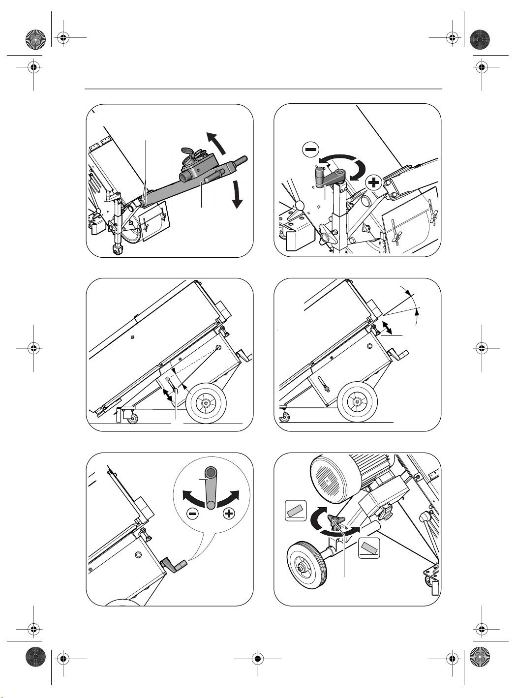
Lenkstange einstellen (Bilder 3/4).
➤
Die vier Schrauben (11) lösen und die Lenk-
stange auf die gewünschte Arbeitshöhe ein-
stellen. Alle Schrauben in dieser Position
festziehen.
Schleifabtrag einstellen (Bilder 3/5).
➤Stellen Sie den Bandschleifer it der Stern-
drehschraube (20) ungefähr auf Arbeitshöhe
ein.
➤Stellen Sie it der Kurbel (16) den Abstand
zwischen Schleifband und Oberfläche ein.
Der Schleifabtrag kann auch während des
Arbeitsvorganges reguliert werden.
Tiefenanschlag einstellen (Bild 6).
➤Die Schraube (21) lösen.
➤Mit der Kurbel (16) den Bandschleifer auf
den Schleifabtrag einstellen der axi al
erreicht werden soll.
➤Den Tiefenanschlag it der Schraube (21) in
dieser Position fixieren.
Höhenanschlag einstellen (Bild 7).
➤Die Lenkstange nach oben schwenken, so
dass sich der Bandschleifer nach oben
bewegt.
➤Mit der Schraube (22) kann die gewünschte
Schwenkhöhe eingestellt werden.
3 94 10 014 000 - Buch Seite 7 Mittwoch, 16. August 2006 1:26 13

8
GIM
DE
Hubkraft einstellen (Bild 8).
➤Mit der Kurbel (23) kann die erforderliche
Hubraft eingestellt werden.
➤Die Hubkraft so einstellen, dass der Band-
schleifer leichtgängig abgesenkt werden
kann und bei Anheben oder in Arbeitspau-
sen selbsttätig in der oberen Position gehal-
ten wird.
Parallelität einstellen (Bild 9).
Für einen gleich äßigen Schleifabtrag ist es
erforderlich, dass das Schleifband parallel zur
Oberfläche läuft.
➤Justieren Sie den Bandlauf it der Stern-
drehschraube (19).
Betriebsanweisungen.
Das Ein- und Ausschalten der Maschine
erfolgt ausschließlich über den Ein-/Aus-
schalter a Bandschleifer. Die Taste „I“ a
Anschlusskasten (18) uss i er
gedrückt sein. Der Schalter a Anschluss-
kasten ist nur ein Sicherheitsschalter!
Einschalten:
➤Sicherheitsschalter (14) entriegeln und auf-
klappen. Taste „I“ (15) drücken.
Ausschalten:
➤Sicherheitsschalter (14) aufklappen.
Taste „0“ (15) drücken.
Die Maschine läuft nach de Ausschalten
ca. 50 sek. nach.
Sicherheitsschalter:
➤Drücken Sie in Gefahrensituationen den
roten Sicherheitsschalter (14) u die
Maschine auszuschalten.
Arbeitshinweise
➤Führen Sie das Fahrgestell an die Arbeits-
stelle.
➤Schalten Sie den Bandschleifer ein und zie-
hen Sie den Lenkstangenhebel in Arbeitspo-
sition.
➤Führen Sie den Bandschleifer it gleich ä-
ßiger Geschwindigkeit über die zu schlei-
fende Fläche.
➤Schwenken Sie die Lenkstange nach Beendi-
gung des Arbeitsvorganges nach oben und
schalten Sie den Bandschleifer aus.
Instandhaltung und Kundendienst.
Eine Instandsetzung darf nur durch eine
Fachkraft nach den gültigen Vorschriften
durchgeführt werden.
Zur Instandsetzung e pfehlen wir den FEIN-
Kundendienst, die FEIN-Vertragswerkstätte und
die FEIN-Vertretungen.
Gewährleistung und Garantie.
Die Gewährleistung auf das Erzeugnis gilt ge äß
den gesetzlichen Regelungen i Lande des
Inverkehrbringens.
Darüber hinaus leistet FEIN Garantie entspre-
chend der FEIN-Hersteller-Garantieerklärung.
Details diesbezüglich erfahren Sie bei Ihre
Fachhändler, der FEIN-Vertretung in Ihre Land
oder bei FEIN-Kundendienst.
Umweltschutz, Entsorgung.
Stationär aschinen sollen ge äß nationale
Recht einer u weltgerechten Wiederverwer-
tung zugeführt werden.
Technische Daten.
Anschlussschaltbilder.
Typ GIM Anlage 60
Typ GIM
Gewicht entsprechend
EPTA-Procedure 01/2003 35 kg
Schutzklasse I/
3 94 10 014 000 - Buch Seite 8 Mittwoch, 16. August 2006 1:26 13

GIM
9
EN
Symbols, abbreviations and terms
used.
The sy bols used in this Instruction Manual and
possibly on the wheeled carriage, serve to draw
your attention to possible hazards when work-
ing with the wheeled carriage.
For your safety.
Do not use this wheeled carriage before
you have thoroughly read and co pletely
understood this Instruction Manual, includ-
ing the figures, specifications and safety
regulations.
Read and observe the Instruction Manual
of the achine which is to be ounted on
this wheeled carriage.
This Instruction Manual should be kept for later
use and enclosed with the achine, should it be
passed on or sold.
Use appropriate fastening material when mount-
ing the machine to the wheeled carriage. When
ounted incorrectly, the achine can co e
loose fro the wheeled carriage and cause seri-
ous accidents.
Before switching on, ensure that all clamping
levers on the wheeled carriage are firmly tight-
ened. Sudden lowering of the achine during
the work procedure can lead to serious injuries.
Use safety glasses. The safety glasses ust
be capable of protecting against flying par-
ticles generated by the various different
operations.
Wear additional safety equipment such as
steel cap work boots and safety gloves.
Danger of injury when unintentionally
touching the sanding/grinding belt during
the working procedure.
Work only on level surfaces. On inclined surfaces,
the achine can get out of control.
During the working process, always conduct the
extension cord away from the work location. Dan-
ger of an electrical shock when the ains cable
is driven over, pinched, crushed or da aged!
Pull out the mains plug for maintenance and
repair! Switching the achine on unintentionally
can lead to an electric shock.
At a glance.
1 Fastening bolt
2 Washer
3 Wheel
4 Axle
5 Locking screw for axle
6 Supporting surface
7 Fastening bolts for holding plate
8 Bolt
8a Bolt (belt grinder)
9 Holding plate
10 Fastening shaft
11 Locking screw for handle-bar ad ustment
12 Handle bar
13 Fastening bolts for belt grinder (4x)
14 Safety switch (emergency OFF pushbutton)
15 On/Off switch
16 Crank for height ad ustment of belt grinder
17 Cable tie
18 Electrical switchbox
19 Star-knob bolt for parallel ad ustment
20 Star-knob locking bolt
21 Screw for depth stop
22 Screw for height stop
23 Crank for ad ustment of the lowering/
lifting force
Symbol Term, meaning
➤Action
Read docu entation
General andatory sign
Danger warning
3 94 10 014 000 - Buch Seite 9 Mittwoch, 16. August 2006 1:26 13

10
GIM
EN
Intended use of the machine.
Together with the GI 75/150 GRIT sanding/
grinding achines, the wheeled carriage is
intended for sanding/grinding floor surfaces.
Mounting instructions.
Mounting the wheeled carriage (Figure 1).
➤Insert the axle (4) through the axle sleeve.
Fasten the wheels (3) to the axle with the
bolts (1) and washers (2).
➤Lock the axle (4) with the locking screw (5)
so that a clearance of approx. 100
results between the hub of the wheel and
the axle sleeve.
Mounting the belt sander/grinder to the
wheeled carriage (Figure 2).
➤Dis ount the dust collector, the grinding
rest and the corresponding screws fro the
belt grinder (see Belt Grinder Instruction
Manual).
Because of the increased danger of acci-
dents, the following work steps must be car-
ried out by several persons:
➤Open and re ove the side cover of the belt
grinder.
➤Place the belt grinder with the face side on
the floor. Underlay suitable padding in order
to avoid scratches or da age.
➤Place the wheeled carriage onto the belt
grinder.
➤Align the wheeled carriage so that it fits over
the drill holes. Fasten the wheeled carriage
to the belt grinder with the fastening
bolts (13).
➤Position the co plete unit onto the
wheels (3).
➤Re ove bolt (8a) fro the belt grinder.
➤Mount the holding plate (9) with fastening
bolts (7) and (8) to the front part of the belt
grinder.
➤Slide the handle bar (12) onto the fastening
shaft (10) and secure it with the four locking
screws (11) of the fastening bracket.
Electrical connection.
Before connecting to the mains supply, make
sure that the belt sander is switched off (the
“0” button of the safety switch (emergency
OFF pushbutton) must be pressed!).
➤Connect the plug of the belt grinder to the
electrical switch box (18) and fasten the
ains cable to the handle bar (12) with the
cable ties (17).
➤Connect the electrical switch box (18) to
the ains supply with an extension cord.
Ad ustments.
Before any work on the machine itself, pull
the power plug from the socket outlet.
Ad usting the handle bar (Figures 3/4).
➤Loosen the four locking screws (11) and
adjust the handle bar to the required work-
ing height. Tighten all screws in this position.
Ad usting the rate of removal (Figures 3/5).
➤Adjust the belt grinder to the approx. work-
ing height with the star-knob bolt (20).
➤Adjust the clearance between the sanding/
grinding belt and the floor surface with the
crank (16). The rate of re oval can also be
regulated during the working procedure.
Setting the depth stop (Figure 6).
➤Loosen screw (21).
➤With the crank (16), adjust the belt grinder
to the axi al rate of re oval to be
achieved.
➤Lock the depth stop in this position with the
screw (21).
Ad usting the height stop (Figure 7).
➤Tilt the handle bar upward so that the belt
grinder oves upward.
➤The required tilting height can be adjusted
with the screw (22).
3 94 10 014 000 - Buch Seite 10 Mittwoch, 16. August 2006 1:26 13

GIM
11
EN
Ad usting the lowering/lifting force
(Figure 8).
➤The required lowering/lifting force can be
adjusted with the crank (23).
➤Adjust the lowering/lifting force in such a
anner that the belt grinder can be lowered
easily and is held auto atically in the upper
position when tilting upward or during work
breaks.
Ad usting the parallelism (Figure 9).
For a unifor rate of re oval, it is required that
the sanding/grinding belt runs parallel to the sur-
face.
➤Adjust the run of the belt with the star-knob
bolt (19).
Operating instructions.
Switch the achine on or off only via the
On/Off switch of the belt sander. The
“I” button on the electrical switchbox (18)
ust always be pressed. The switch on the
electrical switchbox is only a safety switch
(e ergency OFF pushbutton)!
Switching ON:
➤Release the safety switch (14) and fold it up.
Press the “I” (15) button.
Switching OFF:
➤Release the safety switch (14) and fold it up.
Press the “0” (15) button.
After switching off, the achine runs on
for approx. 50 seconds.
Safety switch (emergency OFF switch):
➤In e ergency situations, press the red safety
switch (e ergency OFF switch) (14) to
switch the achine off.
Working instructions
➤Move the wheeled carriage to the working
location.
➤Switch the belt grinder on and pull the han-
dle bar lever to the working position.
➤Move the belt grinder along the surface to be
ground with unifor speed.
➤After finishing the working procedure, tilt
the handle bar upward and switch the belt
grinder off.
Repair and customer service.
Repairs ay be carried out only by quali-
fied persons in confor ity with the valid
regulations.
For repairs, we reco end our FEIN custo er
service centre, the FEIN authorised service cen-
tres and FEIN agencies.
Warranty and liability.
The warranty for the product is valid in accord-
ance with the legal regulations in the country
where it is arketed.
In addition, FEIN also provides a guarantee in
accordance with the FEIN anufacturer’s guar-
antee. For further details on this, please contact
your specialist dealer, your national FEIN repre-
sentative, or the FEIN custo er service centre.
Environmental protection, disposal.
Stationary achines should be sorted for envi-
ron ent-friendly recycling in accordance with
national laws.
Specifications.
Connection diagrams.
Type GIM Appendix 60
Type GIM
Weight according to
EPTA-Procedure 01/2003 35 kg
Class of protection I/
3 94 10 014 000 - Buch Seite 11 Mittwoch, 16. August 2006 1:26 13

12
GIM
FR
Symboles, abréviations et termes
utilisés.
Les sy boles utilisés dans cette notice d’utilisa-
tion et, le cas échéant, sur l’appareil, servent à
attirer votre attention sur les dangers éventuels
que co porte le travail avec cet appareil.
Pour votre sécurité.
Ne pas utiliser ce châssis avant d’avoir soi-
gneuse ent lu et co plète ent co pris
cette notice d’utilisation, y co pris les figu-
res, les spécifications et les règles de sécu-
rité.
Lire et respecter les instructions d’utilisa-
tion de l’appareil qui doit être onté sur ce
châssis.
Bien garder cette notice d’utilisation en vue
d’une utilisation ultérieure ; elle doit être jointe
à l’appareil en cas de cession ou de vente à une
tierce personne.
Utiliser des dispositifs de fixation appropriés pour
monter l’appareil sur le châssis. Un ontage
incorrect peut provoquer de graves accidents
causés par un appareil qui s’est détaché du châs-
sis pendant l’opération de travail.
Avant de mettre l’appareil en service, s’assurer
que tous les leviers de serrage sur le châssis sont
bien serrés. Si l’appareil s’abaisse soudaine ent
pendant l’opération, ceci peut provoquer de gra-
ves accidents.
Porter des lunettes de protection. Les lunet-
tes de protection doivent être portées
pour les particules projetées lors de tra-
vaux de différente nature.
Porter également d’autres équipements de
protection tels que chaussures de sécurité
et gants de protection. Il y a un risque de
blessure dû à un contact accidentel avec la
bande de ponçage pendant l’opération de
travail.
Ne travailler que sur des surfaces horizontales.
Sur des surfaces inclinées, vous risquez de per-
dre le contrôle sur l´appareil.
Lors du travail, tou ours maintenir le câble de ral-
longe en dehors de la zone de travail. Si le câble
est écrasé, coincé ou endo agé, il y a un ris-
que de choc électrique !
Pour les travaux d’entretien, de montage et de
réglage, retirer la fiche de la prise de courant ! Le
fait de ettre en arche l’appareil par égarde
peut entraîner des accidents.
Vue générale.
1 Vis de fixation
2 Rondelle
3 Roue
4 Essieu
5 Vis de blocage, essieu
6 Surface de support
7 Vis de fixation pour la plaque de fixation
8 Vis
8a Vis (ponceuse à bande)
9 Plaque de fixation
10 Tige
11 Vis de blocage pour réglage de la barre
conductrice
12 Barre conductrice
13 Vis de fixation pour ponceuse à bande (4x)
14 Interrupteur de sécurité
15 Interrupteur Marche/Arrêt
16 Manivelle pour réglage de la hauteur
de la ponceuse à bande
17 Collier de câble
18 Boîte de commande électrique
19 Vis étoile pour réglage parallèle
20 Vis de blocage
21 Vis pour butée de profondeur
22 Vis pour butée de hauteur
23 Manivelle pour réglage de la puissance
de levage
Symbole Terme, signification
➤Action
Lire la docu entation
Signal d’obligation général
Mise en garde d’un danger
3 94 10 014 000 - Buch Seite 12 Mittwoch, 16. August 2006 1:26 13

GIM
13
FR
Utilisation de l’appareil.
Le châssis, avec les ponceuses GRIT GI 75/150
, est conçu pour le ponçage de surfaces au
sol.
Indications de montage.
Montage du châssis (Figure 1).
➤Faire passer l’essieu (4) à travers le tuyau
d’essieu. Fixer les roues (3) au oyen des
vis (1) et des rondelles (2) sur l’essieu.
➤Bloquer l’essieu (4) au oyen de la vis de
blocage (5) de sorte que la distance entre le
oyeu de roue et le tuyau d’essieu soit de
100 environ.
Montage de la ponceuse à bande sur le
châssis (Figure 2).
➤Retirer la boîte à copeaux de la ponceuse à
bande ainsi que la table de ponçage et les vis
correspondantes (voir Instructions d’utilisa-
tion ponceuse à bande).
En raison du risque élevé d’accident, les
opérations de travail suivantes doivent être
effectuées par plusieurs personnes :
➤Ouvrir et retirer la pièce latérale de la pon-
ceuse à bande.
➤Déposer la ponceuse à bande par la face
avant sur le sol. Pour éviter des rayures ou
des endo age ents, utiliser un support
approprié.
➤Placer le châssis sur la ponceuse à bande.
➤Aligner le châssis au-dessus des alésages.
A l’aide des vis (13), fixer le châssis sur la
ponceuse à bande.
➤Positionner l’unité co plète sur les
roues (3).
➤Retirer la vis (8a) sur la ponceuse à bande.
➤Monter la plaque de fixation (9) avec les
vis (7) et (8) sur la partie avant de la pon-
ceuse à bande.
➤Pousser la barre conductrice (12) sur la
tige (10) et la bloquer à l’aide des quatre vis
de blocage (11) de l’étrier.
Branchement électrique.
Avant de brancher l’appareil sur le réseau
électrique, s’assurer que la ponceuse à
bande est éteinte (appuyer sur la touche
« 0 » sur l’interrupteur de sécurité !).
➤Brancher la ponceuse à bande sur la boîte de
co ande (18) et fixer le câble du secteur
au oyen des colliers de câble (17) sur la
barre conductrice (12).
➤Au oyen d’un câble de rallonge, raccorder la
boîte de co ande (18) au réseau électrique.
Réglages.
Avant d’effectuer des travaux sur l’appareil,
retirer la fiche de la prise du courant.
Réglage de la barre conductrice
(Figures 3/4).
➤Desserrer les quatre vis (11) et régler la
barre conductrice sur la hauteur de travail
souhaitée. Serrer toutes les quatre vis dans
cette position.
Réglage de l’enlèvement de matière
(Figures 3/5).
➤Au oyen de la vis étoile (20), régler la
ponceuse à bande approxi ative ent sur la
hauteur de travail.
➤Au oyen de la anivelle (16), régler la dis-
tance entre la bande de ponçage et la surface.
Il est égale ent possible de régler l’enlève-
ent de atière pendant l’opération de tra-
vail.
Réglage de la butée de profondeur (Figure 6).
➤Desserrer la vis (21).
➤A l’aide de la anivelle (16), régler la pon-
ceuse à bande sur l’enlève ent de atière
axi al à atteindre.
➤Fixer la butée de profondeur dans cette
position à l’aide de la vis (21).
Réglage de la butée de hauteur (Figure 7).
➤Basculer la barre conductrice vers le haut de
sorte que la ponceuse à bande bouge vers le
haut.
➤La vis (22) per et de régler la hauteur de
pivote ent.
3 94 10 014 000 - Buch Seite 13 Mittwoch, 16. August 2006 1:26 13

14
GIM
FR
Réglage de la puissance de levage (Figure 8).
➤La anivelle (23) per et de régler la puis-
sance de levage nécessaire.
➤Régler la puissance de levage de sorte que la
ponceuse de bande puisse facile ent être
abaissée et reste auto atique ent dans la
position supérieure quand elle est soulevée
ou pendant les pauses de travail.
Réglage du parallélisme (Figure 9).
Pour obtenir un enlève ent de atière régulier,
la bande de ponçage doit être parallèle par rap-
port à la surface.
➤A l’aide de la vis étoile (19), ajuster la course
de la bande.
Instructions pour le service.
L’appareil ne peut être is en fonctionne-
ent ou en arrêt que par l’interrupteur
Marche/Arrêt se trouvant sur la ponceuse à
bande. La touche « I » sur la boîte de rac-
corde ent (18) doit toujours être
appuyée. La touche se trouvant dans la
boîte de raccorde ent n’est qu’une touche
de sécurité !
Mise en fonctionnement :
➤Déverrouiller l’interrupteur de sécurité (14)
et le relever. Appuyer sur la tou-
che « I » (15).
Arrêt :
➤Relever l’interrupteur de sécurité (14).
Appuyer sur la touche « 0 » (15).
Une fois éteint, l’appareil continue à tour-
ner pendant 50 secondes environ.
Interrupteur de sécurité :
➤Dans des situations dangereuses, appuyer
sur l’interrupteur de sécurité (14) afin
d’arrêter l’appareil.
Indications pour le travail
➤Rapprocher le châssis de la zone de travail.
➤Mettre en arche la ponceuse à bande et
tirer le levier de la barre conductrice dans la
position de travail.
➤Faire passer la ponceuse à bande par-dessus
la surface à poncer en appliquant une vitesse
régulière.
➤Une fois l’opération de travail ter inée,
pivoter la barre conductrice vers le haut et
éteindre la ponceuse à bande.
Travaux d’entretien et service
après-vente.
Ne faire effectuer des réparations que par
un spécialiste travaillant confor é ent
aux régle entations en vigueur.
Pour des travaux de réparation, nous vous
reco andons le service après-vente FEIN,
l’atelier agréé FEIN ainsi que les représentants
FEIN.
Garantie.
Pour le produit, la garantie vaut confor é ent
à la régle entation légale en vigueur dans le pays
où le produit est is sur le arché.
Outre les obligations de garantie légale, les appa-
reils FEIN sont garantis confor é ent à notre
déclaration de garantie de fabricant. Pour plus de
précisions, veuillez vous adresser à votre reven-
deur spécialisé, à votre représentant FEIN dans
votre pays ou auprès du service après-vente
FEIN.
Protection de l’environnement,
élimination.
Confor é ent à la législation nationale, les
appareils stationnaires doivent suivre une voie
de recyclage appropriée.
Caractéristiques techniques.
Schémas de connexion.
Type GIM Installation 60
Type GIM
Poids suivant EPTA-Procedure
01/2003 35 kg
Classe de protection I/
3 94 10 014 000 - Buch Seite 14 Mittwoch, 16. August 2006 1:26 13

GIM
15
IT
Simboli, abbreviazioni e termini
utilizzati.
I si boli utilizzati in questo libretto delle Istru-
zioni per l’uso ed applicati event. sul dispositivo
hanno la funzione di richia are la Vostra atten-
zione su possibili pericoli che possono svilup-
parsi lavorando con questo dispositivo.
Per la Vostra sicurezza.
Non utilizzare questo dispositivo di tra-
sporto pri a di aver letto attenta ente e
capito co pleta ente il presente anuale
di Istruzioni per l’uso, co prese le figure,
specificazioni e le regole di sicurezza.
Leggere ed osservare le Istruzioni per l’uso
della acchina che si intende installare su
questo dispositivo di trasporto.
Conservare questo anuale delle Istruzioni per
l'uso in odo da poterlo consultare in caso di
bisogno ed in odo da poterlo consegnare
insie e alla acchina in caso di consegna oppure
vendita ad altre persone.
Per il montaggio della macchina sul dispositivo di
trasporto, utilizzare materiale di fissaggio adatto.
Un ontaggio non eseguito a regola d’arte può
co portare che durante l’operazione di lavoro
la acchina si stacca dal dispositivo di trasporto
provocando incidenti gravi.
Prima di accendere la macchina, accertarsi che
tutte le levette di fissaggio del dispositivo di tra-
sporto siano ben strette. Se durante l’operazione
di lavoro la acchina si abbassa i provvisa ente
vi è il pericolo di provocare gravi incidenti.
Utilizzare occhiali protettivi. Gli occhiali di
protezione devono essere adatti a proteg-
gere da scintille che nel corso dei diversi
tipi di lavorazione possono essere proiet-
tate in aria.
Indossare ulteriore equipaggiamento di pro-
tezione come scarpe di sicurezza e guanti di
protezione. Esiste il rischio di incidenti toc-
cando accidental ente il nastro di leviga-
tura nel corso dell’operazione di lavoro.
Operare esclusivamente su superfici orizzontali.
Su superfici con una certa inclinazione si può
facil ente perdere il controllo sul dispositivo.
Durante l’operazione di lavoro avere cura di tenere
il cavo di prolunga sempre lontano dalla zona ope-
rativa. Passando con un veicolo sul cavo di rete,
schiacciandolo oppure danneggiandolo, si viene
a creare il pericolo di una scossa elettrica!
In caso di interventi di manutenzione, montaggio o
di regolazione si deve sempre estrarre prima la
spina dalla presa di corrente! In caso di accen-
sione involontaria del dispositivo, vi è il pericolo
di provocare gravi incidenti.
Guida rapida.
1 Vite di fissaggio
2 Rondella
3 Ruota
4 Assale
5 Vite di fissaggio, assale
6 Superficie di appoggio
7 Viti di fissaggio per piastra di tenuta
8 Vite
8a Vite (Levigatrice a nastro)
9 Piastra di tenuta
10 Gambo di tenuta
11 Vite di fissaggio per la regolazione del tirante
comando sterzo
12 Tirante comando sterzo
13 Viti di fissaggio per levigatrice a nastro (4x)
14 Interruttore di sicurezza
15 Interruttore avvio/arresto
16 Manovella per la registrazione in altezza della
levigatrice a nastro
17 Fascette serracavi
18 Scatola dei collegamenti elettrici
19 Vite a stella per la registrazione parallela
20 Vite di fissaggio
21 Vite per guida di profondità
22 Vite per la battuta in altezza
23 Manovella per la registrazione della potenza
di sollevamento
Simbolo Termine, Significato
➤Azione
Leggere la docu entazione
Segnale generale di prescrizione
Avverti ento di pericolo
generico
3 94 10 014 000 - Buch Seite 15 Mittwoch, 16. August 2006 1:26 13

16
GIM
IT
Uso regolare della macchina.
Il dispositivo di trasporto è previsto per l’uso in
co binazione con s erigliatrici GRIT tipo
GI 75/150 per la levigatura di superfici di pavi-
ento.
Istruzioni di installazione.
Montaggio delle rotelle (Figura 1).
➤Inserire l’assale (4) attraverso il tubo assale.
Utilizzando le viti (1) e le rondelle (2), fis-
sare le ruote (3) all’assale.
➤Fissare l’assale (4) utilizzando la vite di fissag-
gio (5) in odo tale che tra il ozzo di ruota
ed il tubo assale si abbia una distanza di ca.
100 .
Montaggio della levigatrice a nastro sul
dispositivo di trasporto (Figura 2).
➤S ontare dalla levigatrice a nastro la cassetta
per trucioli, il tavolo di levigatura e le rispet-
tive viti (vedere le istruzioni per l’uso rela-
tive alla levigatrice a nastro).
Per via dell’alto pericolo di incidenti, le ope-
razioni che seguono devono essere eseguite
da diverse persone:
➤Aprire e ri uovere l’ele ento laterale della
levigatrice a nastro.
➤Posare la levigatrice a nastro con il lato della
testa sul pavi ento. Per evitare di provocare
graffi oppure danni, utilizzare una base
adatta.
➤Applicare il carrello di trasporto sulla leviga-
trice a nastro.
➤Regolare il carrello di trasporto in corrispon-
denza dei fori. Utilizzando le viti (13), fissare
il carrello di trasporto alla levigatrice a
nastro.
➤Mettere sulle ruote (3) la co pleta unità.
➤Togliere la vite (8a) alla levigatrice a nastro.
➤Utilizzando le viti (7) e (8) ontare la pia-
stra di tenuta (9) alla parte anteriore della
levigatrice a nastro.
➤Spingere il tirante co ando sterzo (12) sul
ga bo di tenuta (10) ed assicurarlo con le
quattro viti di fissaggio (11) della staffa di
tenuta.
Collegamento elettrico.
Prima di eseguire il collegamento alla rete
elettrica, accertarsi che la levigatrice a
nastro sia spenta (Il tasto «0» dell’interrut-
tore di sicurezza deve essere premuto!).
➤Collegare la levigatrice a nastro alla scatola dei
collega enti elettrici (18) e fissare bene il
cavo di ali entazione al tirante co ando
sterzo (12) utilizzando fascette serracavi (17).
➤Utilizzando un cavo di prolunga, collegare la
scatola dei collega enti elettrici (18) alla
rete di ali entazione.
Posizioni.
Prima di iniziare qualunque lavoro alla mac-
china, estrarre la spina dalla presa per la
corrente.
Regolazione del tirante comando sterzo
(Figure 3/4).
➤Allentare le quattro viti (11) e regolare il
tirante co ando sterzo sull’altezza utile
richiesta. Avvitare forte tutte le viti in questa
posizione.
Regolazione della levigatura (Figure 3/5).
➤Utilizzando una vite a stella (20), regolare la
levigatrice a nastro all’incirca sull’altezza utile.
➤Operando con la anovella (16), regolare la
distanza tra il nastro di levigatura e la super-
ficie. La levigatura può essere regolata anche
nel corso dell’operazione di lavoro.
Regolare la battuta di profondità (Figura 6).
➤Allentare la vite (21).
➤Operando con la anovella (16) regolare la
levigatrice a nastro sul livello assi o di
levigatura che si deve raggiungere.
➤Tra ite la vite (21) fissare in questa posi-
zione la guida di profondità.
Regolazione della battuta in altezza
(Figura 7).
➤Alzare verso l’alto il tirante co ando sterzo
in odo che la levigatrice a nastro si sposti
verso l’alto.
➤Tra ite la vite (22) è possibile regolare
l’altezza orientabile richiesta.
3 94 10 014 000 - Buch Seite 16 Mittwoch, 16. August 2006 1:26 13

GIM
17
IT
Regolazione della potenza di spinta
(Figura 8).
➤Tra ite la anovella (23) è possibile rego-
lare la potenza di spinta richiesta.
➤Regolare la potenza di spinta in odo tale
che la levigatrice a nastro possa essere abbas-
sata facil ente e si antenga autono a-
ente alla posizione superiore quando viene
sollevata oppure in caso di pause di lavoro.
Regolazione della parallelità (Figura 9).
Per una levigatura unifor e è necessario che il
nastro di levigatura scorra parallela ente alla
superficie.
➤Registrare la corsa del nastro operando con
la vite a stella (19).
Istruzioni operative.
La acchina può essere accesa e spenta
esclusiva ente tra ite l’interruttore di
avvio/arresto della levigatrice a nastro. Il
tasto «I» della scatola dei collega enti
elettrici (18) deve essere se pre pre uto.
L’interruttore della scatola dei collega-
enti elettrici è se plice ente un inter-
ruttore di sicurezza!
Avviare la macchina:
➤Sbloccare l’interruttore di sicurezza (14)
e ribaltarlo verso l’alto. Pre ere il
tasto «I» (15).
Arrestare la macchina:
➤Ribaltare verso l’alto l’interruttore di sicu-
rezza (14). Pre ere il tasto «0» (15).
Una volta spenta, la acchina continua a
girare ancora per ca. 50 sec.
Interruttore di sicurezza:
➤In caso di situazioni di pericolo, pre ere
l’interruttore rosso di sicurezza (14) per
spegnere la acchina.
Indicazioni operative
➤Spostare il dispositivo di trasporto sulla zona
operativa.
➤Accendere la levigatrice a nastro e tirare la
leva del tirante co ando sterzo sulla rispet-
tiva posizione di utilizzo.
➤Spostare la levigatrice a nastro sulla superfi-
cie da levigare ed operare con velocità uni-
for e.
➤Una volta conclusa l’operazione di lavoro,
ribaltare verso l’alto il tirante co ando
sterzo e spegnere la levigatrice a nastro.
Manutenzione ed Assistenza Clienti.
Interventi di anutenzione correttiva pos-
sono essere eseguiti esclusiva ente da
personale specializzato operante in con-
for ità con le leggi e nor ative vigenti.
Per lavori di anutenzione correttiva racco an-
dia o il Centro di Assistenza Clienti FEIN, le
officine autorizzate FEIN e le rappresentanze
FEIN.
Responsabilità per vizi e garanzia.
La prestazione di garanzia sul prodotto è valida
secondo la relativa nor ativa vigente nel Paese
in cui avviene l’i issione sul ercato.
Inoltre, la FEIN presta garanzia confor e ente
al Certificato di garanzia del costruttore FEIN.
Per ulteriori dettagli a proposito, rivolgersi al
proprio Rivenditore di fiducia, alla Rappresen-
tanza FEIN presente nel Vostro Paese oppure al
Centro di Assistenza Clienti FEIN.
Misure ecologiche, smaltimento.
Le acchine ad uso stazionario devono essere
inviati ad una riutilizzazione ecologica confor e
alle nor e vigenti sul territorio nazionale.
Dati tecnici.
Illustrazioni degli schemi dei
collegamenti.
Tipo GIM Allegato 60
Tipo GIM
Peso confor e alla
EPTA-Procedure 01/2003 35 kg
Classe protezione I/
3 94 10 014 000 - Buch Seite 17 Mittwoch, 16. August 2006 1:26 13

18
GIM
NL
Gebruikte symbolen, afkortingen
en begrippen.
De in deze gebruiksaanwijzing en eventueel op
het gereedschap gebruikte sy bolen dienen
ertoe, uw aandacht te vestigen op ogelijke
gevaren tijdens de werkzaa heden et dit
gereedschap.
Voor uw veiligheid.
Gebruik dit onderstel niet voordat u deze
gebruiksaanwijzing grondig hebt gelezen
en volledig hebt begrepen, inclusief de
afbeeldingen, specificaties en veiligheidsre-
gels.
Lees de gebruiksaanwijzing van de achine
die op dit onderstel ge onteerd oet
worden en nee deze in acht.
Bewaar de gebruiksaanwijzing voor later gebruik
en geef deze door aan de volgende gebruiker of
eigenaar van de achine.
Gebruik voor de montage van de machine op het
onderstel passend bevestigingsmateriaal. Een
foutieve ontage kan ertoe leiden dat de
achine tijdens de werkzaa heden van het
onderstel losraakt en ernstige ongevallen ver-
oorzaakt.
Verzeker u er voor het inschakelen van dat alle
spanhendels aan het onderstel goed zi n vastge-
draaid. Wanneer de achine tijdens de werk-
zaa heden plotseling o laag beweegt, kan dit
tot ernstige ongevallen leiden.
Gebruik een veiligheidsbril. De veiligheids-
bril oet geschikt zijn o bij verschillende
werkzaa heden weggeslingerde deeltjes
tegen te houden.
Draag bovendien extra veiligheidsuitrusting,
zoals veiligheidsschoenen en werkhand-
schoenen. Er bestaat verwondingsgevaar
door onbedoeld aanraken van de schuur-
band tijdens de werkzaa heden.
Werk alleen op horizontale oppervlakken. Op
schuine oppervlakken kunt u de controle over
de achine verliezen.
Geleid de verlengkabel ti dens de werkzaamheden
alti d weg van de plaats waar u werkt. Als er over
het netsnoer wordt gereden, het snoer bekneld
raakt of beschadigd wordt, bestaat het gevaar
van een elektrische schok.
Trek bi onderhouds-, montage- en instelwerk-
zaamheden de stekker uit het stopcontact. Als de
achine onbedoeld wordt ingeschakeld, kan dit
tot ongevallen leiden.
In één oogopslag.
1 Bevestigingsschroef
2 Onderlegring
3 Wiel
4As
5 Vastzetschroef as
6 Steunvlak
7 Bevestigingsschroeven voor vasthoudplaat
8 Schroef
8a Schroef (bandschuurmachine)
9 Vasthoudplaat
10 Vasthoudschacht
11 Vastzetschroef voor stuurstanginstelling
12 Stuurstang
13 Bevestigingsschroeven voor bandschuur-
machines (4x)
14 Veiligheidsschakelaar
15 Aan/uit-schakelaar
16 Zwengel voor hoogte-instelling bandschuur-
machine
17 Kabelbinder
18 Elektrische schakelkast
19 Kruisknop voor parallelinstelling
20 Vastzetschroef
21 Schroef voor diepteaanslag
22 Schroef voor hoogteaanslag
23 Zwengel voor instelling hefkracht
Symbool Begrip, betekenis
➤Actie
Lees de docu entatie
Alge een gebodsteken
Waarschuwing voor gevaar
3 94 10 014 000 - Buch Seite 18 Mittwoch, 16. August 2006 1:26 13

GIM
19
NL
Bestemming van de machine.
Het onderstel is in co binatie et GRIT schuur-
achines GI 75/150 beste d voor het schuren
van vloeren.
Montagevoorschriften.
Wielen monteren (Afbeelding 1).
➤Steek de as (4) door de asbuis. Bevestig
de wielen (3) et de schroeven (1) en de
onderlegringen (2) op de as.
➤Zet de as (4) et de vastzetschroef (5)
zodanig vast dat tussen wielnaaf en asbuis
een afstand van ca. 100 ontstaat.
Bandschuurmachine op het onderstel
monteren (Afbeelding 2).
➤Verwijder de spanenbak, schuurtafel en de
desbetreffende schroeven van de band-
schuur achine (zie de gebruiksaanwijzing
van de bandschuur achine).
Vanwege verhoogd ongevallengevaar moe-
ten de volgende stappen door meer dan één
persoon worden uitgevoerd:
➤Open en verwijder het zijstuk van de band-
schuur achine.
➤Leg de bandschuur achine et de kopzijde
op de vloer. Gebruik ter voorko ing van
krassen en beschadigingen een geschikte
ondergrond.
➤Zet het onderstel op de bandschuur a-
chine.
➤Stel het onderstel via de boorgaten af.
Bevestig het onderstel et de schroe-
ven (13) op de bandschuur achine.
➤Plaats de hele eenheid op de wielen (3).
➤Verwijder de schroef (8a) van de band-
schuur achine.
➤Monteer de vasthoudplaat (9) et de
schroeven (7) en (8) op het voorste deel van
de bandschuur achine.
➤Schuif de stuurstang (12) op de vasthoud-
schacht (10) en borg deze et de vier vast-
zetschroeven (11) van de vasthoudbeugel.
Elektrische aansluiting.
Controleer vóór aansluiting op het stroomnet
dat de bandschuurmachine uitgeschakeld is
(toets „0” op de veiligheidsschakelaar moet
ingedrukt zi n).
➤Sluit de bandschuur achine aan op de scha-
kelkast (18) en bevestig het netsnoer et de
kabelbinders (17) aan de stuurstang (12).
➤Sluit de schakelkast (18) et een verlengka-
bel op het stroo net aan.
Instellingen.
Trek alti d voor werkzaamheden aan de
machine de stekker uit het stopcontact.
Stuurstang instellen (Afbeeldingen 3/4).
➤Draai de vier schroeven (11) los en stel de
stuurstang op de gewenste werkhoogte in.
Draai alle schroeven in deze positie vast.
Schuurafname instellen (Afbeeldingen 3/5).
➤Stel de bandschuur achine et de kruis-
knop (20) ongeveer op werkhoogte in.
➤Stel et de zwengel (16) de afstand tussen
schuurband en oppervlakte in. De schuuraf-
na e kan ook tijdens de bewerking worden
ingesteld.
Diepteaanslag instellen (Afbeelding 6).
➤Draai de schroef (21) los.
➤Stel et de zwengel (16) de bandschuur a-
chine op de axi aal te bereiken schuuraf-
na e in.
➤Zet de diepteaanslag et de schroef (21) in
deze stand vast.
Hoogteaanslag instellen (Afbeelding 7).
➤Draai de stuurstang o hoog, zodat de band-
schuur achine o hoog beweegt.
➤Met de schroef (22) kan de zwenkhoogte
worden ingesteld.
3 94 10 014 000 - Buch Seite 19 Mittwoch, 16. August 2006 1:26 13

20
GIM
NL
Hefkracht instellen (Afbeelding 8).
➤Met de zwengel (23) kan de vereiste hef-
kracht worden ingesteld.
➤Stel de hefkracht zo in dat de bandschuur-
achine licht lopend o laag kan worden
bewogen en bij het o hoog bewegen of bij
onderbrekingen van de werkzaa heden
vanzelf in de bovenste positie wordt vastge-
houden.
Parallelliteit instellen (Afbeelding 9).
Voor een gelijk atige schuurafna e is het nodig
dat de schuurband parallel aan het oppervlak
loopt.
➤Stel de bandloop et de kruisknop (19) in.
Gebruiksvoorschriften.
De achine wordt alleen et de aan/uit-
schakelaar van de bandschuur achine in-
en uitgeschakeld. De toets „I” op de aan-
sluitkast (18) oet altijd ingedrukt zijn. De
schakelaar op de aansluitkast is slechts een
veiligheidsschakelaar.
Inschakelen:
➤Ontgrendel de veiligheidsschakelaar (14) en
klap deze open. Druk op de knop „I” (15).
Uitschakelen:
➤Klap de veiligheidsschakelaar (14) open.
Druk op de toets „0” (15).
De achine loopt na het uitschakelen ca.
50 seconden uit.
Veiligheidsschakelaar:
➤Druk in gevaarlijke situaties op de rode vei-
ligheidsschakelaar (14) o de achine uit te
schakelen.
Tips voor de werkzaamheden
➤Beweeg onderstel naar de plaats die u wilt
bewerken.
➤Schakel de bandschuur achine in en trek de
stuurstanghendel in de werkstand.
➤Geleid de bandschuur achine et gelijk a-
tige snelheid over het te schuren oppervlak.
➤Zwenk de stuurstang na beëindiging van
de werkzaa heden o hoog en schakel de
bandschuur achine uit.
Onderhoud en klantenservice.
Reparaties ogen alleen door een vak an
volgens de geldende voorschriften worden
uitgevoerd.
Voor reparatiewerkzaa heden adviseren wij de
FEIN-klantenservice, de bij FEIN aangesloten
werkplaatsen en de FEIN-vertegenwoordigin-
gen.
Wetteli ke garantie en
fabrieksgarantie.
De wettelijke garantie op het product geldt
overeenko stig de wettelijke regelingen in het
land waar het product wordt verkocht.
Bovendien biedt FEIN garantie overeenko stig
de FEIN-fabrieksgarantieverklaring. Raadpleeg
voor eer infor atie hierover uw vakhandel,
de FEIN-vertegenwoordiging in uw land of de
FEIN-klantenservice.
Milieubescherming en afvoer van
afval.
Stationaire achines dienen volgens nationaal
recht op een voor het ilieu verantwoorde
anier te worden gerecycled.
Technische gegevens.
Aansluitschakelschema’s.
Type GIM Installatie 60
Type GIM
Gewicht volgens
EPTA-Procedure 01/2003 35 kg
Isolatieklasse I/
3 94 10 014 000 - Buch Seite 20 Mittwoch, 16. August 2006 1:26 13
Table of contents
Languages:
Popular Outdoor Cart manuals by other brands

TYPE A
TYPE A 068-7136-6 Assembly instructions

Harbor Freight Tools
Harbor Freight Tools 60570 Owner's manual & safety instructions

Costway
Costway HW61546 user manual

Ergotron
Ergotron STYLEVIEW SV44-22C2-1 quick reference

Luxor/H.Wilson
Luxor/H.Wilson Endura LP27CE-B instructions

DAYTEK
DAYTEK HOMEBUILDER Assembly instructions