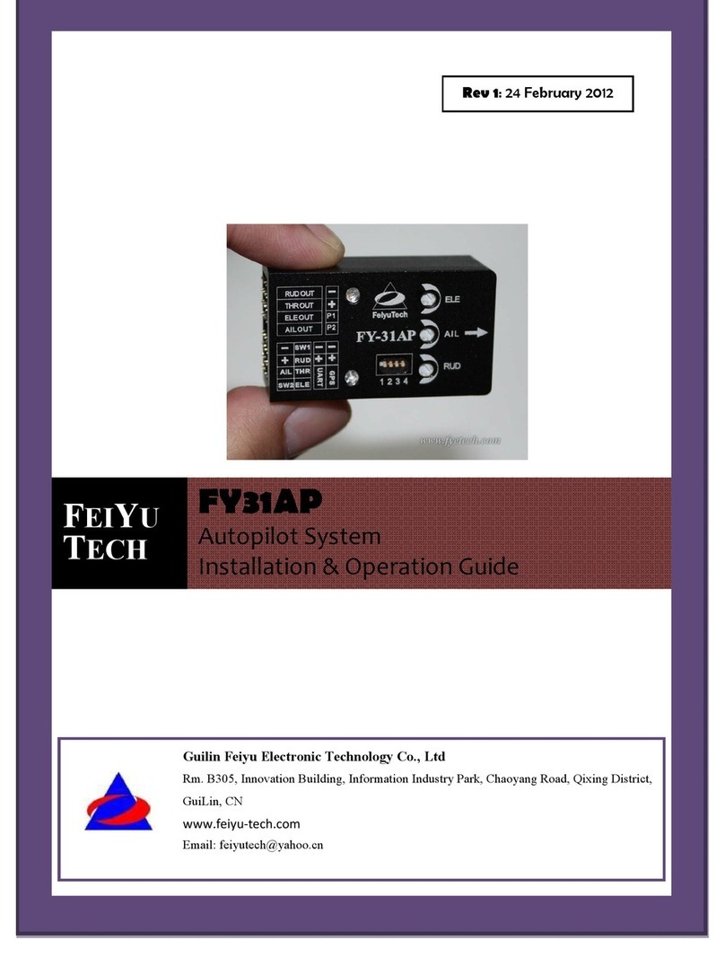
FeiYu Tech FY31AP Original operating instructions

2011-11-26
FEIYU
TECH
FY31AP
AutopilotSystem
Installation &Operation Guide
GuilinFeiyuElectronicTechnologyCo., Ltd
Rm.C407,InnovationBuilding, InformationIndustryPark, Chaoyang
Road, Qixing District,GuiLin, CN
www.feiyu-tech.com
Email: service@feiyu-tech.com

GuilinFeiyuElectronicTechnologyCo., Ltd
GuilinFeiyuElectronicTechnologyCo., Ltdhttp://www.feiyudz.cnE-mail: service@feiyu-tech.com
1
Dear Customer:
Thank you for choosing FY31AP as your autopilotsystem.Pleasereadthismanualcarefullybefore
using the systemto ensure proper use and operation.
The installation and useofthisdevice requiresomeskilland knowledgeinflying remote
controlled fixed wing aircraft.
·Ifyou areacompletebeginnerand have never flownone before,wedo not
recommend you installthisdevice on your own.
·Pleasefind assistance fromanexperience RCPilotwho may provide you withthe
basic knowledge required to use thisdevice successfully.
·Ifyou arealreadyanexperienced flyer,you willfind the FY31AP installation tobe
easy and logical. Just followthismanualand youwon tgo wrong.
Ifyou need anytechnicalsupportyou can send mail directlyto: service@feiyu-tech.com

GuilinFeiyuElectronicTechnologyCo., Ltd
GuilinFeiyuElectronicTechnologyCo., Ltdhttp://www.feiyudz.cnE-mail: service@feiyu-tech.com
2
1.AttitudeFlight StabilizationSystem (AFSS)
FY31AP isan inertialattitude measurementinstrumentused for automated stabilization offixed
wing modelaircrafts and simple three axiscameragimbals.
FY31APhas anintegrated three-axisgyroand three-axisaccelerometer which controlsthe aircraft
movementin three-dimensionalspace.
2.BarometricSensingandGPS
FY-31APcontrolmoduleincorporatesanaccuratebarometricpressuresensor.Atstartup,the
take-off air pressure ismeasured,providing the autopilotwith an accurate relative heightdata.
Whilethe GPSmoduleenablestheautopilottocalculatetheflightcourseand exactlocationof
the aircraft.Ifthe FY31AP isnotconnected GPSmodule,the autonomousflightsystemcannotbe
engaged and itwill function purelyas aflightstabilizer.
After connecting the GPSand booting up,the FY-31AP willsearch forGPSpositioning signals,the
first timetheGPSpositioning successfullyand the satellitesquantity at least 4,thenthe FY-31AP
willremember thisposition as the home point
3.FunctionOf FY-31AP
Byusing your remote control,the FY-31AP can be turned on oroff for the followingfunctions:
vLevelflight –When stabilization isactivated,the FY31AP willautomaticallycontrolthe
aircraftfor smootheasy flying.For beginnersin RCaircraftflying,thisisadvantagesas it
makesflighteasier andincreasesthestudentpilotself-confidence.The systemcanbe
activated throughoutthe entire flightduration,fromtake off to landing.
vEmergencyRecovery -Ifyou loseorientation releaseall controlsticks,maintainthrottle
and switch ONthe FY31AP.The unitwillautomaticallysend thecorrectsignalstobalance
ofthe aircraftand regainlevelflight,giving youtimetogetyourorientation and flythe
plane back to safety.
vAutonomousflight –withthe GPSmodulethe autonomousflightsystemofthe FY31AP
willenableyou toflyfullyautonomous,withup to8waypoints settingson the FYGround
ControlStation software.
vGroundControl Station –the FYGCS software willenableyou toflyautonomouslytoup
to8waypoints,display in-flighttelemetrydata,and recordthat flightfor replay and
analysis(thisrequiresthe optionalData Radio hardware).
vAutomatedcircling -byactivating thisfunction,the aircraftwill automaticallycirclethe
selected areaat afixed altitude,the centreofthecircleisthe currentpoint.You canset
the circling radius,the defaultradiusis80 meters.
vReturntoHome –You cansetautonomousreturn tohomeviaa3way switch or through

GuilinFeiyuElectronicTechnologyCo., Ltd
GuilinFeiyuElectronicTechnologyCo., Ltdhttp://www.feiyudz.cnE-mail: service@feiyu-tech.com
3
your failsafesetting,enabling you plane returningtohomeshoulditloseyourtransmitter
signal. Upon reaching thehomepointitwillautomaticallyengageautocircling,whileit
waits for your further instructions.
vFirstPersonView -for long-distance RCflightviavideo transmitter,the FY31APwill
maintainthe balance ofyour aircraft.You onlyneed tocontrolthe heading ofyour aircraft
and enjoythe view.
vFirmware upgrade –The FY31AP firmwareisupgradablebyconnecting toyour
computer viaaUSBTTLcable.AsFeiyuTech continuouslyimprovesthe FY31AP system,
firmware upgradeswillbe released periodically.
4.Optional Upgradewith FY-OSD andDataRadio
The FY-31AP providesanoptionalupgrade combining withthe FY-OSDand the Data Radio.With
thisadd-on,you willreceive:
lFirstPersonView(FPV):byconnecting thisinterface to the FY-OSD, telemetric data such as
GPS,flightnavigation,AHI canbe displayed on your downlink video.On the otherhand,it
willbe easier to operate FPVwith the functionsofautomatic balance and automated return
to home.
lRealtimetelemetry –realtimeby-directionaltelemetryismonitored directlybyyour
ground station computer.Changestoaircraft altitude and flightpathcanbecontrolled from
your ground station computer.
lRecordandmonitoryour flight - you can monitor and download your flightpath into your
ground station computer.
For more information,please refer to the FY-OSDand FYData Radio manual.
5.FY-31AP PackageContent
•FY-31AP controlmodule *1;
•GPSreceiver * 1;
•RCreceiver connectingwires* 1;
•Velcro double sided tape * 2;
•Some related wire.
•Instruction manual* 1;
6.Technical Specificationandworkingrequirement
lFY-31AP module:
Inputvoltage :4.0~6.0 Volt;
Currentdraw:50mA (5V);
Size:47x27 x20 mm;
Weight(excluding wires):25g;
Temperature range :-25 °C~+70 °C;
Maximumrate ofrotation : ≤2000 °/s

GuilinFeiyuElectronicTechnologyCo., Ltd
GuilinFeiyuElectronicTechnologyCo., Ltdhttp://www.feiyudz.cnE-mail: service@feiyu-tech.com
4
lGPSmodule:
Inputvoltage :3.0~3.3Volt;
Currentdraw:60mA(3.3V);
Size:32x32x10 mm;
Weight(excluding wires):22g;
Temperature range :-25 °C~+70 °C;
7.Application
The FY-31AP can be installed in the following aircraft :
1. Normal/Traditionalfixed-wing planes;
2.Delta-winged plane with rudder;
3.Delta-winged plane withoutrudder;
4.Planewithoutaileron;
5.V-tailplane with aileron;
6.V-tailplane withoutaileron;
7.Anyotherconfiguration ,please e-mail usforenquiry: service@feiyu-tech.com
8.Remotecontrol systemrequirement
The FY-31AP has been tested to work with the following RCsystems:
·Robbe-FutabaPPM /PCM 1024 /PCM G3mode,2.4GHzsystems;
·Graupner/JRPPM 8, PPM 12, SPCM mode;
·MPXPPM8,PPM 12 with UNI mode
·Anyremote controlsystemusing the standard of1.5 ms neutralposition.
9.FY-31AP Flight Modes
The FY-31AP has three flightmodes,you can activate anyofthe flightmodesviaafree Receiver
channeland a3-position switch (named as “SW1”)on your computer radio.
lMode1: DeactivatedMode.In thismode,all controlofthe aircraftisbythe pilot.The
FY-31AP doesnotparticipate in flightcontrol.
lMode2: Stabilizedmode
.
In thismode and your transmitter controlsticksat center,the
FY31APwillcontinuouslysend outcontrolling signal(aileron,elevator,rudder)toensurethe
aircraftmaintainsastabilized,horizontalflightand constantflightdirection.Inthismode
FY-31AP will notallowacrobatic flights.
lModel 3:Path Navigationmode,In thismode,the waypointwill be setaccording to the
flightpath to automatic flight.

GuilinFeiyuElectronicTechnologyCo., Ltd
GuilinFeiyuElectronicTechnologyCo., Ltdhttp://www.feiyudz.cnE-mail: service@feiyu-tech.com
5
10.FY-31AP AutonomousFlight Modes
Three autopilotmodesare incorporated into the FY-31AP,you can setitviaafree receiver
channeland a3-position switch (named as “SW2”).
lAutopilotmode1:
Deactivated.The autopilotfunction isnotactivated ,the flightmodesare
determinedbythe “SW1”.
lAutopilotmode2: AutoReturn ToLaunch RTL).When activated inthismode,the FY-31AP
willautomaticallyflythe plane back to the take-off point,while maintaining altitude.Upon
reaching the launch area,the unitwillautomaticallyflythe plane inacircleat adefaultcircling
radiusof80 meters.
lAutopilotmode3: Auto CirclingMode(ACM). When activated in thismode,the plane will
immediatelyflyin acircle.
The centre ofthe circle isthe pointofactivation
.The defaultcircle
radiusis80 meters.The aircraftaltitude will be automaticallymaintained throughoutthe
ACM.
Autopilotstall warning
a. The FY-31APhas somecontrol overthe throttlechannel. Therefore,when flying in
AutopilotModes,please ensure you have enough forward movementto preventstalling.
b. FY-31APmay have acontrolover the throttlechannel, butthe throttlecontrolsignalis
baseon the stick controlsignaland will autoadjust according the altitude and speed then
outputthe combined signal. Ifyourforwardmovementcannotcompensatefor the
autopilot sactive altitude hold,your aircraftwillstall.
c. ThisisespeciallyimportantifRTLispartofyour RCfailsafe.In the eventofRCLink lost,
you cansetRTLintoyourReceiverfailsafe.However,please DO NOT forgettoalsosetyour
throttle failsafe to between 25 % to50% to ensure the plane doesnotstall.
d. Never setyour throttle failsafe to zero.Ifyou do so,your aircraftwill RTLin acontinuous
stalled flightwhich will resultin acrash.
Attention: FY-31AP canwork in automatic flightmode,though withoutOSDmodule.Whether
you have been connected the OSDor not,FY-31AP can work normally.Butifthe FY-31AP isnot
connected GPSmodule,itwill function as purelyas aflightstabilizer.The autonomousflight
modescannotbe engaged.
11.RedLED Flashing& GyroscopeRe-set:
Ifthe following conditionsoccur,the FY-31AP initialization isrecommended:
(1) The device has notbeenused for alongtime.
(2) There isachange in environmentaltemperature ofover 30 degreessince last flight.
(3) TheRed LEDflashescontinuouslyeven whenthe FY-31AP remainsstationaryabout20s,and
you never activate the motor.
(4) Ifthe Red LEDison solidallthe timeevenwhen the FY-31AP isstationary,itmeansthe
gyroscope isfaulty,and the unitneed to be sentback for repair.

GuilinFeiyuElectronicTechnologyCo., Ltd
GuilinFeiyuElectronicTechnologyCo., Ltdhttp://www.feiyudz.cnE-mail: service@feiyu-tech.com
6
12.GyroscopeRe-setprocedures:
(1) Carryoutthisre-setting procedureonlyiftheabove occur.We do notrecommend regular
re-setting.Itisnotnecessaryand notrecommended.
(2) The stabilizer unitdoesnotneed to be in ahorizontalposition during initialization.However,
you must ensure thereisno vibrationduring thisprocess.Ifyoususpectshakingoccurred,
just restartthe initialization /resetting process.
Initialization/ ResetProcess
(1) Install the jumper as shownin thispicture:
(2) Power-ONthe FY-31AP and keep itstationaryforat least
20 seconds.You will noticethe red lightblinkwithtwo
differentrates.
(3) After 20 seconds,the re-setting /initialization is
complete.
(4) Disconnectthe power,unplug the jumper &remove it(keep safe for future use).
13.Flight modeIndicator(RedorBlue light)
Byobserving the flightindicator,you caneasilyre-confirmyour FlightMode switch settingsof
your radio.
Blue light:
Flight mode Stabilized
Mode
Deactivated
Mode
Path
Navigation
Mode
Return To
Launch (RTL)
AutoCircling
(ACM)
Blue LED light
indicator Stay on solid
continuous
flash Single flash
Double flash
each loop
Continuous
flashing.3times
each loop
FY
-
31AP

GuilinFeiyuElectronicTechnologyCo., Ltd
GuilinFeiyuElectronicTechnologyCo., Ltdhttp://www.feiyudz.cnE-mail: service@feiyu-tech.com
7
14.GPSstatus& vibrationlevel indicator
You can check the GPSlock statusand vibration levelbyobservingthe RedLED.
Redlight:
Status Toomuch
vibration
No GPSor GPS
stillnot lock
Needtoinitialize
Gyroorare moving
GPSlocation fixed
(4 satellites)
RedLED light
indicator Stay on solid
Stay off solidContinuous flashing
Continuous double
flash each loop
15.GPSReceiver
a. IfGPScannotfixthe aircraftlocation (minimum4satellites), only Mode1 (Deactivated) and
Mode2 (StabilizedMode) willfunction.Mode 3and Autopilotwill notbe functional.
b. Install the GPSModulewiththe antennaface up(see following picture).DONOTinstallnext
to metalor carbonfiber and other shielding material,which may block satellite signal.
c. Install the GPSModuleaway fromelectromagneticsourcessuch as ESC s,power wires,servo
wiresand videotransmitters.
GPS –SatelliteSignal LostDuringAutonomousFlight
lGPSprovidesthe aircraft geographic positioning,altitude,speed and flightdirection.
lOnlyifthe GPSData isavailable will the FY31APperformits AutopilotModes.
lIn case GPSsignalislost during flight,the autopilotwill keep its heightand course (not
lock)inautomatic navigation mode ,butits course may graduallydrift. After GPSsignalis
regained the planewill resume the AutopilotMode.
Green--Signal
Red---+3.3V
Black
-
-
GND

GuilinFeiyuElectronicTechnologyCo., Ltd
GuilinFeiyuElectronicTechnologyCo., Ltdhttp://www.feiyudz.cnE-mail: service@feiyu-tech.com
8
16.FY-31AP INTERFACE
lPininterfaceto sortthelist
8
7
6
5
4
3
2
1
NO.
GNDPowerP1P2GND3.3V TX0RX0 Ⅰ
RUD THRELEAILGNDPowerTX1RX1 Ⅱ
PowerPowerPowerPower
Switch 1
RudderThrottleElevator Ⅲ
GNDGNDGNDGNDGNDPowerAileronSwitch 2
Ⅳ
NOTE:Thepin”I-1,2,3,4”isfortheGPSmodule, “I-3”pinoutput+3.3V,sopleasedon’t
supplyto thispin, orwill burn theFY-31AP.
2
3
4
5
6
7
8
1
Ⅲ
Ⅳ
Ⅱ
POINTARROWFORWARD
(TOWARDS FLIGHT
DIRECTION)
Function DIP
Aileron
sensitivity
knob
J
umperinstalled
during gyro
initialization.
Do not insertjumper
during normal use.
RedLED: theGPS
status&vibration
levelindicator
Rudder
sensitivityknob
Elevator
sensitivity
knob
BlueLED: Flight
modeindicator.
Interfacepin panel

GuilinFeiyuElectronicTechnologyCo., Ltd
GuilinFeiyuElectronicTechnologyCo., Ltdhttp://www.feiyudz.cnE-mail: service@feiyu-tech.com
9
lDIP SwitchFunction:
Switch
number
1234
ON For Factory
use only
FlightMode
Selection
FlightMode
Selection
Adjust flight
patterns
OFF Always OFF
position
FlightMode
Selection
FlightMode
Selection
Normal
mode
Note:
1. In thismanual,the direction for allthe DIP switchesisshown bywhite color .
2.the position forthe DIP switch 1is OFF,ifitwas putinON,then the FY-31AP cannotwork
normally.
lGPSfeatures
The FY31AP GPSpin interface consist of:GND,3.3V voltage,TX0,RX0.The characteristicsare:
·Data bits:38400
·Interface Features:TTLlevel
·Data bits:8
·Stop Bits:1
·Parity:None
Connectthe above tothe GPSReceiver.The GPSdata protocolisastandardNEMA0183 and the
statementmust be $GPRMC,$GPGGA.
NOTE:The pin”I-1,2,3,4”isfor the GPSmodule, “I-3”pinoutput+3.3V,sopleasedon t
supplyto thispin,or willburn the FY-31AP.
lUARTInterface
The UARTpin interfacesconsist of:GND,power,TX1, RX1.The characteristicsare as follow:
·Baud Rate:19200
·Data bits:8
·Stop Bits:1
·Parity:None
·Interface features:TTL
The pininterfacesoutputtelemetrydata.Thisinterface connects tothe data radio,PCcomputer
serialportorOSDmodule.You cansettheflightroute,navigation and controlparametersof
FY31AP bythisinterface.The portisalsoused toupgrade FY31AP firmware.
Please read the procedure for the firmware upgrading.
lFY-31AP Electrical ConnectionandDiagram
a) Power supply
lThe FY-31AP operatesbetween 4to6volts input.
lFY-31AP ispowered viathe Receiver connection.
lIfyour plane isElectric powered,the Receiver power supplyisnormallyfromthe ESC built-in
BatteryElimination Circuit(BEC).However,we highlyrecommend that aseparate BECwith a
3A output.

GuilinFeiyuElectronicTechnologyCo., Ltd
GuilinFeiyuElectronicTechnologyCo., Ltdhttp://www.feiyudz.cnE-mail: service@feiyu-tech.com
10
lFor Gas or Nitro powered planes,you willrequire abatteryto power the Receiver and
FY-31AP.
b) ConnectionsThe FY31AP isconnected toyour RC
Receiver viaa6wirecable.You need aminimum6
ChannelRCReceiver.
lFY-31AP requiresaminimumof6-channelRCreceiver.
l4Receiverchannelsareused foraileron(channel1), elevator (channel2) ,throttle(channel3)
and rudder(channel4) signaloutput. Connectthese4receiver outputsignalsto the FY-31AP with
the supplied wires(pay attention to the color ofeach channel).
l2free Receiver channelsare required to controlthe FY-31AP FlightModes(3-position switch
or dialknob, ”SW1”)and AutopilotMode (3-position switch or dialknob, ”SW2”).
c) Note that the wireisarranged accordingto color :
Wire colorReceivechannel
White
(bundledwith red& black)
aileronChannel1
orange elevatorChannel2
green throttleChannel3
yellow rudderChannel4
brown
SW 1
Anyfree channelcontrolled by
3-way switch or dialknob
Channel5
blue
SW2
Anyfree channelcontrolled by
3-way switch or dialknob
Channel6
17.Vibrationdamping
A. FY-31APisvibration-sensitive.Tooptimizeits stabilization capability,vibrationsreaching the
1
2
3

GuilinFeiyuElectronicTechnologyCo., Ltd
GuilinFeiyuElectronicTechnologyCo., Ltdhttp://www.feiyudz.cnE-mail: service@feiyu-tech.com
11
unitmust be keptat aminimum.
B. When installing thisflightstabilizer,wehighlyrecommend that you install itwiththe supplied
vibration absorbing pads(dampers).
C. The algorithminthe FY-31AP compensatesfor normallevelsofflightvibration.However,if
the vibration experienced bythe unitexceedstheacceptablelevel, itwillnotwork normallyor
may even stop working altogether.
D. Tokeepvibrationat aminimum,installthe FY-31APaway fromthe engine or anyother
vibration sources.
E. The includedshock-absorbing padswill meetthe damping
requirements for electricpowered aircrafts and most gas/nitro
planes.
F. The FY-31AP issupplied withthe double-sided foam padding
dampers.Please use themas shown:
lCheckingforVibrationLevels
Even withthe shock absorbing mount, your aircraftinstallation may notmeetthe damping
requirements ofthe FSS.To confirmcorrectvibration damping,please followthisprocedure:
A. After connecting all wiresbetweenthe FY-31AP,Receiver and ESC,install the unitas
recommended (ensurecorrectorientation).
B. Run the plane engine ormotor at differentthrottle levels. DO NOTTAKE OFF.
C. Move the throttle levelto differentpositionsandmaintain itfor 20secondsat each position.
D. Ateach throttleposition,observe the stateofthe red LEDlight.Ifitstays OFF,that meansyour
vibration levelisacceptable.
E. Ifinsteadthe red LEDlights up brightand stays ONsolid,then the vibration dampening isnot
enough.You will need reduce the levelofvibrationon your aircraft,add additionaldampening
supportor change the installation location.
18.SW 1 andSW 2 :SwitchSettingsforFY31AP
a. SW-1 Flight Modes
The FY31APhas 3Flightmodescontrolled viaSW-1.Toselect
the modes,useafreeReceiverchannelcontrolledviaa3
way-switch:
FY-31AP flight modes
SW-1signaloutput900-1200us1200-1800us1800-2100us
FunctionalmodeDeactivatedMode
Auto Stabilize
Mode PathNavigationMode
BlueLEDlight
indicator continuousflashStayonsolidSingle flash

GuilinFeiyuElectronicTechnologyCo., Ltd
GuilinFeiyuElectronicTechnologyCo., Ltdhttp://www.feiyudz.cnE-mail: service@feiyu-tech.com
12
b. SW-2 AutopilotModes
FY31AP AutopilotModesiscontrolledviaSW-2.
IMPORTANT: The AutopilotMode (SW-2) hascontrolling priority overthe FlightModes
(SW-1).Ifyou wish to use the FlightMode (SW-1), you must de-activate the Autopilotfirst.
SW-2signaloutput900-1200us1200-1800us1800-2100us
Functionalmode ReturnToLaunchMode
(RTL) Cancel Mode Auto Circling Mode
(ACM)
BlueLEDlight
indicator
ContinuousDoubleflash
eachloop / Continuousflashing.
3 timeseachloop
00-1200us ReturnToLaunch Mode
1200-1800usCancelMode
1800-2100us AutoCirclingMode
900-1200us DeactivatedMode
1200-1800us AutoStabilizationMode
1800-2100us PathNavigationMode

GuilinFeiyuElectronicTechnologyCo., Ltd
GuilinFeiyuElectronicTechnologyCo., Ltdhttp://www.feiyudz.cnE-mail: service@feiyu-tech.com
13
19.Planeconnectinglayout
1) FY-31AP connection for traditionalaircraftlayout:
AILOUTELE OUTTHROUTRUDOUT
Aileron
Servo
Elevator
Servo
Throttle
Servo
Rudder
Servo
2) FY-31AP connection for flying wing aircraft:
(with or withoutRudder)
AILOUTELE OUTTHROUTRUDOUT
Differential
Servo 1
Differential
Servo 2
Throttle
Servo
Rudder
Servo
3) FY-31AP connection for Vtailaircraftwith Aileron:
AILOUTELE OUTTHROUTRUDOUT
Aileron
Servo
Differential
Servo 1
Throttle
Servo
Differential
Servo 2
4) FY-31AP connection for Vtailaircraftwithoutailerons:
AILOUTELE OUTTHROUTRUDOUT
Differential
Servo 1
Differential
Servo 2
Throttle
servo Null
5) FY-31AP connection for traditionallayoutaircraftwith no Aileron:
AILOUTELE OUTTHROUTRUDOUT
Rudder
Servo
Elevator
Servo
Throttle
servo Null
6) CameraGimbalStabilization:
AILOUTELE OUTTHROUTRUDOUT
RollServo
TiltServoNullPan Servo
*Note: The cameragimbalRoll,Tiltand Panservoswill counteranylinearmovementofthe
cameramount.You can move the cameraat anyangle and upon releasing the stick,the FY-31AP
willmaintainstabilization at that angle.The FY-31AP isonlysuitablefor the cameragimbal
controlwhich the controlaccuracy is not very high.

GuilinFeiyuElectronicTechnologyCo., Ltd
GuilinFeiyuElectronicTechnologyCo., Ltdhttp://www.feiyudz.cnE-mail: service@feiyu-tech.com
14
20.Connectionof FY-31AP
21.FY-31AP installation: Orientation,Positionandlevel
a) The FY-31AP has anarrowprinted on the top ofit.Orientatethe arrowtowardsthe frontofthe
craft(i.e.direction offlight).
b) When installing,please keep the FY-31AP horizontaland as close as possible to the "Centre of
gravity" (COG) ofthe aircraft.(as the following diagram)
c) The controlbenchmark ofFY-31AP isthe NEUTRALVALUE position.Butwhen install the dip
angle between FY-31AP and the plane still should be notmore than 15 deg.
Brown
Yellow
Green
Red
Black, red, white
Blue
AILOUT
RUD OUT
ELE OUT
Battery
Electric
Motor
THR OUT
ESC
OSDModule
DataRadio
GPS
Module
RC receiver

GuilinFeiyuElectronicTechnologyCo., Ltd
GuilinFeiyuElectronicTechnologyCo., Ltdhttp://www.feiyudz.cnE-mail: service@feiyu-tech.com
15
d) Ifthereisdeviation between the neutralvalue position and the plane slevelflight,itmay
causedeviation offixing plane slevelflight.See next topic.Butthesedeviation can be amend
byrecording the neutralvalue.Pleaserefer “RECORDINGYOURAIRCRAFT NEUTRALVALUE.”
22.AdjustmentDialsforELE,AIL andRUD
1. There are 3adjustmentdialson the FY31AP.Each dialcontrols both gyro gain
and
servo
direction during auto stabilization.
Planenosewill pitch
downwhen inAuto
StabilizationMode.
Planenosepitchesupwhen
inAutoStabilizationMode.
Planepitch remains
levelwheninAuto
StabilizationMode
FY
-
3
1
A
P
Planewill rollto
theleft when in
Stabilized Mode
FY-31AP
Plane rollremains level when inAutoStabilization Mode
FY-31AP
FY-31APwillrollto
therightwhenin
Stabilized Mode
The3dialscontrolboth gain &servodirection.
+100 Max
-
100 Max
0 Min

GuilinFeiyuElectronicTechnologyCo., Ltd
GuilinFeiyuElectronicTechnologyCo., Ltdhttp://www.feiyudz.cnE-mail: service@feiyu-tech.com
16
2. GyroGain: Thefurtheraway fromCentre (12O clock)the higherthe Gyro gain
(sensitivity).Toolowgainresultispoor autostabilization,toohighgainwillcause
oscillationsofthe aircraft.You needto adjust thegain setting based on the requirement
ofyour aircraft.
3. ServoDirection: The dialsalso controlthe direction ofyour servo movement.Turning it
clockwiseor counterclockwisefrom12O clock willchange the direction ofyour servos
during stabilized flightagainst tilting,roll and yaw.
23.CONTROL SURFACE MOVEMENTCHECK
Install FY31AP as recommended inthismanual, then proceed toconfirmcorrectcontrolsurface
movementdirection in Mode 2or Mode 3.
1. In Manualmode (stabilization deactivated)confirmthatthe controlsurfacesdo toreactwhen
your aircraftistilted or rolled.
2. ActivateMode 2(Autostabilizemode)andobserve the movementdirection ofAileron,
Elevator and Rudder.The direction shouldbe as shownbelow.Ifdirection iswrong,turn the
appropriate dialto the opposite side of12O clock to getthe action direction correct:
AILERONS -Roll the plane to see the following action:
lIncline the plane tothe right(roll right).The aileronsshouldgive acontrolsignaltocounter
thisroll direction (see below). Sameas when rolledtothe left.Ifthe aileronsmove correctly,the
knob has been turned inthe rightdirection.Youcannowadjust gainbymoving nearer (low
gain)or further away (high gain)fromcenter;
lIfthe aileronsdo notfollowthe movements shown above,simplyturn the aileron knob to the
opposite side (beyond centre). You should nowsee the correctaileron movement.
Leftaileronautomatically
moveupward.
Roll right
Rightaileronautomatically
movedownwards.
Rightaileronautomatically
moveupwards
Roll left
Leftaileronautomatically
movedownwards
AileronMovementInAuto StabilizationMode
MaxGyro Gain MaxGyro Gain
12 O clock
Min Gyro Gain
Servodirectionchange
in Mode3&2.
Servodirectionchange
in Mode3&2.

GuilinFeiyuElectronicTechnologyCo., Ltd
GuilinFeiyuElectronicTechnologyCo., Ltdhttp://www.feiyudz.cnE-mail: service@feiyu-tech.com
17
Elevatormovesdown
Elevatormovesup
Nose Up
Nose Down
ElevatorMovement InAutoStabilizationMode
ELEVATOR - Pitch the plane nose up and downto see the following elevator action:
lInclinethe planeNOSEUP.Youshouldseethe elevator move down.And when you move the
NOSE DOWN, the elevator should move up.
lMove the Elevator knob to the opposite side (fromCentre)ifthe servo movementisincorrect.
RUDDER - Turn your planeclockwise or counterclockwise to see the rudder movementbelow:
lMove the Rudder knob to the opposite side (fromCentre)ifthe servo movementisincorrect.
lAdjust Rudder gainaccordingtoyouraircraftrequirement(lowest gainnearest tocentre,
highest gain further away fromcentre).
24.RECORDINGYOURAIRCRAFTNEUTRAL VALUE
1. The FY31AP canrecord your aircraftbest stabilization attitude in its memory.Byrecording
this ‘NeutralValue ,the FY31APcanknowhowbest tocontrolyouraircraftfor
optimumstability.
2. You can do thisprocedure with the aircrafton the ground or inthe air.
3. Setting the NeutralValueon the ground isquick and easy and will produce good
stabilization results.However recording neutralvalue ‘on the fly will resultinmore
accurate autonomousflightattitude control.
Rotateright Rotateleft
Rudder moves
totheleft
Rudder moves
totheright
RudderMovement Auto StabilizationMode

GuilinFeiyuElectronicTechnologyCo., Ltd
GuilinFeiyuElectronicTechnologyCo., Ltdhttp://www.feiyudz.cnE-mail: service@feiyu-tech.com
18
lRecordingNeutral Value ontheGround
Step1: Setup your aircraftand ensurecorrectFY31AP orientation,
position &leveling.Ensurethe Mode 3(autostabilization)Elevator,
Aileron and Rudder movements are in the correctdirection.
Step2: Move Dip Switch No.4to ‘ON position.
Step3: Place youraircrafton atable.Arrange the aircraftsothat isperfectlylevel. Position the
aircraftexactlyas youwishittobeduring autostabilization flight(i.e.fuselage andwings
perfectlylevel).
Step4: ONyour transmitter and zeroall your trims.Powerup the FY31AP in Mode1(Manual
Mode).Confirmthere areno deflectiontotheAileron,Elevatorand Rudder surfacesby
adjusting your servo links.Re-confirmthat youraircraftisperfectlylevel. Thisisyouraircraft
Neutralposition.
Step5: While in Step 4leveled position,activateMode 3(Auto Stabilization Mode)for atleast
2 seconds.Since Dip Switch No.4isON, the FY31AP will nowrecord the NeutralPoint.
Step6: After2seconds,move DipSwitch No.4back to OFF position.
The procedure iscomplete and the systemisreadyfor flight.
Note: when the DIP SwithNO.4isinthe ONposition,the FY-31AP will
recordthe neutralpointfor each timeyou switch the mode from Mode1:
DeactivatedMode to Mode2:Stabilizedmode.
25.Checkingthecontrol surface& LED beforefly
lBeforeyour flypleasereconfirmcorrectcontrolsurface movementdirection bothinRCcontrol
mode(Mode1) and Stabilized mode(Mode2).
lSwitch the SW1and SW2, to observe ifthe blue LEDflash in the correctway in each mode.
lObserve the Red LEDtoconfirmifthe GPShave locked,ifyes,then you cantakeoffyour plane.
26.Stabilizedmode(Mode2)TestAndSensitivity Adjustment
lAtthisstage,your aircraftshouldalreadyhave automated surface controlwiththe right
direction when in Auto Stabilized Mode and the NeutralValue isalreadyrecorded.
lNowyou need tofinetune your FY31APstabilitygainviaflighttests.For the first flightitis
recommended that thegainsnotbe settoohigh.Toavoidexcessiveoscillation(flight
overcorrection)putthe gyro gain at mid point.
lTakeoff inMode 1(ManualMode). After achieving safeheight,activateMode 3(Auto
Stabilized).
lAileronGain: Ifyou seeoscillation ofthe wings,thisindicatesthe Aileron gainissettoo high.
Switch back to Mode 1and land the airplane.
lReduce the sensitivity (move dialtowardscentreposition)and flyagain.You shouldsee

GuilinFeiyuElectronicTechnologyCo., Ltd
GuilinFeiyuElectronicTechnologyCo., Ltdhttp://www.feiyudz.cnE-mail: service@feiyu-tech.com
19
improvementinwing attitude.Adjust until you aresatisfied withthe levelofwing
stabilization.
lElevator&Rudder Gain: Too much Elevator gainwill showthe tail moving up and down
(nodding).Toomuch Rudder gainwillshowtailwagging.Reducegainuntilthisflightover
correctionsdisappears.
lAlternately,ifyou find the flightcorrectionisnotenough (too lowstability), youcan increase
gain accordingly.
27.RecordingNeutral Value ‘OntheFly’
After the checking for the controlsurface,adjust the 3knob switch toasuitableposition(advice to
adjust for abouthalf),then you cantestthe flynow.The test for flyisinorder torecordthe neutral
value ‘on the fly .Thiscan help you getmoreaccurate autonomousflightattitude control.
Itisbest to carryoutthisprocedure during minimalwind conditions.
Step1: Setupyouraircraftand ensurecorrectFY31AP
orientation,position&level.Ensurethe Mode 3(auto
stabilization)Elevator,Aileron and Rudder movements areinthe
correctdirection.
Step2: Move Dip Switch No.4to ‘ON position.
Step3: ONyour transmitterand zero allyourtrims.Confirm thereare no deflection to the Aileron,
Elevator and Rudder surfacesbyadjusting yourservo links.
Step4: Power ONthe aircraftwith the FY31AP inManual Mode.
Step5: Flyyouraircraftto asafe height(stillinManualmode)and flyin aLeveland straightline.
Step6: WhileinthisNeutralValue,activateMode 2(AutoStabilization Mode)forat least 2
seconds.Since DipSwitch No.4isON,the FY31AP will nowrecordyour NeutralValue.After2
seconds,switch back tomanualmode or keep inthe Mode 3(AutoStabilization Mode)and land
your aircraft.
(Note: Donotswitch fromMode 1(Deactivated Mode)toMode 2(Stabilized mode)for the second
time,becausewhen the DIPSwitch NO.4isinthe ONposition,the FY-31AP willrecordthe neutral
pointeach time you switch the mode fromMode 1to Mode 2.)
Step7: After landing,move DipSwitch No.4back to OFF position.
Procedure iscomplete.
IMPORTANTNOTE:Aslong as thereareno major changesinyouraircraft
hardware(e.g.no shifting ofCentreofgravity, ”CoG”)your NeutralValue will notchange.If
therearemajor changesinhardwareoryourCoGhave shifted,itisbest you repeat thisNeutral
Value recording procedure.
Note: ifyouhavedata radio,youalsocanusetheGCSsoftwaretorecordtheneutral
value ’onthefly’moreeasily!The detailplease referthemanualof GCSsoftwareoperate
manual.
Other manuals for FY31AP
1
Table of contents
Other FeiYu Tech Autopilot System manuals
