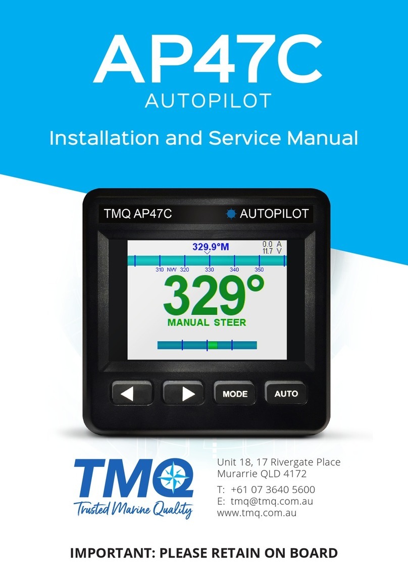
TMQ AP47CR User manual

AP47CR Quick Start Guide
IMPORTANT: THE AUTOPILOT SHOULD NOT BE LEFT SOLELY IN CHARGE OF THE VESSEL
AND AN ADEQUATE WATCH SHOULD BE MAINTAINED AT ALL TIMES. IT IS STRONGLY
RECOMMENDED THAT THE AUTOPILOT SHOULD NOT BE USED WHILE NAVIGATING IN
RESTRICTED WATERWAYS AS WATER CURRENTS, WIND CHANGES OR RADIO TRANSMITTER
INTERFERENCE CAN ENDANGER YOUR OWN OR OTHER VESSELS.
The set up can be done automatically or manually
Automatic installation set up determines the output
polarity for motor direction and rudder limit setting.
Note: If the manual set procedure is used, motor
direction and both rudder end limits must be set.
Rudder End Limits – Automatic Set up (Rudder
Feedback required)
To commence:
• Switch power on to AP47C
• Wait until Main Screen is displayed (Figure 1)
• Hold MODE button, Settings Page 1 will appear
(Figure 2) release MODE button.
• Press MODE and AUTO buttons at the same time.
Install Options 1 will appear (Figure 3)
• Press AUTO button to enter Steering Menu
(Settings Page 2) Figure 5
• Ensure USE RFU is set to YES
• Scroll down to END LIMIT AUTO using the ►Button
• Press AUTO button to start set up (Figure 4)
• Process will take between 20 and 60 seconds to
complete depending on the speed of the motor
• If process is successful display will show
CAL OK
SAVING….
• Press either MODE to cancel the installation process
• Display will show ABORT CALIBRATION
• If CAL ERROR is displayed an error has occurred
• Check the drive output is connected and rudder
feedback is moving
• Check rudder feedback installation
• To Exit menu, press MODE button
Rudder End Limits – Manual Set up
(Rudder Feedback required)
• Switch power on to AP47C
• Wait until Main Screen is displayed (Figure 1)
• Hold MODE button, Settings Page 1 will appear
(Figure 2). Release MODE button.
• Press MODE and AUTO buttons at the same time.
Install Options 1 will appear (Figure 3)
• Press AUTO button to enter Steering Menu
(Settings Page 2) Figure 5
• Ensure USE RFU is set to YES
• Scroll down to END LIMIT PORT using the
►
Button
• Press AUTO button to enter Port Adjustment
(Figure 5)
• Press
◄
to move rudder to Port
• Press
►
to move rudder to starboard
• If direction is incorrect, reverse the yellow wires,
or change SWAP OUTPUT in previous menu.
• Move to Port Limit, press AUTO button (Figure 6)
• Press AUTO again to save, or MODE to abort.
• Scroll down to END LIMIT STBD using the
►
Button
• P
ress AUTO button to enter Starboard Adjustment
• Move to Starboard Limit, press AUTO button
• Press AUTO again to save, or MODE to abort.
• To Exit menu, press MODE button
INITIAL OPERATIONAL SETTINGS (AP47CR) – WITH RUDDER FEEDBACK
Figure 1: Example Main Screen Figure 5: Port Limit Adjustment
Figure 3: Example Install Options 1
Figure 2: Example Settings Page 1 Figure 6: Save Limits
Conrmation Screen
Figure 4: Example Settings Page 2

AP47CR Quick Start Guide
To Adjust Settings:
• With Main Screen displayed (Figure 1)
• Hold MODE button, Settings Page 1 will
appear (Figure 2). Release MODE button.
• Press ►to scroll down to desired setting (Setting
will be highlighted green)
• Then press AUTO to enter setting adjustment
• Press ►to increase setting
• Press ◄to decrease setting
• Press MODE to return to Settings Page 1
Rudder Ratio (Proportional Gain) Default = 3
A value of 1 signies the minimum amount of applied
rudder. When the rudder setting is too low, vessel
track will be slow i.e.: understeer due to too little
rudder applied. A value of 20 signies the maximum
amount of applied rudder. When the rudder setting is
too high, vessel track will be rapid i.e.: oversteer due to
too much rudder applied.
Rudder Sensitivity (Rudder Tolerance) Default = 4
Increasing the Rudder Sensitivity too high can cause
vessel wandering
Error Gain (Integral Control Gain) Default = 5
Increase Error Gain to get on track faster. If set too
high, the vessel will overshoot the target heading.
Rate of Change (Derivative Gain Multiplier) Default = 3
Increasing Rate of Change can help dampen Error
Gain. If set too high, vessel may never make it to target
heading.
Rate of Turn (Default = 500°M)
This limits the max turn speed of the vessel. Reduce
this to reduce the angle of attack for getting to target
heading.
Dead Band (Default = 1.0°)
Increase this to reduce rudder hunting.
BOD Correction (Applies to GPS Mode only)
Default = 15
This number increases or decreases the angle of
attack from a GPS / PC supplied BOD (Bearing Origin to
Destination) when in GPS mode.
Reverse Delay (Default = 15)
This delay helps reduce shock load on the rudder drive
train, as it controls the time between direction changes
(eg. Port to Starboard or Starboard to Port changes)
Minimum Speed (Only used with no rudder
feedback) Default = 1.0kn
When the vessel is below this set speed and in Auto or
GPS mode, the AP47C will revert back to Manual mode.
Backlight Bright (Default = 15 = MAX)
This setting is useful for adjusting screen brightness for
day / night or low lit areas.
Wind Mode (Requires MWV NMEA data input)
Default = OFF
When Wind Mode is ON, the AP47C will attempt to
correct for wind eects on vessel steering.
Main Screen Explained
Manual Steer Mode
The live compass heading is displayed in the top
center, as a bar-graph below it, and in large green
numbers near the middle of the screen.
Below the large numbers is the current steering
mode (MANUAL STEER), or an error in red.
Rudder Angle is indicated by a bar and number.
Figure 7: Example Manual
Steer Mode Main Screen.
Live Compass heading is
185°, Rudder is at center.
Press ◄or ► buttons to
move the rudder.
Hold MODE to enter
Settings Page 1.
Press AUTO to enter Auto Steer Mode.
Hold MODE and press AUTO to enter GPS steer mode.
Auto Steer Mode:
The current target heading is in large yellow numbers
near the middle of the screen.
If a yellow bar appears within the compass bar, it
indicates current deviation from target heading.
Figure 8: Example Auto
Steer Mode Main Screen.
Live Compass heading is
315°,
Target Heading is 315°,
Deviation is shown as
a yellow bar within the
compass bar.
Press ◄or ►buttons to change the target heading.
Hold MODE to enter Settings Page 1.
Press AUTO to enter manual steer mode.
Briey press MODE to toggle target heading step size
between 1°and 10°(indicated in yellow brackets).
GPS Steer Mode:
GPS heading is presented in large blue numbers.
If a yellow bar appears within the compass bar, it
indicates current deviation from target heading.
Figure 9: Example GPS
Steer Mode Main Screen.
Live Compass heading is
314°, Target Heading is
313°, Deviation is shown
as a yellow bar within the
compass bar. DOD correction
is displayed in blue.
Hold MODE to enter Settings Page 1
Press AUTO to enter Manual Steer Mode.
Press ◄or ►to adjust BOD correction.
Other TMQ Autopilot System manuals
