Fell Marine MOB Plus xHUB User manual
MAN OVER BOARD
WIRELESS MOB DETECTION
AUTO ENGINE STOP
If this is the first time you use the MOB+, visit
www.fellmarine.com/explore
To see install videos, demos, FAQs, online user manual
and other support material, visit:
www.fellmarine.com/support
Thank you for choosing MOB+!
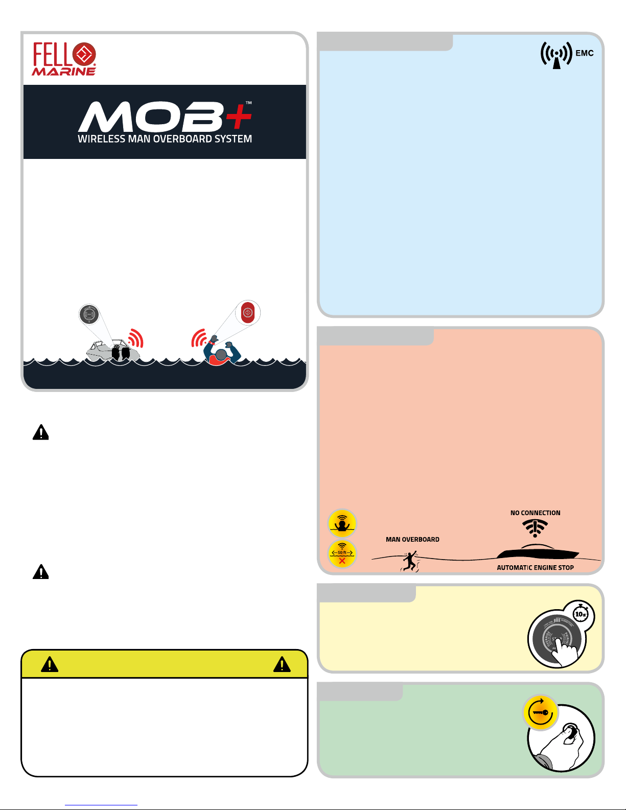
The xFOB is waterproof down to 10 ft./3m and can be reused after
MOB event. After an MOB-event, the engine can easily be restarted
by;
• dStart - 6 seconds after a MOB Event the system lets
passenger restart the engine to pick up the missing person in
the water. The engine can be started without reconnecting the
xFOB. No interaction with xHUB necessary.
• Reconnect with the xFOB by clicking once on the xFOB to
deactivate dStart and once more to connect.
IMPORTANT INFORMATION
FELL Technology AS
Designs, manuals and features subject
to change. For more information visit our
website: www.fellmarine.com
LEARN MORE AT: WWW.FELLMARINE.COM
Disconnect battery cables at battery before attempting to install
this product
Read all instructions carefully before use of this product.
FELL Marine equipment and accessories are designed to
the best industry standards for use in the recreational marine
environment. Their design and manufacture conforms to the
appropriate Electromagnetic Compatibility (EMC) regulations, but
correct installation is required to ensure that performance is not
compromised. Please see section EMC Installation Guidelines in the
User Manual for optimum EMC conditions.
Within the wireless range MOB+ will not shut down the engine
automatically e.g. if you fall in your boat within the wireless range the
engine will not stop automatically. In this event, you can shut down
the engine by pressing the button on your MOB+ xFOB or on the
MOB+ xHUB. Always check your wireless range before use.
WARNING
CAUTION
MOBP17001
MAN OVER BOARD
MOB Mode (Man Overboard Mode) is the safety mode of the
system. MOB+ will automatically activate shut down of the engine
when the STOP FOB is submersed in 4 inches (10 cm) of water or
travels out of range from the xHUB. After 6 seconds, the system
automatically activates Override Mode. In Override Mode any
passenger or crew on board can restart the engine without the need
to interact with the MOB+ system. This allows for a quick recovery of
the missing person in the water and enhances safety.
ALARM FUNCTION: If any of the ALARM FOBs falls overboard
the xHUB will NOT stop the engine(s), but sound the MOB Alarm,
ashing on the xFOB Connection Indicator on the xHUB and blink
red in the light circle. The alarm continues until the STOP button on
the xHUB is pushed to disengage the alarm.
MOB EVENT RECONNECT: In an MOB event where the STOP FOB
falls overboard, the person returning from the water can reconnect
the xFOB by one click to disable MOB Mode, followed by one more
click on the xFOB to reconnect. Alternatively, remaining passengers
with an ALARM FOB can choose to connect one of their xFOBs.
MOBP17003
In the event that you forget your xFOB or if
it´s out of battery - don´t worry. You can easily
override MOB+ by holding the button on the
xHUB for 10 seconds. The xHUB will give a
sound signal and a yellow light signal every 30
seconds to indicate Override Mode is activated
so you can start the engine(s).
OVERRIDE MODE MOBP17004
dStart™
dStart is the direct restart feature in the
MOB+ system. 6 seconds after an MOB event
with a STOP FOB, the MOB+ automatically
activates Override Mode to allow any remaining
passengers in the boat to restart the engine(s)
directly, without interacting with the system.
The Override Mode ashes yellow and gives a
sound feedback every 30 seconds.
MOBP17005
REV200-0318
EMC GUIDELINES
The guidelines given here describe the conditions
for optimum EMC performance, but it is recognized that it may
not be possible to meet all of these conditions in all situations. To
ensure the best possible conditions for EMC performance within the
constraints imposed by any location, always ensure the maximum
separation possible between dierent items of electrical equipment.
For optimum EMC performance, it is recommended that wherever
possible:
FELL equipment and the cables connected to it are:
• At least 3 ft. (1 m) from any equipment transmitting or cables
carrying radio signals e.g. VHF radios, cables and antennas.
In the case of SSB radios, the distance should be increased to
7 ft. (2 m).
• More than 7 ft. (2 m) from the path of a radar beam. A radar
beam can normally be assumed to spread 20 degrees above
and below the radiating element.
• If possible the product is supplied from a separate battery
from that used for engine start. Power supply voltages below
the minimum specied 7V power source, and starter motor
transients, can cause the product to reset. This will not damage
the product, but may cause inability to start the engine.
• FELL specied cables are used. Cutting and rejoining these
cables can compromise EMC performance and must be
avoided unless doing so is detailed in the installation manual.
MARCH 2018 © FELL Technology AS Page 1/9REV200-0318

11,5 mm
(0.45 inch)
44 mm
(1.7 inches)
28 mm
(1.1 inches)
Measurements and performance
Weight 164g / 5.8oz.
Housing material ASA / TPU / PBT / POM – RoHS
Temperature range From -15°C / 5°F to 55°C / 131°F
Voltage Source 10-32Vdc
Power consumption Active Mode: 180mA (2.5W max. at 13.8Vdc), Standby: <30mA,
<0.4W max. at 13.8V
Fuse 1A-3A
Alarm decibel level >85db
Kill Switch Relay Max Current Tolerance 5A continuously
Wireless performance
Frequency area EU: 868 MHz US: 915 MHz
RF signal (in) 10 dBm max.
RF signal (out) 10 dBm max.
4D Antenna diversity
Certifications and compliance
Radio - xHUB EU: R&TTE, EN 300 328,
Maritime/CE
US: FCC Part 15C
EMC - xHUB EU: EN 301 489-01
(V1.9.2), Class A
US: CISPR 16-1
Flammability - xFOB IEC 60950 1&22, CE-UL94
Immersion xFOB IEC 60945, IP68, Maritime/CE - 3m / 10ft. water resistant
RoHS (2002/95/EC) compliant materials
ABYC A-33 compliant
228 mm
(9 inches)
166 mm
(6.5 inches)
49 mm
1.9 inches)
66 mm
(2.6 inches)
62 mm
(2.45 inches)
52 mm
(2 inches)
17 mm
(0.7 inch)
External Antenna
Self-locking Nut
xFOB Connection Indicator
Pairing, Override
and Stop Button
Light and Sound Alarm
Internal Antenna
• How can I override the system if the system fails or if I
have lost the xFOB?
-If the system fails use the End Cap Connector attached to the
main xHUB cable to mechanically override the system.
-If you have lost your xFOB press and hold the button on the
xHUB for 10 seconds to put the system in Override Mode.
• I already have an existing kill switch. Can I install MOB+?
-Yes. MOB+ is installed using wires from your existing kill
switch. Please see installation guide for instructions
• I have a boat made from metal. Can I install MOB+?
-Actual signal reduction, if any, will vary from boat to boat.
Should the signal be noticeably worse, we recommend
using an external antenna to put on the top side of the helm,
supplied from FELL Marine.
• Can passengers start the boat if I were to fall over board?
-Yes, this is one of the main features of MOB+. 6 seconds
after a MOB Event the system lets passenger restart the
engine to pick up the missing person in the water.
TIME-OUT FUNCTIONS FAQs
TECHNICAL SPECIFICATIONS - xFOB™
TECHNICAL SPECIFICATIONS -xHUB™
Connected: 20h Time-Out: The normal xFOB to xHUB
connection will automatically time-out after 20h and shut down
your engine(s). This is to prevent unnecessary battery drainage of
the xFOB battery. Click xFOB again to reconnect.
Override Mode: 8h Time-Out: Override Mode automatically times
out after 8h and shuts down your engine(s) to prevent engine start
if the boat is left unobserved.
MOB Mode: 2h Time-Out: MOB Mode automatically times out
after 2h shuts down your engine(s). This is to prevent engine
start if the boat is left unobserved after leaving the boat without
disconnecting the xFOB. MOBP17006
MAN OVER BOARD SEQUENCE
Drive
MOB
dStart™
Makes it possible for
passengers to start the engine 6
seconds after a MOB incident to quickly
rescue the person in the water Range up to 50
feet. 4D antenna
diversity
ensures a robust
connection.
Should you fall
over board the
engine will stop
as you hit the
water
MOBP17007
MOBP17008
MOBP17009
Measurements and performance
Weight 10g / 0.35oz.
Housing material ASA / TPU / POM
Temperature range From -15°C / 5°F to 55°C / 131°F
Voltage Source Coin Cell Battery - 3V nominal
Power consumption 0.3 µA in sleep (0.00033 W) 30 mA in active mode (0.098W)
Battery life 300 hours continuous usage
Wireless performance
Frequency area EU: 868 MHz US: 915 MHz
RF signal (in) 10 dBm max.
RF signal (out) 10 dBm max.
4D Antenna diversity
Battery xFOB
Battery type CR2032
Battery voltage 3V lithium battery
Certifications and compliance
Radio - xFOB EU: R&TTE, EN 300 328,
Maritime/CE
US: FCC Part 15C
EMC - xFOB EU: EN 301 489-01
(V1.9.2), Class A
US: CISPR 16-1
Flammability - xFOB IEC 60950 1&22, CE-UL94
Immersion xFOB IEC 60945, IP68, Maritime/CE - 3m / 10ft. water resistant
RoHS (2002/95/EC) compliant materials
ABYC A-33 compliant
© FELL Technology AS Page 2/9MARCH 2018 REV200-0318

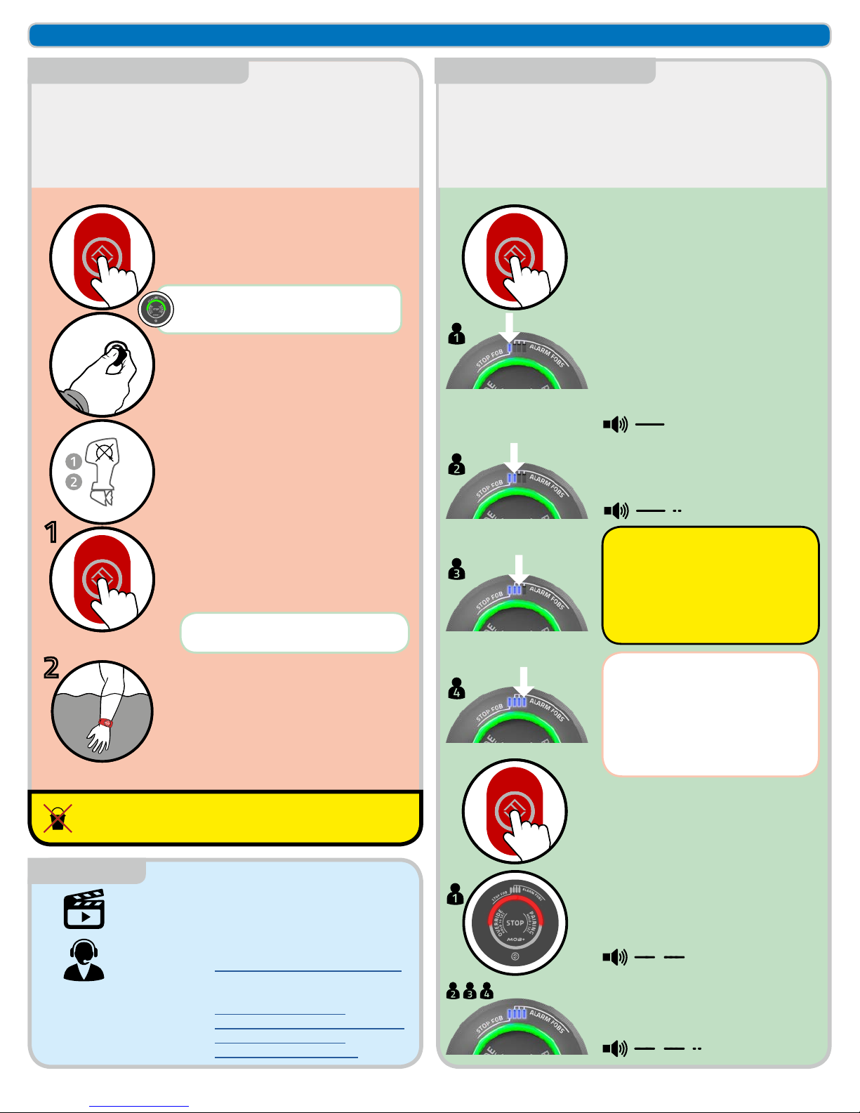
After proper installation, pair the xFOB and the xHUB as
described below. The xHUB remembers the 20 last paired
xFOBs. Pairing saves the ID of xFOBs in the memory of the
xHUB. Pairing is only done the rst time you use an xFOB
with an xHUB. Remember, four xFOBs can be connected at
the same time. One as a STOP FOB, three as ALARM FOBs.
Pairing is only necessary the rst time you
use your MOB+. Press and hold the button
on your xHUB.
HOLD 3 SEC
Immediately after releasing the button on
the xHUB, press and hold the button on your
xFOB.
HOLD 3 SEC
2
Release the button when the xHUB starts
ashing blue and gives a sound signal
indicating Pairing Mode.
BLUE LIGHT
The xHUB will give a sound signal and a
green light to indicate a successful pairing.
GREEN LIGHT
xFOB INITIAL PAIRING
IMPORTANT
We recommend that the installation of the MOB+
in your boat is performed by skilled personnel
familiar with electric wiring, or by a professional
mechanic or electrician. This is to prevent any
malfunction of the device related to installation.
The installation is simple and below you will
nd a quick guide. See next page for wiring
instructions.
For more information, visit our website
www.fellmarine.com/support
YOUR ENGINE
Visit:
www.fellmarine.com/support
to nd wire diagram for your
engine.
Connect the signal wires to the
existing kill switch wires and the
power wires to power.
YOUR ENGINE
Drill a 2-1/16” / 52mm hole in a
suitable place adjacent to the
drivers position.
2-1/16” / 52MM HOLE
Insert the xHUB to the pre-
drilled hole and tighten the nut.
MOUNT xHUB
Connect the cables and the
antenna to the xHUB.
CABLE & ANTENNA
!
Place the xHUB with the
antenna at least
~ 10” / 30cm from other
electronics equipment
transmitting EMI. The
antenna should be in as
free space as possible, but
where necessary it can be
bent up to 45 degrees.
1
INSTALLATION
IF YOU HAVE MULTIPLE ENGINES: SEE BELOW
MOBP17010 MOBP17011
INSTALLING MOB+ IN A METAL BOAT
If your helm is made out of conducting materials the wireless signals
from MOB+ may be degraded. The amount of signal degradation
experienced may vary from across boats and must be tested for each
case. If the signal is very poor you can install a separate external
antenna outside of your helm to increase the signal strength. Go to
www.fellmarine.com for more information.
DRILLING THE HOLE
The xHUB measures:
Ø=51,5mm / 2.03 in
Drill a 52mm / 2-1/16” hole
Be sure not to drill through any existing cables
or equipment mounted or situated on the
backside of your intended xHUB position! MOBP17013
xFOB BATTERY
xHUB will indicate low battery on the xFOB by
blinking the light bar respective to the connected
xFOB. Change the battery within 15 hours when
the light bar blinks. FELL recommends using
Panasonic or Sony CR2032 coin cell batteries.
Battery Life:
300h Active Use
MOBP17014
Do not push with
force on the button
when inserting the
xHUB. This may cause
damage to the device.
1
2
© FELL Technology AS Page 3/9
GENERAL USE AND INSTALLATION SECTION
MARCH 2018 REV200-0318
After installation, test the system as described below to
ensure installation is done correctly. Always make sure the
system is working properly before operating your vessel.
3
VERIFY INSTALLATION MOBP17012
The MOB+ allows for the pilot to be connected with his xFOB
as a STOP FOB and three more crew members or passengers
to be connected as ALARM FOBs. All xFOBs are universal and
can either be STOP FOB or ALARM FOB. The rst connected
xFOB on each boat trip will be assigned as the ”Master” and
become the STOP FOB. Successive connections automatically
become ALARM FOBs.
4
CONNECTION OF xFOBS MOBP17027
Click the button on your xFOB to connect. Click the button on your xFOB to connect.
Click the button on your xFOB to disconnect.
When connecting the rst xFOB it
becomes the STOP FOB. The STOP
FOB will automatically shut down the
engine(s) if the pilot falls overboard
and disconnect the ALARM FOBs.
Disconnecting the STOP FOB will
disconnect all FOBs regardless of
their connected state and shut down
the engine(s).
Disconnect an ALARM FOB individually
by clicking on the ALARM FOB.
When connecting the second, third and
fourth xFOBs they become ALARM FOBs.
CONNECT CONNECT
DISCONNECT
STOP FOB
STOP FOB
ALARM FOBs
ALARM FOBS
Start your engine.
START ENGINE
Test the MOB+ by disconnecting with the
xFOB or by submerging the xFOB.
Both described methods are equal in terms of
testing stop functionality.
TEST THE MOB+
Click the xFOB to stop the engine
-The system will now shut down the engine
and disconnect the wireless system.
DISCONNECT
1
Submerge the xFOB in the sea or the ocean
more than 4 inches.
-The system will now go into Man Over Board
mode and shut down the engine. After 6
seconds the xHUB will go into override mode.
Press the xHUB or xFOB to disconnect the
wireless system.
SUBMERSION
2
A bucket of water is not sucient to test the functionality
of MOB+. Test the system in the sea or ocean/lake.
RECONNECT AND RESTART THE ENGINE
BEFORE TESTING SUBMERSION
The xHUB will give a sound signal and
a GREEN light to indicate a successful
connection.
MOBP17015
SUPPORT
On www.fellmarine.com/videos you will nd
installation and user guide videos.
WATCH VIDEOS!
WE ARE HERE TO HELP YOU
Customer care:
Business
hours:
Email:
Web support:
Social Media:
Web:
www.fellmarine.com/customer-care
Monday-Friday 08:00am – 04:00
pm
https://www.fellmarine.com/support/
facebook.com/fellmarine
https://www.fellmarine.com
If any of the ALARM FOBs falls
overboard the xHUB will sound the
MOB Alarm, ashing on the xFOB
indication bar and ashing red on
the light circle. The alarm continues
until the STOP button on the xHUB is
pushed to disengage the alarm.
In an MOB event where the STOP
FOB falls overboard, remaining
passengers with an ALARM FOB
can choose to reconnect one of their
xFOBs rst to become the new STOP
FOB, successive connections will
become ALARM FOBs as normal.
MOBP17026
© FELL Technology AS Page 4/9
GENERAL USE AND INSTALLATION SECTION
MARCH 2018 REV200-0318
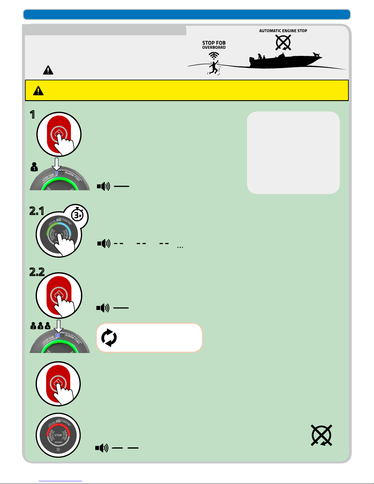
How to connect any of the ALARM FOBs with STOP function.
In the event that one (or more) of the ALARM FOBs with STOP
function goes overboard, it will trigger automatic engine shut
down.
Manual button press on an ALARM FOB connected with
STOP function (disconnect) will shut down the engine(s).
5
CONNECTING MULTIPLE FOBS WITH STOP FUNCTION MOBP17028
Click the button on your xFOB to connect.
CONNECT THE FIRST FOB
When connecting the rst xFOB it becomes the STOP FOB.
The STOP FOB will automatically shut down the engine(s) if
the pilot falls overboard and disconnect the all FOBs.
STOP FOB CONNECTED
Immediately after releasing the button on the xHUB, click the button on the
next xFOB to be connected as ALARM FOB with STOP function.
CONNECT ALARM FOB WITH STOP FUNCTION
Press and hold the button on the xHUB for 3 seconds to activate STOP function on the
next connecting ALARM FOB. The xHUB lights shifts between green and blue.
ACTIVATE STOP FUNCTION FOR THE NEXT CONNECTING ALARM FOB
1
2.1
2.2
Click the button on your xFOB to disconnect.
DISCONNECT
Disconnecting the STOP FOB or ALARM FOB with STOP function will shut down the
engine(s) and disconnect all FOBs regardless of their connected state.
DISCONNECTING STOP FOB OR ALARM FOB WITH STOP FUNCTION
NOTE: Any combination of
ALARM FOBs with or without
STOP function can be connected.
E.g. Connect a new ALARM FOB
with only ALARM functionality by
one click on the ALARM FOB,
going directly to step 2.2. without
rst performing step 2.1. above,
after a previous ALARM FOB
with STOP function has been
connected.
Repeat step 2.1 and 2.2 to
connect successive ALARM
FOBs with STOP function
If the STOP FOB or any of the connected ALARM FOBs with STOP function goes overboard, the xHUB will shut down the
engine(s), disconnect all connected FOBs and go into MOB mode. Anyone left on board can restart the engine as normal after 6
seconds without having to reconnect any FOBs or interact with the MOB+ system.
© FELL Technology AS Page 5/9
GENERAL USE AND INSTALLATION SECTION
MARCH 2018 REV200-0318
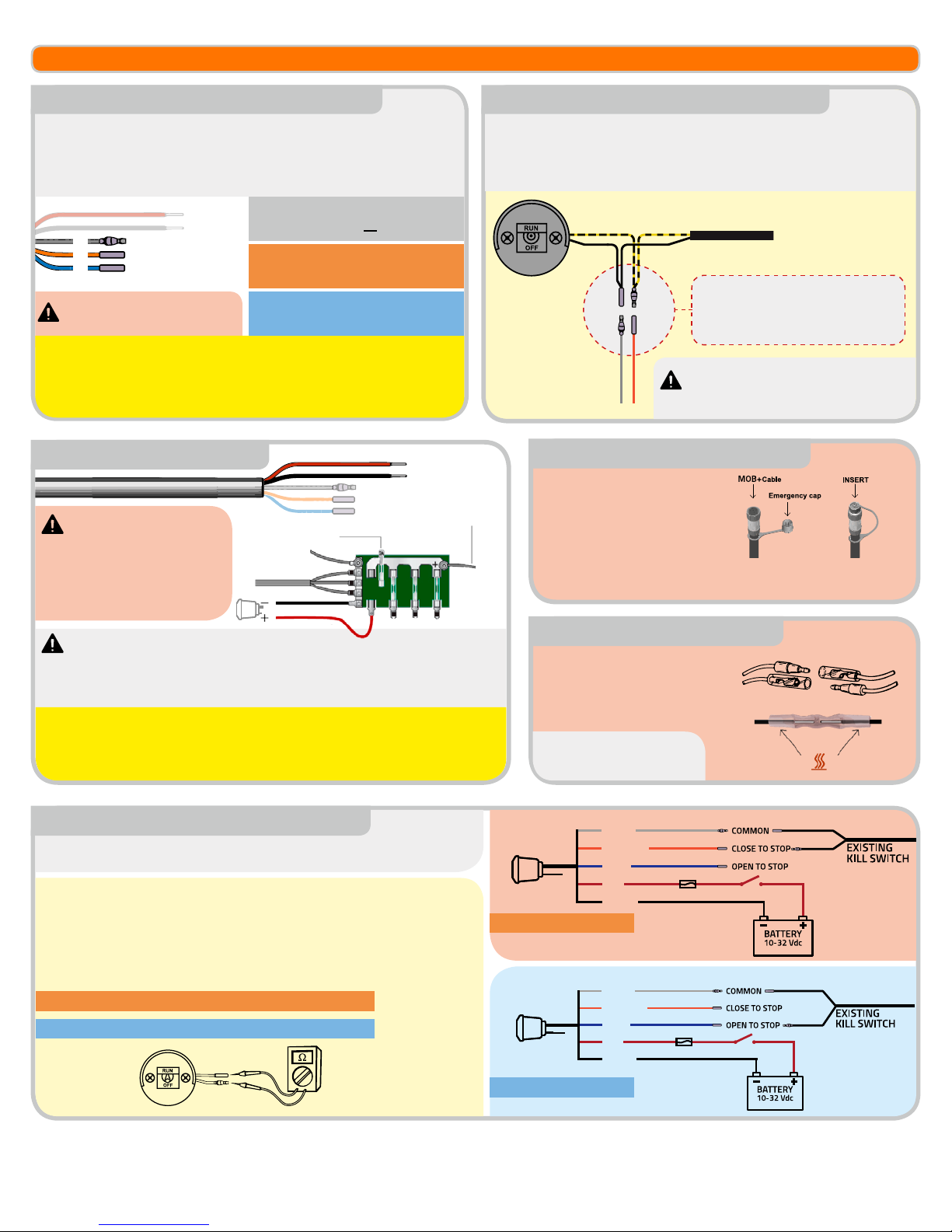
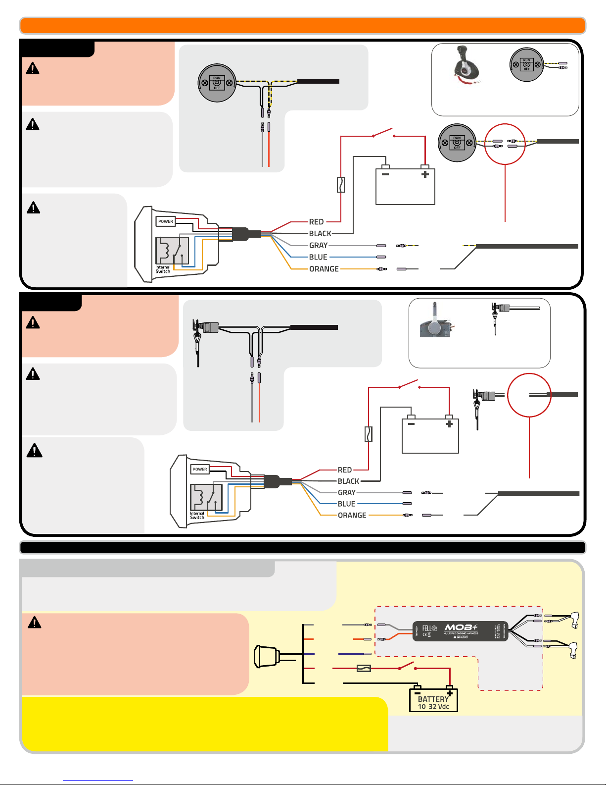
KEEP EXISTING OR MULTIPLE KILL SWITCH
Install the MOB+ inline with your existing kill switch or inline with
multiple kill switches by connecting it in parallel (e.g. multiple helm
positions with separate kill switches). The below picture shows an
example with Close to Stop connection as on Mercury engines.
To xHUB
To engine harness
CONNECTING KILL SWITCH SIGNAL WIRES
MOB+ xHUB has three kill switch signal wires. Only two of the three
wires should be used. Connect the two signal wires to the existing kill
switch wires in your boat. Most outboard engines have Close to Stop
(CS) kill switch system and use Gray and Orange wire for connection.
See wiring diagram below.
Before connecting the xHUB Signal Wires, you must verify which
kill switch principle is used by your engine manufacturer. See
section ”CLOSE TO STOP / OPEN TO STOP” below in this
manual if applicable. After installation, verify functionality as
in step 3 ”Verify Installation” above.
!
Make sure that all wire
connections are waterproof by
using marine grade butt splices or
similar when connecting wires.
Common (CMN) - Grey Wire
Use with Orange or Blue wire
Close to Stop (CS) - Orange Wire
Use with Grey Wire
Open to Stop (OS) - Blue Wire
Use with Grey Wire
Kill Switch Relay Max Current
Tolerance: 5A continuously
1
2
3
CMN (Common)
CS (Close to Stop)
OS (Open to Stop)
1
2
3
POWER WIRES (+/-)
All inline kill switches must be in
ON position and the MOB+ must be
connected to allow the engine(s) to run.
MOBP17016
MOBP17017
MECHANICAL SYSTEM OVERRIDE
WATERPROOF CONNECTIONS
Make sure that all wire
connections are waterproof by
using marine grade butt splices
or similar when connecting
wires.
20-16 AWG / 0.5 - 1.5 mm2
In the unlikely event that the
MOB+ System stops functioning.
Unplug the xHUB and plug the
emergency cap into the cable to
be able to drive your boat. The
emergency cap is located on the
cable supplied with the MOB+ xHUB.
Splice Wire Dimension:
MOBP17019
MOBP17020
CONNECTING POWER (+/-)
To MOB+ xHUB
Boat ground
1-3 A fuse
To 10 - 32 Vdc
boat supply
POWER (+)
GROUND (-)
FROM xHUB
Wire the xHUB to a circuit with a power switch to avoid battery drainage. The
xHUB has a power draw of 30mA in idle mode while connected to a power
source.
RECOMMENDED
Poor power connection may
cause voltage drop below 7V
e.g. when engine is cranked.
This may cause xHUB to reset
and inhibit engine start.
IMPORTANT
MOBP17018
Min. Voltage: 7V - Below this voltage the unit will turn o
and you will not be able to start your engine.
Max. Voltage: 32V Do not exceed this voltage because this can
damage the MOB+ xHUB and void the warranty.
!
CLOSE TO STOP / OPEN TO STOP
Main Power Switch
RED
BLACK
GRAY
BLUE
ORANGE
Fuse 1A
Main Power Switch
RED
BLACK
GRAY
BLUE
ORANGE
Fuse 1A
General wiring diagrams showing wiring connections for Close to
Stop and Open to Stop kill switch principle.
Testing your kill switch principle
Test the kill switch principle by connecting a multimeter to both
cables from the existing mechanical kill switch. Set multimeter to
measure resistance and the kill switch is in the position which the
engine will not run (cord is not inserted in the mechanical kill switch).
MOBP17024
MOBP17025
Close to 0 (zero) resistance: Close to stop (CS)
Innite resistance measured: Open to stop (OS)
CLOSE TO STOP
OPEN TO STOP
© FELL Technology AS Page 6/9
WIRING SECTION
MARCH 2018 REV200-0318
YAMAHA
*The wire connections are the same for
the external kill switch and kill switch
mounted in the throttle casing.
Battery
Close to Stop
Main Power Switch
Fuse
1-3 A 10 - 32VDC
From existing
Kill Switch
Black/White
Black
Switch position in
inactive mode e.g.
engine not running.
5-pin IP67
Connector
Max Internal Switch load: <5A
Min. Power Voltage: 7V
-Below this voltage the unit will
turn o.
To engine
harness
To xHUB
Parallel
Connection
Inline with existing kill switch:
RECOMMENDED
RECOMMENDED
Make sure that all
wire connections are
waterproof by using
marine grade butt
splices or similar when
connecting wires.
Avoid cutting or modifying original kill
switch wiring
IMPORTANT
MOB+ xHUB
MOBP17022
If keeping mechanical kill switch
in place, connect MOB+ in parallel
with mechanical kill switch to
avoid potential danger from a non-
functional mechanical kill switch.
MERCURY
To engine
harness
To xHUB
Parallel
Connection
Inline with existing kill switch:
*The wire connections are the same for
the external kill switch and kill switch
mounted in the throttle casing.
Battery
Close to Stop
Main Power Switch
Fuse
1-3 A 10 - 32VDC
From existing
Kill Switch
Black/Yellow
Black
Switch position in
inactive mode e.g.
engine not running.
Max Internal Switch load: <5A
Min. Power Voltage: 7V
-Below this voltage the unit will
turn o.
5-pin IP67
Connector
RECOMMENDED
If keeping mechanical kill switch
in place, connect MOB+ in parallel
with mechanical kill switch to
avoid potential danger from a non-
functional mechanical kill switch.
RECOMMENDED
Make sure that all
wire connections are
waterproof by using
marine grade butt
splices or similar when
connecting wires.
Avoid cutting or modifying original kill
switch wiring
IMPORTANT
MOB+ xHUB
MOBP17021
MOB+ MULTIPLE ENGINE HARNESS (MOB+ MEH)
R E D
BLA C K
G R A Y
B L U E
O R ANG E
Fuse 1A Main Power Switch
COLOR ID:
White = Signal
Black = Ground
!*Multiple Engine Harness kit includes User
Manual, please read this carefully before
installing this product.
Part name: MOB+ Multiple Engine Harness
P/N: (F-A/N): 72.380.401
Availability: FELL Marine dealers and buy.fellmarine.com
For multiple outboard installations, the black (-) battery cable of each engines starter motor
ground circuit, MUST BE connected to each other by a common circuit (cable) capable of
carrying the starting current of each engines starter motor. (i.e. A locally obtained battery
cable connected between the negative (-) terminal of each outboards cranking battery.)
CAUTION
This product is designed to be used in conjunction with the MOB+ xHUB to stop
multiple engines simultaneously for multiple outboard installations. The MOB+
xHUB should be installed prior to installation of this Multiple Engine Harness.
IMPORTANT
• WHITE wire on MOB+ MEH is signal wire; each engines signal
wire must be connected to the WHITE wire on the MOB+ MEH.
• BLACK wire on the MOB+ MEH is GND wire; each engines
GND wire must be connected to the BLACK wire on the MOB+
MEH.
• Connect WHITE and BLACK wires in pairs as bundled on
the MEH kit.
MOBP17023
FOR OTHER ENGINE BRANDS SEE WWW.FELLMARINE.COM/SUPPORT
© FELL Technology AS Page 7/9
WIRING SECTION
MARCH 2018 REV200-0318

Disclaimer
Always boat responsibly. Before starting, know your boat and waterway rules. Always follow your
boat manufacturer’s procedures of operation. Never overload the boat and be sure to wear your
life jacket at all times. Check your boat for all required safety equipment and never operate a
boat under the inuence of alcohol. Check your local weather forecast before
leaving the dock and always provide a oat plan to your marina, member of your family or friend.
In no event shall FELL Technology AS and its subsidiaries and/or its suppliers, agents or aliates
be liable for any direct, indirect, punitive, incidental, special consequential damages, to property
or life, whatsoever arising out of or connected with the improper installation, misuse,
improper maintenance, self-repair, or tampering of our products.
EMC Installation Guidelines
FELL equipment and accessories are designed to the best industry standards for use in the
recreational marine environment. Their design and manufacture conforms to the appropriate
Electromagnetic Compatibility (EMC) regulations, but correct installation is required to ensure
that performance is not compromised.
The guidelines given here describe the conditions for optimum EMC performance, but it is rec-
ognized that it may not be possible to meet all of these conditions in all situations. To ensure the
best possible conditions for EMC performance within the constraints imposed by any location,
always ensure the maximum separation possible between dierent items of electrical equipment.
For optimum EMC performance, it is recommended that wherever possible:
• FELL equipment and the cables connected to it are:
• At least 3 ft. (1 m) from any equipment transmitting or cables carrying radio signals e.g. VHF
radios, cables and antennas. In the case of SSB radios, the distance should be increased to
7 ft. (2 m).
• More than 7 ft. (2 m) from the path of a radar beam. A radar beam can normally be assumed to
spread 20 degrees above and below the radiating element.
• If possible the product is supplied from a separate battery from that used for engine start.
Power supply voltages below the minimum specied for a product, and starter motor transients,
can cause the product to reset. This will not damage the product, but may cause the loss of
some information and may change the operating mode.
• FELL specied cables are used. Cutting and rejoining these cables can compromise EMC
performance and must be avoided unless doing so is detailed in the installation manual.
Important information and caution
Read all instructions carefully before use of this product.
FELL Marine equipment and accessories are designed to the best industry standards for use in
the recreational marine environment. Their design and manufacture conforms to the appropriate
Electromagnetic Compatibility (EMC) regulations, but correct installation is required to ensure
that performance is not compromised. Please see section EMC Installation Guidelines in the
User Manual for optimum EMC conditions.
Within the wireless range MOB+ will not shut down the engine automatically e.g. if you fall in
your boat within the wireless range the engine will not stop automatically. In this event, you
can shut down the engine by pressing the button on your MOB+ xFOB or on the MOB+ xHUB.
Always check your wireless range before use.
Make sure that the system is working properly before leaving the dock. Refer to the next page
in this User Manual for instructions on how to use the system and information about normal
system operations.
Always make sure to check the battery level sign on the xHUB before driving the boat. Confer
with section xFOB Battery in this User Manual to check how many hours there are left of battery
life on the xFOB.
Never attempt fast speed or dangerous maneuvers of the boat, especially if battery level is low
on the xFOB. Battery depletion of xFOB can cause sudden engine stop and result in loss of
control or maneuverability of the boat.
Never attempt any service of inside components in either the xHUB or the xFOB.
Warranty, Important Product- and Safety Information
For products sold in the US/CAN
Failure to avoid the following potentially hazardous situations could result in an accident or
collision resulting in death or serious injury.
Disclaimer
By using this device you agree upon all the following guidelines and information provided in
this document. Read all instructions carefully before using this device. Always boat responsibly.
Before starting, know your boat and waterway rules. Always follow your boat manufacturer’s
procedures of operation. Never overload the boat and be sure to wear your life jacket at all
times. Check your boat for all required safety equipment and never operate a boat under the
inuence of alcohol. Check your local weather forecast before leaving the dock and always
provide a oat plan to your marina, member of your family or friend. In no event shall FELL and
its subsidiaries and/or its suppliers, agents or aliates be liable for any direct, indirect, punitive,
incidental, special consequential damages, to property or life, whatsoever arising out of or
connected with the improper installation, use, misuse, improper maintenance, self-repair, or
tampering of our products.
Marine Operation Warnings
• You are responsible for the safe and prudent operation of your vessel. This device is a
tool to enable you to enhance your safety while operating your vessel. It does not relieve
you from the responsibility of safely operating your vessel. Avoid navigational hazards and
never leave the helm unattended.
• Always drive the boat carefully and in accordance with local laws.
• Use this device only as a safety aid. This device does not replace the cord based kill
switch, and should be used at your own discretion and responsibility, knowing that in the
event that you fall in your vessel the system may not automatically shut down your engine.
• This device will shut down your engine and give an alarm signal when you are out of
wireless range or falls into the water within 2 seconds. Within the wireless range this
device will not shut down the engine automatically e.g. if you fall in your boat within the
wireless range the engine will not stop automatically. In this event, you can shut down the
engine by pressing the button on your MOB+ xFOB or on the MOB+ xHUB. Always check
your wireless range before use. The wireless range in air may vary from 5 – 40 meters (15
- 120 feet) depending on the wireless environment surrounding your vessel.
• Make sure that the system is working properly before leaving the dock. Refer to the section
Verify Installation in this User Manual for instructions on how to use the system and
information about normal system operations.
• Always make sure to check the battery level sign on the xHUB before operating your
vessel. Confer with section xFOB Battery in this User Manual to check how many hours
there are left of battery life on the xFOB.
• Never attempt fast speed or dangerous maneuvers of the boat, especially if battery level is
low on the xFOB. Battery depletion of xFOB can cause sudden engine stop and result in
loss of control or maneuverability of the boat.
• Do not leave your xFOB in the boat unobserved, this to prevent easy theft of the boat if
the ignition key is also situated in the vessel. Please refer to the engine manufacturer for
information regarding ignition and starting procedure of the engine.
© FELL Technology AS, Nedre Storgate 46, N-3015, Drammen, Norway. FELL®, WiMEA®,
WiMEA Protocol, MOB+, xHUB, xFOB, xTAG and its logos are trademarks of FELL Technology
AS, its subsidiaries and aliates. The shape and design of this product are a trademark of FELL
Technology AS, subsidiaries and aliates. NMEA®, NMEA 2000®, and the NMEA 2000 logo are
registered trademarks of the National Marine Electronics Association. All other trademarks or
registered trademarks are the property of their respective owners. Designed in Norway. Made in
China and Taiwan. All rights reserved. Product features, appearances and specications may be
subject to change without notice. Read all instructions carefully before use. Visit www.fellmarine.
com/support for complete Owner’s Manual. Please retain this information for future reference.
Changes or modications to the equipment not expressly approved by the party responsible for
compliance could void the user’s authority to operate the equipment.
This device complies with Part 15 of the FCC Rules. Operation is subject to the following two
conditions: (1) this device may not cause harmful interference, and (2) this device must accept
any interference received, including interference that may cause undesired operation.
Note: This equipment has been tested and found to comply with the limits for a Class B digital
device, pursuant to part 15 of the FCC Rules. These limits are designed to provide reasonable
protection against harmful interference in a residential installation. This equipment generates,
uses and can radiate radio frequency energy and, if not installed and used in accordance with
the instructions, may cause harmful interference to radio communications. However, there is no
guarantee that interference will not occur in a particular installation. If this equipment does cause
harmful interference to radio or television reception, which can be determined by turning the
equipment o and on, the user is encouraged to try to correct the interference by one or more of
the following measures:
—Reorient or relocate the receiving antenna.
—Increase the separation between the equipment and receiver.
—Connect the equipment into an outlet on a circuit dierent from that to which the receiver is
connected.
—Consult the dealer or an experienced radio/TV technician for help.
MOB+ xHUB: This device complies with FCC RF radiation exposure limits set forth for an
uncontrolled environment. The antenna used for this transmitter must be installed to provide a
separation distance of at least 20 cm from all persons and must not be co-located or operating in
conjunction with any other antenna or transmitter.
MOB+ xFOB: This device is exempted from FCC SAR testing since the RF Output Power is
below the exemption limit.
California ONLY: Perchlorate Material - special handling may apply,
See: http://www.dtsc.ca.gov/hazardouswaste/perchlorate
Déclaration d’exposition aux radiations:
Cet équipement est conforme aux limites d’exposition aux rayonnements IC établies pour un
environnement non contrôlé. Cet équipement doit être installé et utilisé avec un minimum de 20
cm de distance entre la source de rayonnement et votre corps.
Radiation Exposure Statement
This equipment complies with IC radiation exposure limits set forth for an uncontrolled environ-
ment. This equipment should be installed and operated with minimum distance 20 cm between
the radiator & your body.
This device complies with Industry Canada licence-exempt RSS standard(s). Operation is
subject to the following two conditions: (1) this device may not cause interference, and (2) this
device must accept any interference, including interference that may cause undesired operation
of the device. Le présent appareil est conforme aux CNR d’Industrie Canada applicables aux
appareils radio exempts de licence. L’exploitation est autorisée aux deux conditions suivantes
: (1) l’appareil ne doit pas produire de brouillage, et (2) l’utilisateur de l’appareil doit accepter
tout brouillage radioélectrique subi, même si le brouillage est susceptible d’en compromettre le
fonctionnement.
Voir www.fellmarine.com/support pour des informations
importantes, consignes d’installation CEM, la garantie et exclusions
en français.
Ver www.fellmarine.com/support para obtener información importante,
pautas para la instalación de EMC la garantía y limitaciones de
responsabilidad en Español.
Siehe www.fellmarine.com/support für wichtige Informationen,
EMV-Installationsrichtlinien Gewährleistung und Haftungsausschlüsse
in deutscher Sprache.
© FELL Technology AS Page 8/9MARCH 2018 REV200-0318
Other safety Considerations
Small parts contained in your device and its accessories may present a choking hazard to small
children. Personal medical devices, such as pacemakers, may be sensitive to magnetic and
electromagnetic elds. Since this device contain magnets and emit electromagnetic elds, they
should be kept at least 30 cm from any personal medical device. If any interference is observed,
consult with your physician before resuming use. Items with magnetically-stored data, such as
credit cards and hard drives, may also be sensitive to magnetic or electromagnetic elds, and
should not be placed near this device.
CE Declaration of Conformity
FELL equipment and accessories are designed to the best industry standards for use in the
recreational marine environment. Their design and manufacture conforms to the appropriate
Electromagnetic Compatibility (EMC) regulations, but correct installation is required to ensure
that performance is not compromised. Please see section EMC Installation Guidelines in the
User Manual for optimum EMC conditions. Products sold in the EU/EEA is in compliance with the
essential requirements and other relevant provisions of R&TTE Directive 1999/5/EC.
CE SAR Compliance
For products sold in the EU/EEA this device meets the EU requirements (1999/519/EC) on the
limitation of exposure of the general public to electromagnetic elds by way of health protection.
The limits are part of extensive recommendations for the protection of the general public. These
recommendations have been developed and checked by independent scientic organizations
through regular and thorough evaluations of scientic studies. The unit of measurement for the
European Council’s recommended limit for mobile devices is the ”Specic Absorption Rate”
(SAR), and the SAR limit is 2.0 W/ kg averaged over 10 gram of tissue. It meets the require-
ments of the International Commission on Non-Ionizing Radiation Protection (ICNIRP).
Wireless Safety and Compliance
Turn your wireless connection o in areas where wireless use is forbidden or when it may cause
interference or danger. Some specic situations are described below. In general, you should not
use your FELL devices with your wireless connection turned on any place you are not allowed
to use a cellular device. To prevent possible interference with aircraft systems, aviation agencies
require you to have permission from a crew member to use your device’s wireless service. We
do not recommend to use FELL devices when ying.
Battery Information
Standard battery used in this device from manufacturing is:
Panasonic – BATTERY LITHIUM COIN 3V 20MM CR2032. Lead free / RoHS compliant by
exemption.
Manufacturer Part Number: CR2032L/BE.
Panasonic CR2032L/BE Specication Datasheet for battery can be found here: https://s3-eu-
west-1.amazonaws.com/generalweb/productinfo/panasonic_cr2032_datasheet.pdf
Panasonic CR2032L/BE MSDS Safety Datasheet can be found here: https://s3-eu-west-1.
amazonaws.com/generalweb/productinfo/panasonic_cr2032_productsafety.pdf
FELL recommend using the above battery when changing battery in MOB+ xFOB device, to
ensure wireless connection quality and battery life performance.
Limited Warranty
This FELL product is warranted to be free from defects in materials or workmanship for two years
from the date of purchase. Within this period, FELL will, at its sole option, repair or replace any
components that fail in normal use. Such repairs or replacements will be made at no charge to the
customer for parts or labor, provided that the customer shall be responsible for any transportation
cost. This warranty does not apply to: (i) cosmetic change, such as scratches, nicks and dents;
(ii) consumable parts, such as batteries, unless product damage has occurred due to the defect
in materials or workmanship; (iii) damage caused by accident, abuse, misuse, water, ood, re, or
other acts of nature or external causes; (iv) damage caused by service performed by anyone who
is not an authorized service provider of FELL, or (v) damage to a product that has been modied or
altered without the written permission of FELL, or (vi) damage to a product that has been connected
to power and/or data cables that are not supplied by FELL. In addition, FELL reserves the right to
refuse warranty claims against products or services that are obtained and/or used in contravention
of the laws of any country. Repairs have 180 day warranty. If the unit sent in is still under its original
warranty, then the new warranty is 180 days or to the end of the original two year warranty, depend-
ing on which is longer. For specic instructions about how to obtain warranty service for your device,
please contact FELL support. THE WARRANTIES AND REMEDIES CONTAINED HEREIN ARE
EXCLUSIVE AND IN LIEU OF ALL OTHER WARRANTIES EXPRESS, IMPLIED, OR STATUTORY,
INCLUDING ANY LIABILITY ARISING UNDER ANY WARRANTY OF MERCHANTABILITY OR
FITNESS FOR A PARTICULAR PURPOSE, STATUTORY OR OTHERWISE. THIS WARRANTY
GIVES YOU SPECIFIC LEGAL RIGHTS, WHICH MAY VARY FROM STATE/COUNTRY TO STATE/
COUNTRY. IN NO EVENT SHALL FELL, ITS SHAREHOLDERS, BOARD OF DIRECTORS, OR
EXECUTIVE LEADERS BE LIABLE FOR ANY INCIDENTAL, SPECIAL, INDIRECT, OR CONSE-
QUENTIAL DAMAGES, WHETHER RESULTING FROM THE USE, MISUSE, OR INABILITY TO
USE THIS PRODUCT OR FROM DEFECTS IN THE PRODUCT. SOME STATES/COUNTRIES
DO NOT ALLOW THE EXCLUSION OF INCIDENTAL OR CONSEQUENTIAL DAMAGES, SO
THE ABOVE LIMITATIONS MAY NOT APPLY TO YOU. SOME JURISDICTIONS DO NOT ALLOW
LIMITATIONS ON HOW LONG A STATUTORY OR IMPLIED WARRANTY LASTS, SO THE ABOVE
LIMITATION MAY NOT APPLY TO YOU. This limited warranty gives you specic rights. You may
have additional rights under applicable law, and this limited warranty does not aect such rights.
FELL retains the exclusive right to repair or replace (with a new or newly-overhauled replacement
product) the device or software or oer a full refund of the purchase price at its sole discretion.
SUCH REMEDY SHALL BE YOUR SOLE AND EXCLUSIVE REMEDY FOR ANY BREACH OF
WARRANTY. To obtain warranty service, contact your local FELL authorized dealer or call FELL
Support for shipping instructions and an Return Ticket Number. Securely pack the device and a copy
of the original sales receipt, which is required as the proof of purchase for warranty repairs. Write
the tracking number clearly on the outside of the package. Send the device, freight charges prepaid,
to your nearest FELL address. See www.fellmarine.com to nd your nearest address for return or
contact your local FELL dealer.
ONLINE AUCTION PURCHASES: Products purchased through online auctions are not eligible for
rebates or other special oers from FELL warranty coverage. Online auction conrmations are not
accepted for warranty verication. To obtain warranty service, an original or copy of the sales receipt
from the original retailer is required. FELL will not replace missing components from any package
purchased through an online auction.
FOR INTERNATIONAL PURCHASES: A separate warranty may be provided by international
distributors for devices purchased outside Norway or the United States depending on country. If
applicable, this warranty is provided by the local in-country distributor and this distributor provides
local service for your device. Distributor warranties are only valid in the area of intended distribution.
FOR AUSTRALIAN CONSUMERS: Our goods come with guarantees that cannot be excluded
under the Australian Consumer Law. You are entitled to a replacement or refund for a major failure
and for compensation for any other reasonably foreseeable loss or damage. You are also entitled to
have the goods repaired or replaced if the goods fail to be of acceptable quality and the failure does
not amount to a major failure. Goods presented for repair may be replaced by refurbished goods of
the same type rather than being repaired. Refurbished parts may be used to repair the goods.
Warranty provider
FELL Technology AS Nedre Storgate 46, N-3015 Drammen,Norway
Org.No: 912 282 554 - Website: www.fellmarine.com - Tel: +47 32 82 82 80
Support: [email protected]
Additional information
www.fellmarine.com
www.fellmarine.com/support
WARNING: CHOKING HAZARD
Small parts. Not for children under 3 years
WARNING: KEEP AWAY FROM CHILDREN
Danger if swallowed.
R-NZ
Norway
FELL Technology AS
Nedre Storgate 46
N-3015, Drammen
www.fellmarine.com
Product contains CR2032 Lithium Metal Coin Cell Battery
Product category: Marine electronics
MOB+ xFOB Model: GU80115
FELL is a proud member of the following leading
marine industry organizations:
Wireless System Powered By:
MOB+ xHUB Model: BU80115
For products sold in EU/EEA/NZ
MOB+ xFOB Model: GU90115-AU
MOB+ xHUB Model: BU90115-AU
For products sold in AU
MOB+ xFOB Model: GU90115 FCC ID: 2AFOZGU90115 IC: 20622-GU90115
MOB+ xHUB Model: BU90115 FCC ID: 2AFOZBU90115 IC: 20622-BU90115
For products sold in US/CA
Designed in Norway, Printed in China
Tested to comply with FCC standards.
Tested and certied to comply with the
CE Directive, R&TTE, RCM, R-NZ.
Tested and certied to comply with the
RCM and FCC Standards.
Recycling
In some areas, the disposal of certain electronic devices is regulated. Make sure you dispose of
or recycle all FELL devices in accordance with your local laws and regulations.
Other Electronic Devices
FELL devices generates, uses, and radiate radio frequency (RF) energy and, if not used in
accordance with its instructions, may cause interference to radio communications and electronic
equipment, i.e. if hardware or software is being tampered with or the device has become broken.
FELL devices are designed and manufactured to only communicate with FELL devices. External
RF signals may aect improperly installed or inadequately shielded electronic operating systems,
entertainment systems, and personal medical devices. While most modern electronic equipment
is shielded from external RF signals, if in doubt, check with the manufacturer or contact FELL
for support. For personal medical devices (such as pacemakers and hearing aids), consult with
your physician or the manufacturer to determine if they are adequately shielded from external
RF signals, showing this user guide to the respective physician or manufacturer. In the unlikely
event that you experience interference with other electronic devices, please contact customer
support on: www.fellmarine.com/support or contact the manufacturer of the respective electronic
device. There are some places where RF signals could constitute a hazard, such as health care
facilities, and construction sites. If you are not sure, look around for signs indicating that two-
way radios or cell phones should be turned o.
Patent notice
The FELL devices and/or methods used in association with the FELL devices may be covered by
one or more patents or pending patent applications.
© FELL Technology AS Page 9/9MARCH 2018 REV200-0318
This manual suits for next models
7
Table of contents
Popular Marine Equipment manuals by other brands


Raymarine
Raymarine hsb2 PLUS Series Owner's handbook

Shenzhen Waytronic Electronics
Shenzhen Waytronic Electronics MicroSound V16.00 quick start guide

knudsen
knudsen Chirp 3260 Troubleshooting and Maintenance Manual

Raymarine
Raymarine autopilot ST4000+ quick reference

Valeport
Valeport MIDAS Surveyor Operation manual

Humminbird
Humminbird HELIX GPS installation guide