Eaton Crouse-hinds series User manual

October 2016
INS DB5 Rev 9
Instruction sheet
MTL process alarm equipment
RTK DB5
MTL intrinsically safe sounder type DB-5
Eaton Electric Limited,
Great Marlings, Butterfield, Luton
Beds, LU2 8DL, UK.
Tel: + 44 (0)1582 723633 Fax: + 44 (0)1582 422283
E-mail: [email protected]
www.mtl-inst.com
© 2016 Eaton
All Rights Reserved
Publication No. INS DB5 Rev 9
October 2016
Description
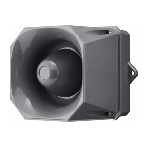
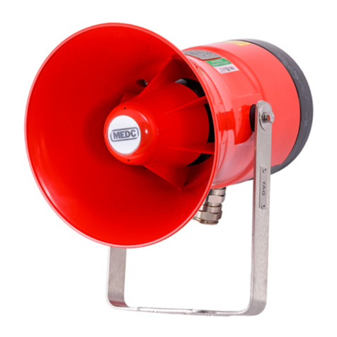
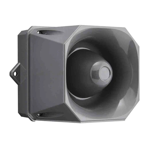
The RTK DB5 sounder is a strong, lightweight warning
sounder, CENELEC certified to Ex II 1G EExia IIC T4 (Ta
-20°C to 55°C) with 26 user-selectable tones, and an
output level of over 100dB.
Also available certified to CSA, FM standards and for use
in mines.
Connection details
1 +ve common
2 +ve common
3 -ve 1st tone
4 -ve 1st tone
5 -ve 2nd tone
6 -ve 2nd tone
To generate the first tone simply connect supply +ve to
terminals 1 or 2, and supply –ve to terminals 3 or 4. To
generate the second tone simply connect supply +ve to
terminals 1 or 2, and supply –ve to terminals 5 or 6. Note,
if +ve is connected to 2nd sound, it will permanently
damage the sounder.
Each terminal is duplicated and internally connected to
allow for ease of connecting subsequent horns or end-of-
line (EOL) resistors.
Installation
Mounting
The sounder should be positioned using the two available
fixing holes in the base. It is recommended that stainless
steel nuts and bolts be used if the environment is corrosive.
The sounder will operate in any attitude, from horizontal to
vertical. However, it is important to note that the alignment
and mounting of the sounder should ensure that:
• Dust or debris cannot lodge in the re-entrant horn.
Water from hose’s, jets or rain cannot settle in the
re-entrant horn.
• The sounder should be installed in accordance with
certified parameters.
Removing and replacing the cover
Remove the cover/horn of the sounder by rotating the
top of the sounder anti-clockwise, and pulling the cover/
horn gently away from the base. Replacing the cover/
horn is a reverse process of the above, but care should
be taken to ensure that the seal is securely located in its
groove during re-assembly.
Wiring
Cable termination should be in accordance with
specifications applying to the application. It is
recommended that all cables and cores should be
fully identified. Ensure that only the correct glands are
used and that the assembly is shrouded. Refer to the
connection details below.
The twinned-pair inlet terminals and deep base are
convenient for looping to other circuits or for siting end-
of-line resistors. The base has three knockouts, two on
the side and one on the base, to accommodate a 20mm
conduit or M20 cable glands. The units are polarised and
a chain may be fitted with an “end of line” resistor for
reverse polarity testing and to permit line monitoring.
Recommended cable
0.5 to 2.5mm2with earthed screen and insulating
sheath. Cable parameters are determined by the output
parameters of the interface selected.
Safe area use
In safe areas, the sounders can be powered directly from
24VDC/12VDC. The absence of any current limitation
increases the output by approx 4dB.
Sound
The sound level for each of the individual tones in shown
in Table 2. This is assuming one DB5 set at full volume,
driven from a suitable IS interface. Where two sounders
are driven from the same IS source, the output will
decrease by 1.5dB. Three sounders will decrease by
2.2dB. A single turn potentiometer is provided to reduce
the volume level by a minimum of 15dB.
RTK DB5
October 2016
32 INS DB5 Rev 9
Intrinsically safe specification
Certification
Certified by BASEEFA to Ex II 1G, EEx ia IIC T4
(Ta-20°C to 55°C) to CENELEC standards.
Certificate No. BAS00ATEX1259
Location
IIC T4, installation can be in any zone.
Safety parameters
DB5:
Ui = 28V, Ii = 28mA, Pi = 0.81W
Ci = 0, Li = 20mH + 1000Ω
The DB5 sounder has an internal resistance Ri of 1000Ω
which ensures that the input current limit Ii for inductive
safety is not exceeded
DB5-12:
Ui = 15.7V, Ii = 37mA, Pi = 0.56W
Ci = 0, Li = 20mH + 325Ω
The DB5-12 sounder has an internal resistance Ri of
325Ω which ensures that the input current limit Ii for
inductive safety is not exceeded
Supply
DB5:
Min/max at terminals = 15-28VDC
Current (through interface) = 14mA
DB5-12:
Min/max at terminals = 9.6-15VDC
Current (through interface) = 12mA
EMC compliance
Immunity to EN50082-2:1995
Emissions to EN50081-2:1994
Terminals
For conductors up to 2.5mm2
DB5:
Zener barrier interfaces
Suitable models are: 24v version MTL7728+, 12v version
MTL7715+
Galvanic isoloator interfaces
Suitable models are: MTL5025
DB5-12:
Zener barrier interfaces
Suitable model: MTL7715+
Weight
300g
Environment
Operating temperature-20 to +55°C
Storage temperature-40 to +80°C
Humidity 5-95% RH, non-condensing
Protection IP65
Construction
ABS enclosure with encapsulated electronic module.
Colour red.
Electrostatic risk
By virtue of it’s shape, design and position of use, it is not considered to be an electrostatic risk, however, the
apparatus must not be installed in a position where it may be subjected to an excessive air flow that might cause an
electrostatic build-up.

32
RTK DB5
October 2016
INS DB5 Rev 9
Mining certification
Certification
Certified by EECS to Ex I M1 EEx ia 1
Certificate No: MECS01ATEX4260
Intrinsically safe parameters
DB-5-M-012:
Ui = 14.4V, Uo = 14.4V
Ci = 0, Li = 0
FM certification
Certification
Intrinsically Safe for Class I, Division 1, Groups A,B,C
and D.
Certificate No: J.I 3008604
Entity parameters for DB5 (24V version):
Vmax = 28VDC, Imax = 147mA, Pmax = 810mW,
Ci = 0, Li = 0
Entity parameters for DB5-12 (12V version):
Vmax = 15.7VDC, Imax = 150mA, Pmax = 560mW,
Ci = 0, Li = 0
CSA certification
Certification
Certified by CSA to standard numbers 0, 0.4, 0.5, 25, 30,
205. Class 1 Groups A,B,C and D
Certificate No: 79122
Supply
Min/max at terminals = 15-28VDC
Current (through interface) = 14mA
Environment
Operating temperature-20 to +55°C
Storage temperature-40 to +80°C
Humidity 5-95% RH, non-condensing
Protection IP65
Zener barrier interfaces
Contact Eaton for suitable MTL models
Galvanic isoloator interfaces
Contact Eaton for suitable MTL models

RTK DB5
October 2016
54 INS DB5 Rev 9
Installation diagram
Notes:
1. Any shunt zener diode safety barrier or galvanic isolator, certified by an EEC approved body to [EEx ia] IIC, having
the following maximum output parameters:
DB5-24:
Uo = 28V, Io = 147mA, Po = 0.81W
DB5-12:
Uo = 15.7V, Io = 150mA, Po = 0.56W
2. Other barriers having lower values than these are permitted.
3. In any safety barrier used the output current must be limited by a resistor “R” such that:
Io = Uo / R
4. The capacitance and inductance of the hazardous area cable must not exceed the values quoted in the certificate
for the particular barrier/isolator used. See table 1. If the inductance to resistance ratio (L/R) of the cable is higher
than the ratio of the barrier/isolator, the maximum length that can be connected to the interface has to be
calculated.
5. The installation must comply with the appropriate national installation requirements e.g. in the U.K.
BSEN 60079-14:1997.
6. The circuit in the hazardous area must be capable of withstanding 500V RMS to earth or frame for one minute
when using zener diode safety barriers.
Cable parameters
Group Capacitance μF Inductance μH L/R ratio μH/Ω
Typical 28V / 300Ω zener barrier
IIC 0.083 4.2 55
IIB 0.65 12.6 165
IIA 2.15 33.6 440
Table 1
Sounder type DB5 to
Certificate
BAS00ATEX1259
Ex II 1 G
EEx ia IIC T4
Hazardous area Non-hazardous area
One zener diode safety barrier
See notes 1-3
Or galvanic isolation interface
See note 4-6
Non-hazardous area apparatus
which is unspecified except that it
must not be supplied from nor
contain under normal or abnormal
conditions, a source or potential
with respect to earth in excess of
250VAC RMS or 250VDC.

54
RTK DB5
October 2016
INS DB5 Rev 9
Operating instructions
Tone selection
The required tone should be selected by referring to table 2 below. The 5-way DIL switches on the PCB should then
be set to the code as shown (1 being equivalent to the on position, 0 being equivalent to the off position).
Sound level
The output sound level shown is for a sounder powered from an RTK WIS1211 interface or from an RTK S951 barrier,
fed by 24VDC.
Tone
no Tone frequency 2nd
tone
DIL switch
setting 12345
Tone
description Level dBA
1 Alt Tones 800/970 Hz at ¼ sec 14 11111 88
2 Sweeping 800/970 Hz at 7 Hz 14 11110 91
3 Sweeping 800/970 Hz at 1 Hz 14 11101 94
4 Continuous at 2850 Hz 14 11100 HF 2nd tone 102
5 Sweeping 2400-2850 Hz at 7 Hz 4 11011 100
6 Sweeping 2400-2850 Hz at 1 Hz 4 11010 103
7Slow Whoop 14 11001 94
8 Sweep 1200-500 Hz at 1Hz 14 11000 91
9 All tones 2400-2850 Hz at 2 Hz 4 10111 100
10 Int tone of 970 Hz at 1 Hz 14 10110 83
11 Alt tones 800-970 Hz at 7/8 Hz 14 10101 87
12 Int tone at 2850 Hz at 1 Hz 4 10100 100
13 970 Hz at ¼ sec on 1 sec off 14 10011 83
14 Continuous at 970 Hz 14 10010 LF 2nd tone 85
15 554 Hz for 100mS/440 Hz for 400mS 14 10001 French Fire 91
16 Int 660 Hz 150mS on 150mS off 14 10000 Swedish Fire 86
17 Int 660 Hz 1.8 sec on 1.8 sec off 14 01111 Swedish Fire 87
18 Int 660 Hz 6.5 sec on 13 sec off 14 01110 Swedish Fire 88
19 Continuous 660 Hz 14 01101 Swedish Fire 87
20 Alt 554-440 Hz at 1 Hz 14 01100 Swedish Fire 93
21 Int 660 Hz at 7/8 Hz 14 01011 Swedish Fire 88
22 Int 2850 Hz 150mS on 100mS off 14 01010 Pelican Crossing 100
23 Sweep 800-970 Hz at 50Hz 14 01001 Low Freq Buzz 92
24 Sweep 2400-2850 Hz at 50 Hz 14 01000 High Freq Buzz 99
25 3 970 Hz pulses 0.5 on/0.5 off, 1.5 off 14 00111 83
26 3 2850 Hz pulses 0.5 on/0.5 off, 1.5 off 14 00110 102
Table 2

RTK DB5
October 2016
76 INS DB5 Rev 9
Maintenance
During the life of the sounder, it should require little or no maintenance. However, if abnormal or unusual
environmental conditions occur or due to plant damage or accident etc, then a visual inspection is recommended.
Approvals
Country and authority Standard Certificate number Approval for
Canada CSA C22.2 No’s 0, 0.4, 0.5,
25, 30, 205 79122 Class 1
Groups A-D
FM certificate Class 3600 and 3610 J.I. 3008604 Class 1, Div 1 Groups A-D
UK HSE(M)
EN50014
EN50020
EN50303
MECS01ATEX4260 Ex I M1
EEx ia I
UK BASEEFA to CENELEC
EN50014
EN50020
EN50284
BAS00ATEX1259 Ex II 1 G
EEx ia IIC T4
Certificates available on request.

76
RTK DB5
October 2016
INS DB5 Rev 9
Overall drawing

RTK DB5
October 2016
Eaton Electric Limited,
Great Marlings, Butterfield, Luton
Beds, LU2 8DL, UK.
Tel: + 44 (0)1582 723633 Fax: + 44 (0)1582 422283
E-mail: [email protected]
www.mtl-inst.com
© 2016 Eaton
All Rights Reserved
Publication No. INS DB5 Rev 9 121016
October 2016
EUROPE (EMEA):
+44 (0)1582 723633
THE AMERICAS:
+1 800 835 7075
ASIA-PACIFIC:
+65 6645 9864 / 6645 9865
The given data is only intended as a product
description and should not be regarded as a legal
warranty of properties or guarantee. In the interest
of further technical developments, we reserve the
right to make design changes.
8
Other MTL process alarm equipment products
Eaton produce a range of complementary MTL products for many applications in the industrial control
and instrumentation field for both safe and hazardous areas, as listed below.
All standard products come with a 5 year warranty from this ISO9001:2008 approved company:
• Alarm annunciators
• Remote logic alarm systems
• Alarm management software and touch-screen annunciators
• Lamp-boxes and display facias
• Sequence of event recorders
• Universal panel meters and large displays
• Power supplies
A complete range of hazardous area products including:
• Intrinsically safe alarm annunciators
• Explosion proof alarm annunciators
• Intrinsically safe LED beacons
• Intrinsically safe light towers
• Intrinsically safe LED indicators
• Intrinsically safe Illuminated switches and pushbuttons
• Intrinsically safe sounders
• Intrinsically safe relays
Please contact our sales office to obtain our latest brochure.
Declaration of Conformity
A printed version of the Declaration of Conformity has been provided separately within the original shipment of goods.
However, you can find a copy of the latest version at
http://www.mtl-inst.com/certificates
Other manuals for Crouse-hinds series
95
This manual suits for next models
1
Table of contents
Other Eaton Marine Equipment manuals

Eaton
Eaton X10 DC User manual

Eaton
Eaton Crouse-hinds series User manual

Eaton
Eaton X10 User manual

Eaton
Eaton DB3P User manual

Eaton
Eaton MEDC EV21 User manual

Eaton
Eaton X10 User manual

Eaton
Eaton MEDC DB3BM User manual

Eaton
Eaton SDR-RINT User manual

Eaton
Eaton DEV20 User manual

Eaton
Eaton EV11 User manual