Felton TATE User manual

1
TATE DIGITAL DECK MOUNTED MIXER INSTALLATION GUIDE
INSTALLATION GUIDE
TATE
Digital Deck Mounted Mixer

2
FELTON

3
TATE DIGITAL DECK MOUNTED MIXER INSTALLATION GUIDE
Control Unit Installation 9
Measurements 7
Tools Required 5
Notice 4
Scope of Application 8
Digital Mixer Installation 13
Operational Test 20
CONTENTS
Troubleshooting 21
Warranty 22
Deck Mounted Spout Installation 18

4
FELTON
WATER PATH
Input 2×M10 × 1
Output 1/2˝ BSP
Flow max. 22 l/min at 300kPa
Pressure range Min 150kPa - Max 500kPa
Dierence of pressure Max. 100kPa/14.5psi
Maximum outlet temperature 45°C
Hot inlet temp range 55°C - 85°C
Cold inlet temp range 5°C - 25°C
ELECTRONICS
Power supply 100V-240V AC/50-60Hz
Power consumption Standby <0.5W, max. 18W
PLEASE READ THE MANUAL CAREFULLY BEFORE STARTING THE INSTALLATION. AFTER COMMISSIONING AND TESTING THE
SYSTEMS FUNCTIONALITY, THIS DOCUMENT MUST BE GIVEN TO THE END USER OF THE SYSTEM.
PRODUCT TO BE DISCONNECTED BEFORE LINE TEST
In case of a power cut, the unit will remain inactive until the power is back on.
GENERAL
This installation manual contains instructions for the correct installation of the Tate Digital Controller. The warranty will be invalidated
if the product is not installed according to these instructions.
Installation must be carried out by qualified installers in accordance to this installation manual. AS/NZS3500 standards, rules and safety
regulations do apply.
PLACE OF INSTALLATION
The Tate Digital Controller must be installed in an accessible place and in accordance to this installation manual. This ensures a
problem-free service and maintenance procedure.
NOTICE
DANGER OF ELECTRIC SHOCK!
ELECTRICAL INSTALLATION
Before opening the housing, the mains connection must be switched o. Work on electrical parts and connections must be
carried out by qualified electrician. Country-specific standards and regulations do apply.
PRECAUTIONS
1. This appliance is not intended for use by persons (including children) with reduced physical, sensory or mental capabilities, or lack of
experience and knowledge, unless they have been given supervision or instruction concerning use of the appliance by a person responsible
for their safety.
2. Children should be supervised to ensure that they do not play with the appliance.
3. If the supply cord is damaged, it must be replaced by the manufacturer, its service agent or similarly qualified persons in order to avoid a
hazard.
4. This appliance contains battery that are only replaceable by skilled persons.
5. An electronic copy of the installation and user guides are available on the Felton website – please visit www.felton.co.nz
MAINTENANCE
Felton products are made of high quality materials and require only minimal maintenance. The following maintenance tips help to preserve
the surface and prevent damage through incorrect cleaning. Fittings and control parts should be wiped dry after used. Only use mild cleaning
products that contain soap. The following must not be used: Scourers, abrasive sponges, hydrochloric acid, lime, plaster or cement removers,
solutions or cleaning agents containing acid (pH≤4), lime scale remover or vinegar-based cleaner – and cleaning agents where the chemical
solution is not known which may be sold as special cleaner for fittings.
5
TATE DIGITAL DECK MOUNTED MIXER INSTALLATION GUIDE
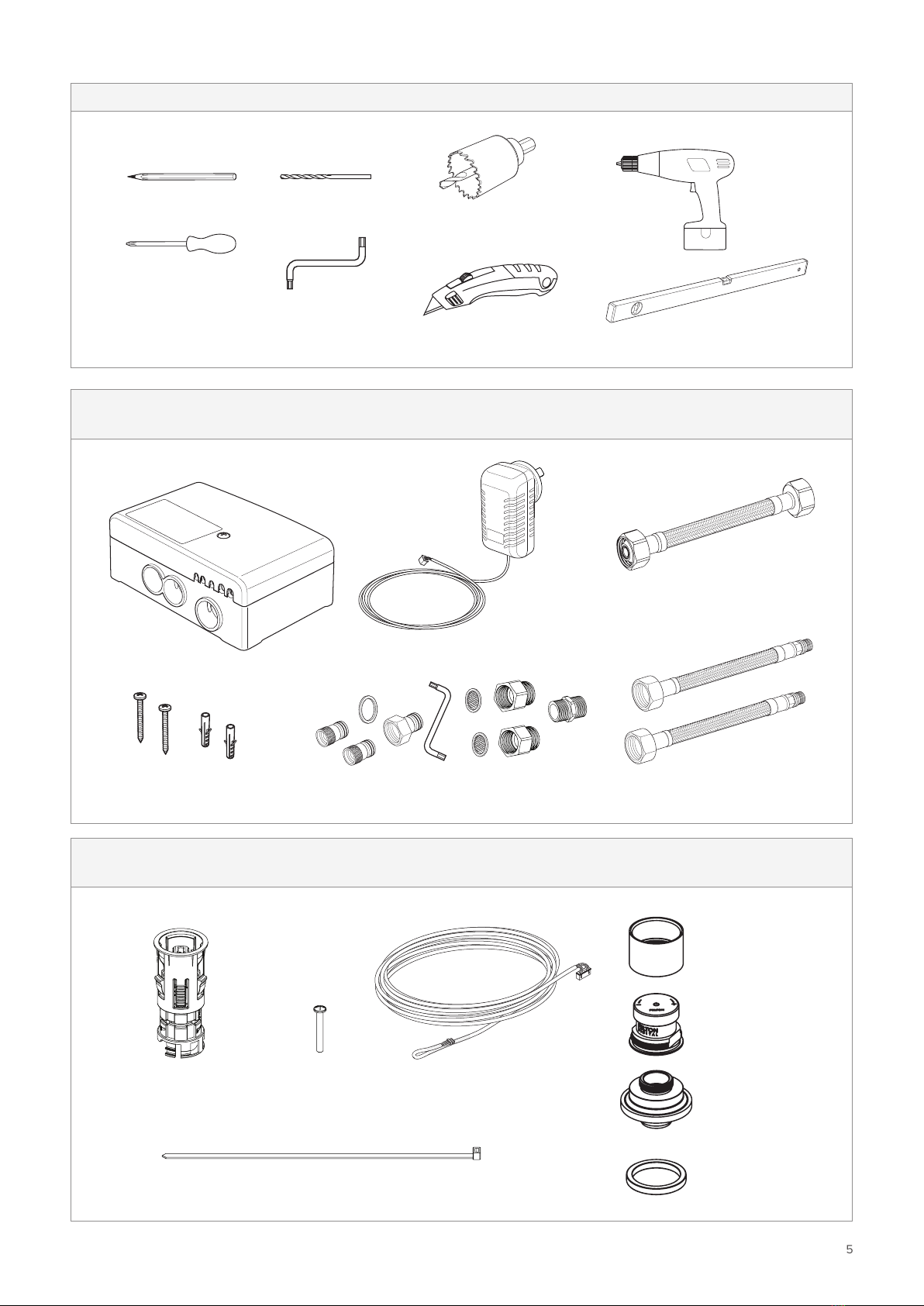
BOX 1
DIGITAL MIXER
TOOLS REQUIRED
7. Drill
4. Torx screwdriver
(included in box 1)
3. Phillips screwdriver
2. Drill bit ø5mm
1. Pencil
8. Spirit level
6. Utility knife
1. Temperature Control Unit
4. Set of Screws: 2x 5x50mm
2. 12V AC Adapter (Cable length: 1m)
BOX 2
CONTROL UNIT
1. Control Mounting Tube
4. Cable Tie
5. Control Sleeve
8. Foam Seal
6. Control Wheel
7. Control Housing
2. Screw 3. Control Data Cable 10m
5. ø30-32mm hole saw
5. Adapter set 6. 2x Inlet hoses (supplied)
3. F-F Outlet Hose

6
FELTON
BOX 3B
DECK MOUNTED SPOUT
BOX 3A
DECK MOUNTED SPOUT
1. Spout
1. Extension Tube 2. 1 x 2mm allen key
4. Key for flow regulators
Top
View
Side
View
3. 3 x Aerators/Flow Regulators
(1x is prefitted to the spout)
Install product as supplied.
IF YOU ARE INSTALLING AS A BASIN / SINK MIXER
IF YOU ARE INSTALLING AS A BATH MIXER
Remove flow regulator from the spout and replace with a flow straightener (full flow).
FLOW REGULATORS
Pink Flow Regulator 4l/min
Blue Flow Regulator 6l/min (factory fitted)
White Flow Regulator 8l/min
There additional flow regulators supplied in
the box. Once the product is installed and has
been checked for leaks, you can test the
dierent flow regulators to see which one is
the best option for your situation.
7
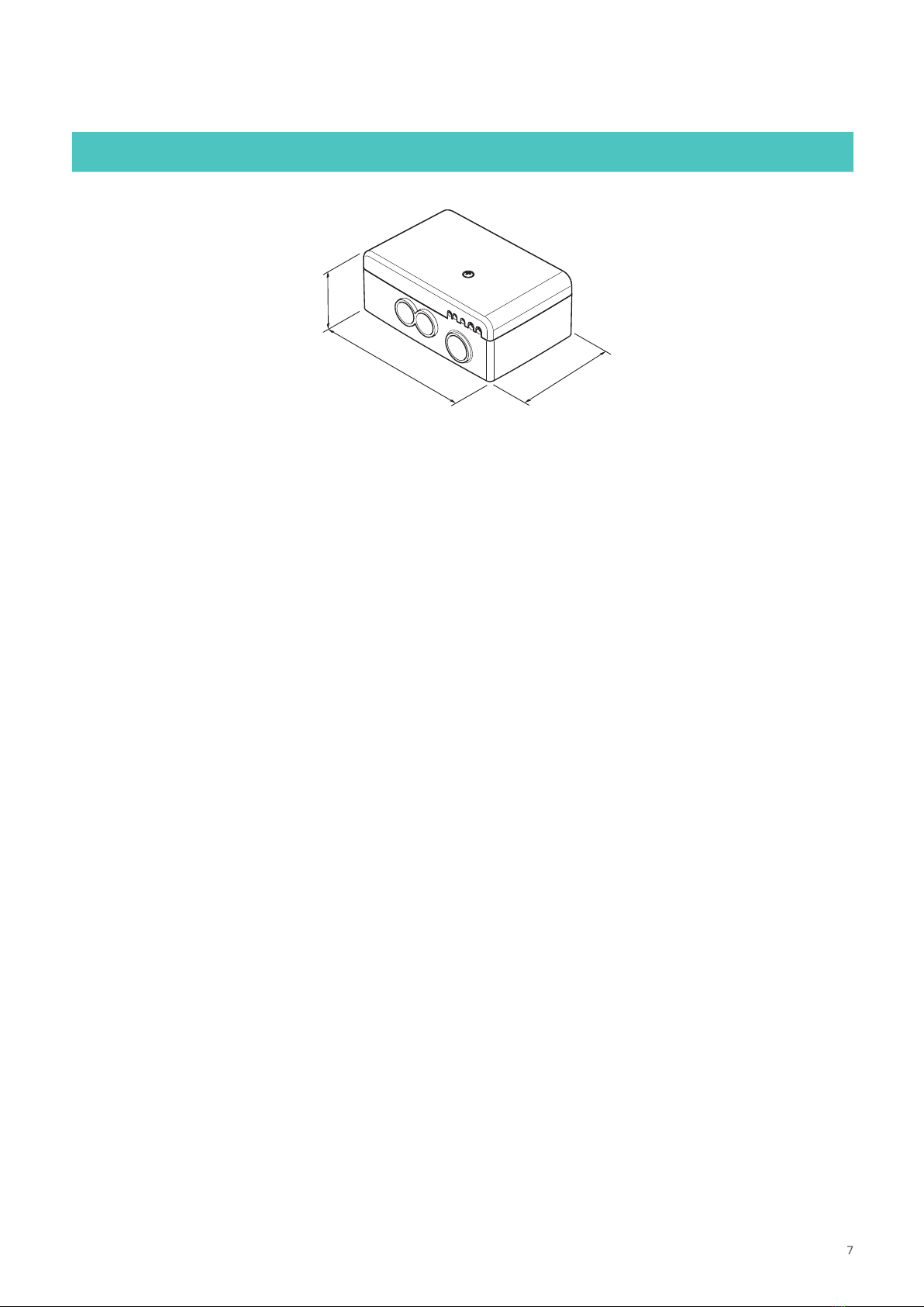
TATE DIGITAL DECK MOUNTED MIXER INSTALLATION GUIDE
MEASUREMENTS
78mm
115mm
45mm

8
FELTON
SCOPE OF APPLICATION
Under Sink (Recommended)
Warning: Please ensure that all electrical
installations are installed by a registered
electrician and complies with the Electrical
(Safety) Regulations of NZ.
Important: The Digital Mixer must have an
access panel.
Important: The Digital Mixer must
be accessible and should not be
sealed in the wall
Wire and Data Cable
must be installed prior
to the wall lining.
It is recommended
that the Data Cable is
installed in conduit for
ease of maintenance.
Control Unit
Hot in
Cold in
Digital Mixer
Spout Outlet
Cable length
10m max.
Power supply
must be within
1m from the
digital mixer
Control cable
Pipework in
Pipework out
Power supply
9
TATE DIGITAL DECK MOUNTED MIXER INSTALLATION GUIDE
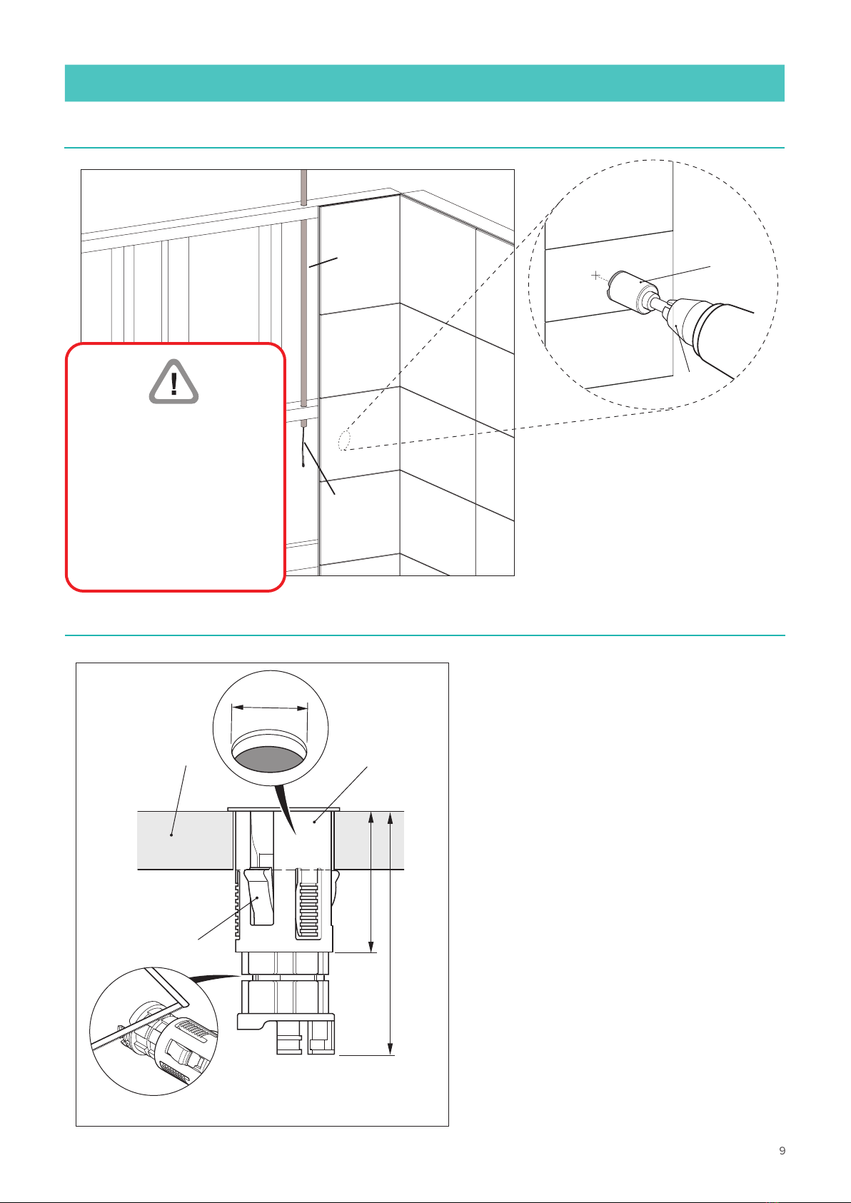
1
CONTROL UNIT INSTALLATION
2
Fig. 2
Tightening lugs
Cutting slot
75mm
Min.
55mm
Bench Mounting tube
ø30-32mm
Please note: The Data Cable is
10 metres in length and therefore
the Control Unit and Digital Unit
need to be positioned accordingly
within this distance. It is recommen-
ded that the Data Cable is installed
in conduit for ease of maintenance.
The Control Tube can be reduced in
length if required by cutting along
the cutting slot (see Fig. 2).
Prepare a Ø30-32mm hole
in the finished wall, deck or
counter/vanity. Position the
drill/hole saw where the
Control Unit is to be located.
Conduit
Data Cable
Cut Position
Drill
Hole
saw
Data Cable must be
installed prior to the
wall lining.
It is recommended
that the Data Cable is
installed in conduit for
ease of maintenance.
*This Control Unit can also be installed as a Wall Mounted unit or a Deck Mounted unit
10
FELTON
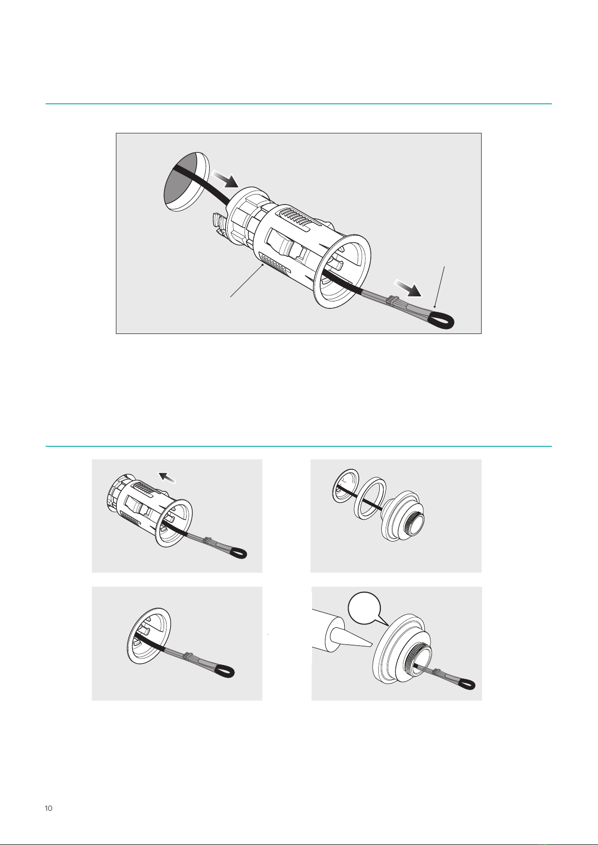
3
4
Using the Data Cable, thread the end with the small connector through the hole and Control
Mounting Tube. This end of the cable is protected with a plastic sleeve, leave this on until later
in the installation.
Control Mounting Tube
Data Cable
Push the Control Mounting
Tube into the hole until the
front flange sits against the
wall.
Apply a silicone bead on the
back of the Control Housing,
then push the Control Housing
into the Plastic Tube until it is
firmly fitted on the unit.
Foam Seal
Control Housing
CLICK
11
TATE DIGITAL DECK MOUNTED MIXER INSTALLATION GUIDE
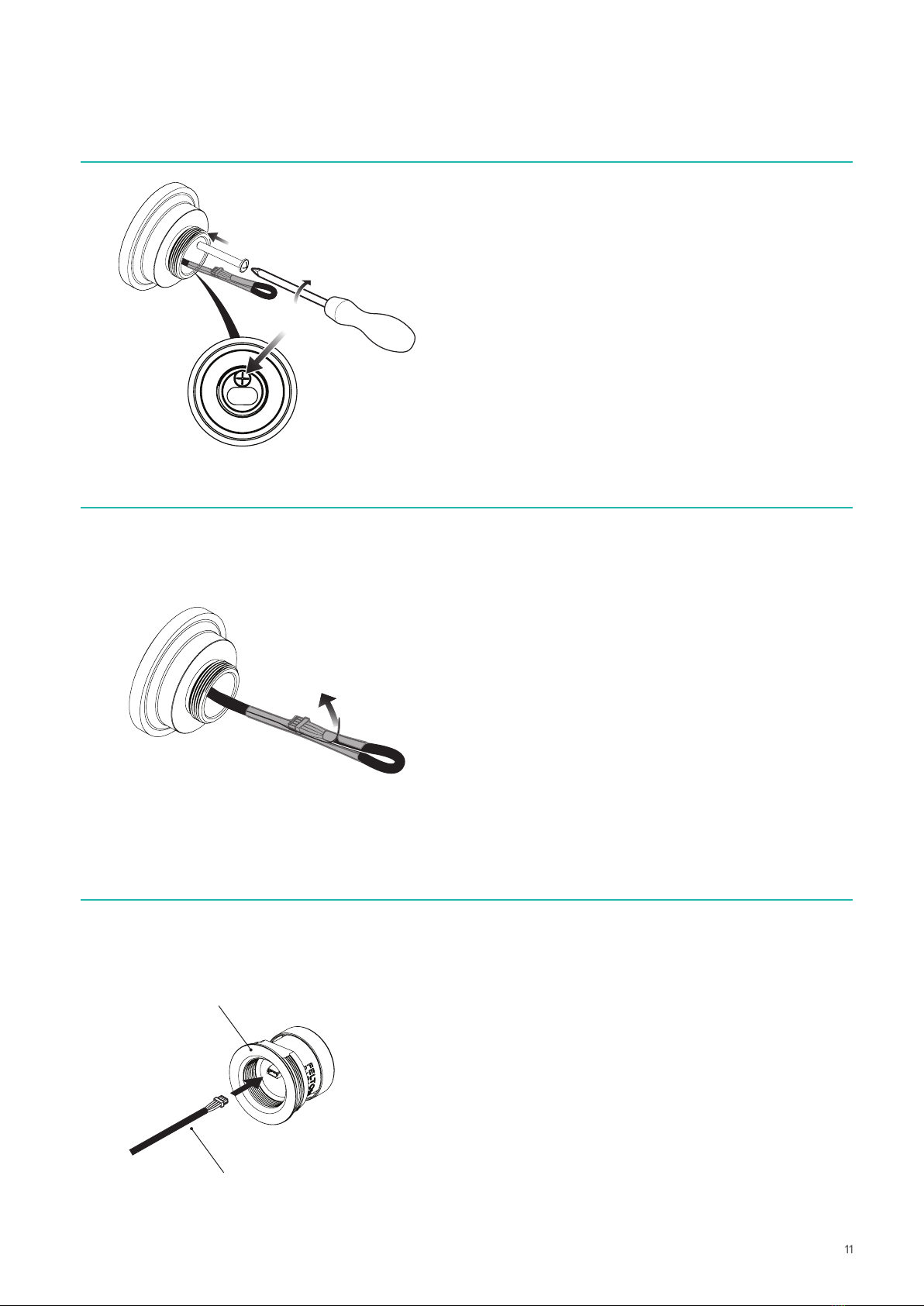
5
Tighten the screw inside the
Control Housing and ensure the
screw is aligned with the Plastic
Mounting Tube.
This tightens the lugs on the
inside of the wall. Tighten until
there is no rotation of the
Control Housing.
6
7
Pull the red strip to release
the connector from the plastic
sleeve.
Push the four pin connector
into the socket on the back of
the Control Wheel.
Control Wheel
Data Cable

12
FELTON
8
Thread in the cable and fit the Control Wheel onto the Housing.
Fit the Control Sleeve onto the Control Wheel.
Ensure that you fit the Control Sleeve in the correct orientation.
SIDE VIEW
13
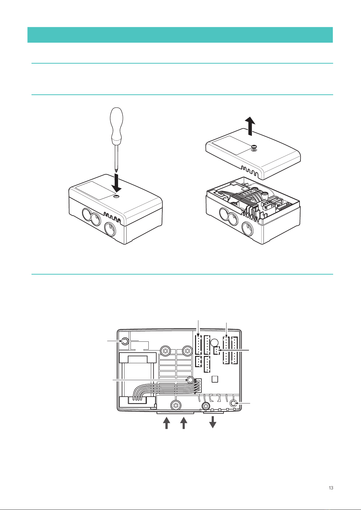
TATE DIGITAL DECK MOUNTED MIXER INSTALLATION GUIDE
3Inside the Temperature Control Unit
DIGITAL MIXER INSTALLATION
Outlet
Hot Cold
Inlets
Fixing holes
Fixing hole
Cover retaining
holes
Transformer 12V /
Wall plug
Control unit
1Ensure that all pipes will reach your mixer mounting location - see page 6 for details
2Remove the cover
14
FELTON
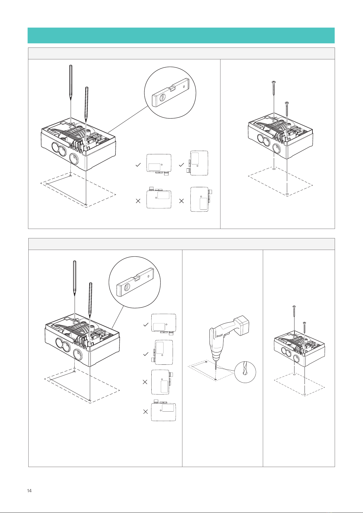
MOUNTING OPTIONS
MOUNTING FOR NOG
2Install the Digital Mixer
99mm
1Mark fixing holes
56mm
If installed vertically, use orientation
shown
*
MOUNTING FOR CONCRETE
2Drill fixing holes
99mm
56mm
ø5mm
3Install the
Digital Mixer
99mm
1Mark fixing holes
56mm
If installed
vertically, use
orientation
shown
*
15
TATE DIGITAL DECK MOUNTED MIXER INSTALLATION GUIDE
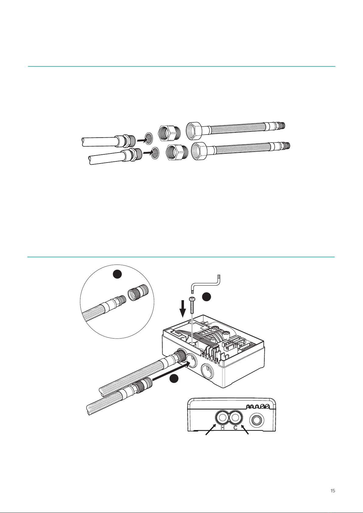
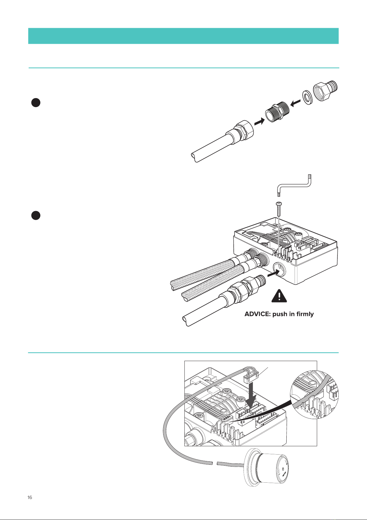
4. Connect the two Inlet hoses with the MF adaptors and filters to the water supply feed
5.
Large retaining bolt
A- Connect the brass adaptors into the flexi hoses.
B- Fit both flexi hoses (with the brass adaptor on) firmly into the unit box.
C- Fit the large retaining bolt with a torx screw driver supplied.
A
B
C
Hot water supply
Cold water supply
Hot inlet Cold inlet
16
FELTON
7
Connect the Data Cable coming
from the Control Unit. Use the
large 6 pin connector and push
firmly into the socket. Feed the
cable through the one of the
guide slots in the front of the
Digital Mixer.
Data Cable
connection
DIGITAL MIXER INSTALLATION
AFit the outlet pipe on to the brass connectors
BPush the outlet fitting into the Digital Mixer
and fit a small retaining bolt with torx screw
driver supplied
Outlet pipe
Short retaining bolt
6

17
TATE DIGITAL DECK MOUNTED MIXER INSTALLATION GUIDE
Fit the cover back on to the base. Using a Phillips screwdriver secure the cover in position.
The unit is now ready for commissioning. Please see User Guide.
IMPORTANT: Electrical supply
must be installed by a qualified
electrician (if required).
Please Note: Leave the torx taped to the box for future use
9
IMPORTANT: Fit cables into slots to allow cover to properly close at end of installation
8
Connect the power cable coming from the transformer. Use the connector and push firmly into
the socket. Feed the cable through the guide slot in the front of the Digital Mixer.
Power cable
connection
18
FELTON
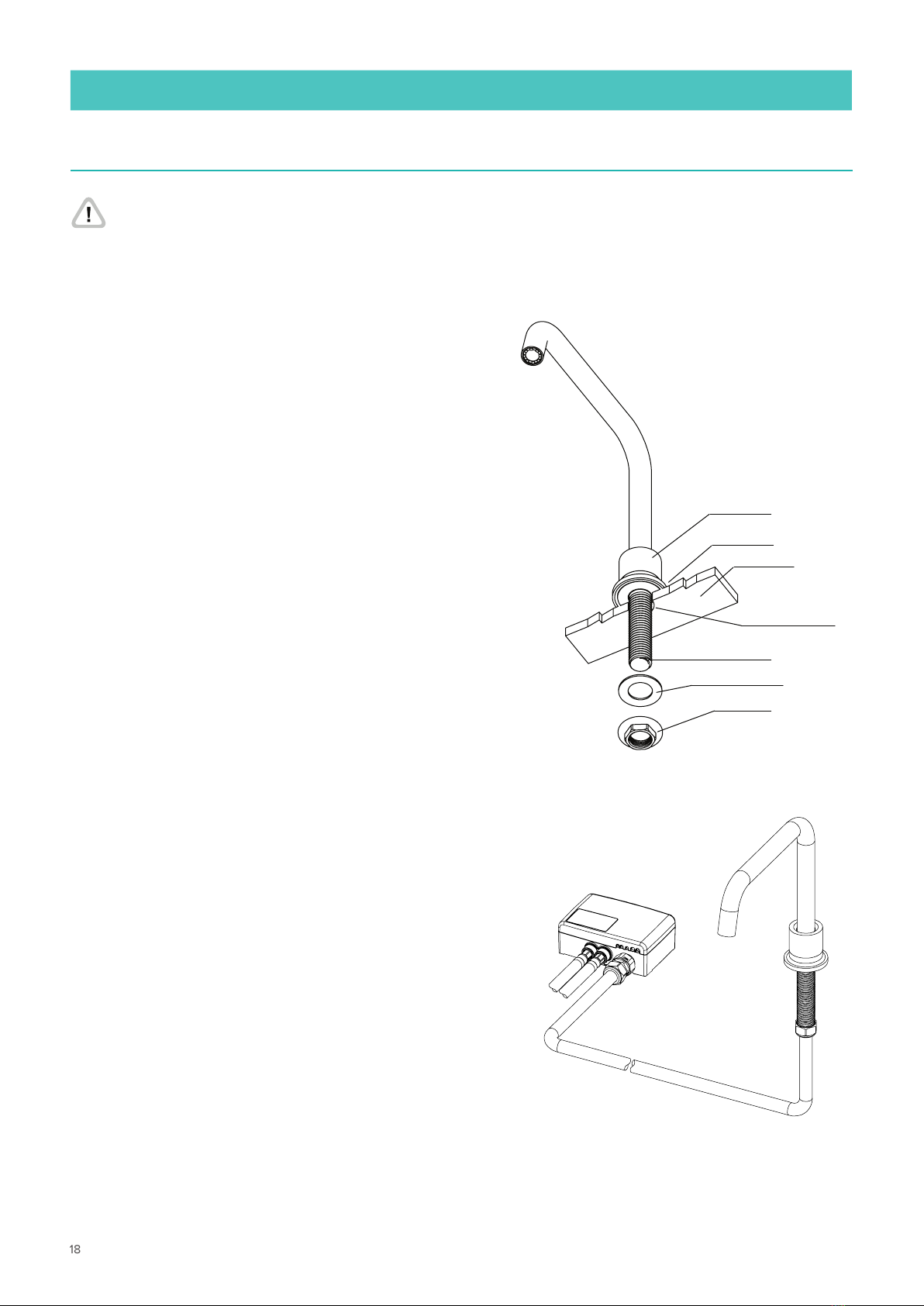
DECK MOUNTED SPOUT INSTALLATION
1
Cut 1x mounting hole 25mm in diameter in
bench top or vanity - approximately 45mm
from the edge of the basin.
Fitting the spout:
1. Ensure the o-ring is fitted to the base
of the spout.
2. Remove the lock nut, rubber washer and
lower into the spout hole.
3. From UNDERNEATH the bench, secure
with the rubber washer and lock nut.
4. Connect spout to digital mixer box using the
F-F hose or your own supplied (see Fig. 1).
Spout Unit
Bench Top
Cut a mounting
hole 25mm
1/2“BSP
Rubber Washer
Lock Nut
Silicone seal
If mixer is being installed on a vitreous china bench top, apply silicone sealant to
the base ring to ensure a water-tight seal on the uneven surface.
Fig. 1
19
TATE DIGITAL DECK MOUNTED MIXER INSTALLATION GUIDE
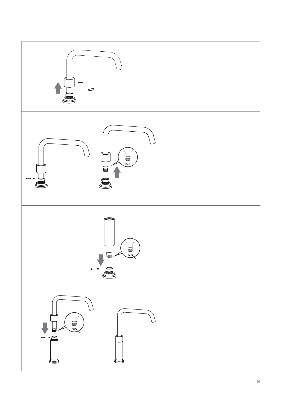
CONVERTING THE SPOUT FROM STANDARD TO TALL (OPTIONAL)
1. Loosen the cover sleeve by
unwinding from the base.
2A. Using the 2mm Allen Key
supplied, undo the grub screw.
2B. Remove the spout from the
base, ensuring that the white
washer stays in place.
3A. Take the Extension Tube and
fit into the base, ensuring the
grub screw aligns with the hole
and push on firmly.
3B. Tighten the grub screw.
4A. Loosen the grub screw on the
Extension Tube and connect the
spout, ensuring the grub screw
aligns with the hole and push on
firmly. Tighten the grub screw.
4B. Secure the cover sleeve to the
Extension Tube by winding it down.
2A.
2B.
4A. 4B.
COVER
SLEEVE
Plastic
Washer
Plastic
Washer
3A.
3B. Plastic
Washer

20
FELTON
1Ensure that the Digital Mixer is installed correctly installed according to the instructions above.
Turn on the water supply and check the unit and plumbing for leaks. Once the plumbing is confirmed to
be water-tight, connect the power supply and conduct the operational test below.
2 Open
Push the Smartflow Interface once.
The Digital Mixer opens and the
LED illuminates.
3 Close
Push the Smartflow Interface again.
The Digital Mixer closes and the
LED goes o.
OPERATIONAL TEST
DECK MOUNTED
SHOWER / WALL MOUNTED
DECK MOUNTED
SHOWER / WALL MOUNTED
Other manuals for TATE
3
Table of contents


