Fema Electronica ASGARD CCT-01 User manual
2.- ADJUST AND CALIBRATION PROCEDURE
1.- Open the housing to access the instrument internal circuits
2.- Select apropriate jumpers on boards ME, MP and MS
3.- Connectsignalgeneratortosignalinputterminals
Connect multimeter to signal output terminals
4.- Power up the instrument as indicated on the label
5.- Generatethesignallevellow
Operatepotentiometer P1 onME until indicationshows desired signaloutput low level
6.- Generatethesignallevelhigh
Operate potentiometer P2 on ME until indication shows desired signal output low level
7.- Repeat steps 6 to 9 in order to correct deviations and check adjust
8.- On model CCT-32, check excitation output voltage for transducers, 24 Vdc, maximum 25 mA
Weight 270gr.
WireCrossection 4 mm2maximum
HousingandCover IP-40
Terminals IP-20
HousingandCover Polycarbonate, Light Grey, RAL 7032, UL 94 V-1
Terminals Polycarbonate,Dark Grey, UL94 V-2
Mounting StandardDINrail(DIN46277,DINEN50022)
(35 x 7,5mm) (1,38 x 0,3") .
1.- COMMON TECHNICAL SPECIFICATIONS
Output 0/20mA ó 4/20mA RL< 600 Ohms max. 22 mA ±3%
Output 0/10 Vdc RL> 1000 Ohms max. 11 V ±3%
ResponseTime ≤250 mSec
GalvanicIsolation 2 KVeff. 50 Hz/1 min (between all circuits)
IsolationTest 4 KVeff. 50 Hz/1min
Accuracy Class < 0,2forCCT-32andCCT-01
Class < 0,3forCCT-04andCCT-08
Ripple ≤0,5 %
Pass Band 1,5 Hz (-3 dB)
StorageTemperature -30 to +80 °C (-22 to +176 ºF)
WorkingTemperature -10 to +60 °C (+14 to +140 ºF)
TemperatureCoef. ≤0,015 %/ °C
PowerSupply See labeloninstrument
Consumption <1,5 VA
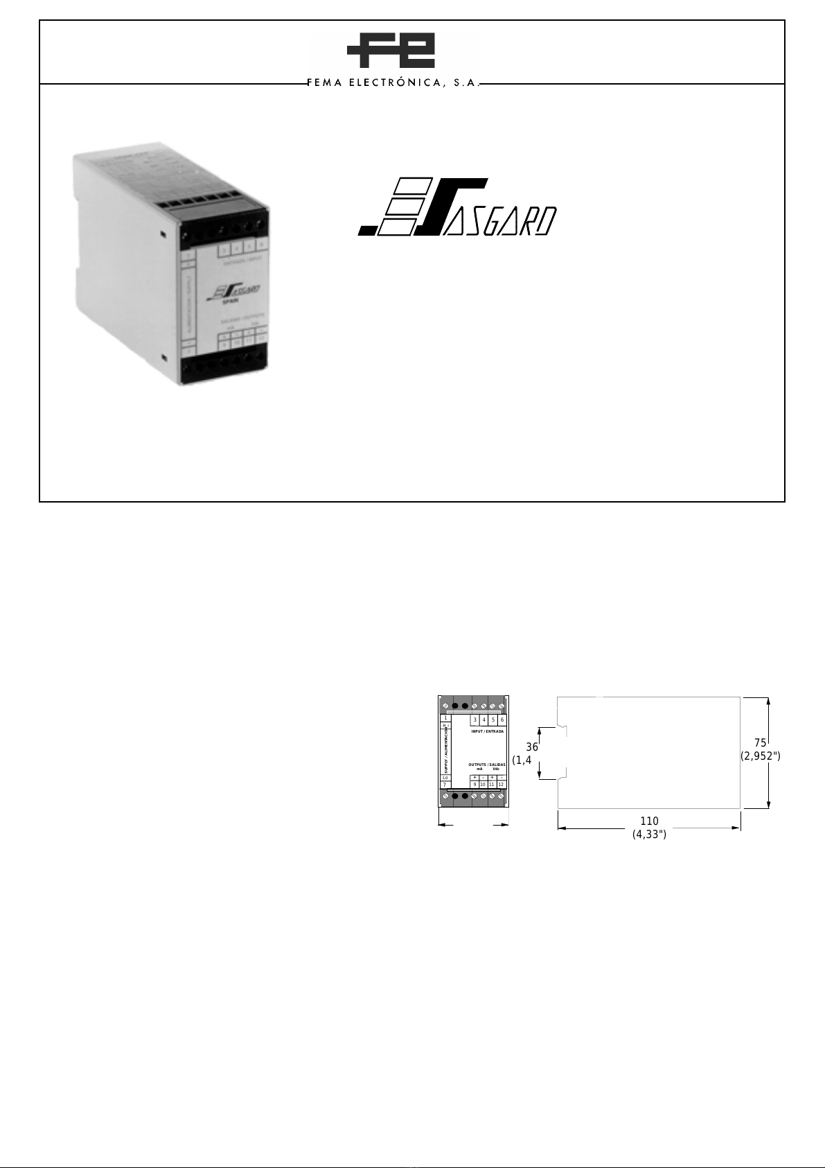
MECHANICALDIMENSIONSinmm(inches)
45
(1,771")
OUTPUTS / SALIDAS
mA Vdc
INPUT / ENTRADA
SUPPLY / ALIMENTACION
3 4 5 6
9 10 11 12
7
1
+
Lo
H i
+--
75
(2,952")
110
(4,33")
36
(1,417")
CONVERTER-TRANSMITER .- Serie CCT
CCT- 01 .- Signals in DC Voltage (Vdc)
CCT- 04 .- Signals in AC Current (Aac)
CCT- 08 .- Signals in AC Voltage
CCT- 32 .- Signals in Process (mAdc)
13/96 rev.0911/03
P.I. Santiga Altimira 14 (Talleres 14, Nave 2) E08210-BARBERÀ DELVALLÈS(SPAIN)
6.- INPUT SIGNAL MODULE
TheMEmoduletogetherwithMPmodule,allowconfigurationofdifferentinputsignalranges,andcalibratetheinstrument.On
theME are located the potentiometers and jumpers for Zero and Gainadjustment.OnMPmodulesarelocatedthejumpers
forsignalinputconfiguration.
Jumper1.-ClosedforGross PositiveOffset
Jumper2.-ClosedforGrossNegativeOffset
JumperA.-ClosedforFineNegativeOffset
JumperB.-ClosedforMaximum GAIN
JumperC.-ClosedforMiddleGAIN
Jumper B y C .- Open for Minimum GAIN
Note : jumpers 1,2,A,B and C normally OPEN
P1 .- ZeroAdjustPotentiometer
P2 .- GainAdjustPotentiometer
OnSolderSide
1
2P2
P1
ABC
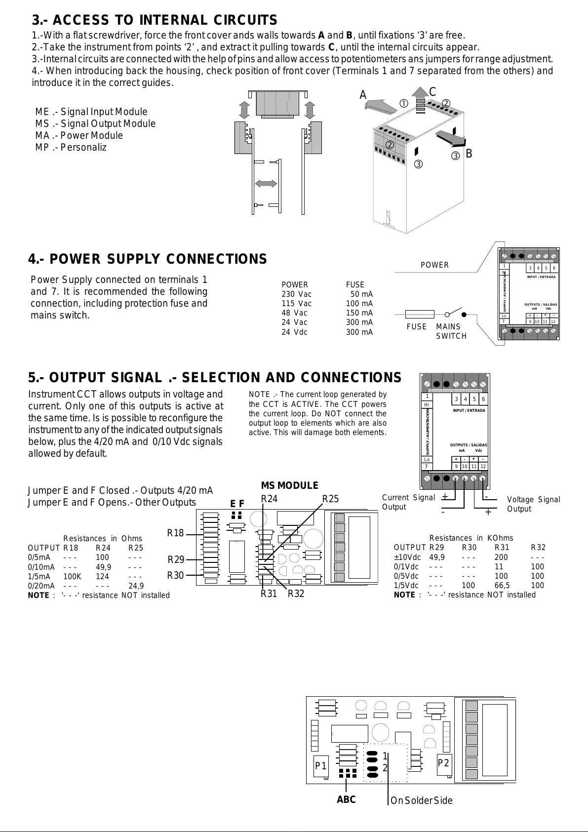
Power Supply connected on terminals 1
and 7. It is recommended the following
connection, including protection fuse and
mains switch.
POWER FUSE
230 Vac 50 mA
115 Vac 100 mA
48 Vac 150 mA
24 Vac 300 mA
24 Vdc 300 mA
4.- POWER SUPPLY CONNECTIONS POWER
FUSE
OUTPUTS / SALIDAS
mA Vdc
INPUT / ENTRADA
SUPPLY / ALIMENTACION
3 4 5 6
9 10 11 12
7
1
+
Lo
Hi
+
--
MAINS
SWITCH
NOTE .- The current loop generated by
the CCT is ACTIVE. The CCT powers
the current loop. Do NOT connect the
output loop to elements which are also
active. This will damage both elements.
5.- OUTPUT SIGNAL .- SELECTION AND CONNECTIONS
InstrumentCCT allows outputsin voltage and
current. Only one of this outputs is active at
thesametime.Isis possible to reconfigurethe
instrumenttoanyoftheindicatedoutputsignals
below,plus the 4/20mA and 0/10 Vdcsignals
allowedbydefault.
Resistances in Ohms
OUTPUT R18 R24 R25
0/5mA - - - 100 - - -
0/10mA - - - 49,9 - - -
1/5mA 100K 124 - - -
0/20mA - - - - - - 24,9
NOTE : ‘- - -‘ resistance NOT installed
Resistances in KOhms
OUTPUT R29 R30 R31 R32
±10Vdc 49,9 - - - 200 - - -
0/1Vdc - - - - - - 11 100
0/5Vdc - - - - - - 100 100
1/5Vdc - - - 100 66,5 100
NOTE : ‘- - -‘ resistance NOT installed
MSMODULE
Jumper E and F Closed .- Outputs 4/20 mA
JumperE and F Opens.- OtherOutputs
OUTPUTS / SALIDAS
mA Vdc
INPUT / ENTRADA
SUPPLY / ALIMENTACION
3 4 5 6
9 10 11 12
7
1
+
Lo
Hi
+
--
Voltage Signal
Output
Current Signal
Output +-
+-
R29
R30
E F R24 R25
R31 R32
R18
C
A
B
3.- ACCESS TO INTERNAL CIRCUITS
1.-Witha flat screwdriver, force the front cover ands wallstowards Aand B, untilfixations ‘3’ are free.
2.-Take the instrument from points ‘2’ ‚ and extract it pulling towards C, until the internal circuits appear.
3.-Internalcircuitsareconnectedwiththehelpofpinsandallowaccesstopotentiometersansjumpersforrangeadjustment.
4.- When introducing back the housing, check position of front cover (Terminals 1 and 7 separated from the others) and
introduce it in the correct guides.
ME .- Signal Input Module
MS .- Signal Output Module
MA.- PowerModule
MP .- Personalizer Module
ME MS
MA
MP

10.- PERSONALIZER MÓDULES .- JUMPERS
JUMPER-1
Soldadura
R8
Shunt D C B A
RShunt
R8
PersonalizerModule
MP-04
D C B A
PersonalizerModule
MP-01 Y MP-08 PersonalizerModule
MP-32
D - - A
9.- MODEL 32 .- RANGES, JUMPERS, CONNECTIONS
TheCCT convertercanbeconfiguredinorder to adequateinputandoutputsignalranges to thefinalapplication.We
showherundertechnicalinformationonthemostcommonranges.
RANGE 0/50mAdc 0/5mAdc 0/20mAdc 4/20mAdc
JumpersMPClosed D A, D D D
JumpersMEClosed None None C A, C
MinimumInputSpan 5 mAdc 0.5 mAdc
InputImpedance 20Ohms 20Ohms
Overload 100mAdc 100mAdc
Terminal 3 = +24 Vdc
Terminal 5 = Signal
Terminal 6= Common
Terminals.-Dependingonthesignalgeneratortype.For2WireTransducersandcurrentgeneratorssee
connections.3 Wire Transducers, connect terminals 3 (24Vdc), 5 (Signals) and 6(Common).
Note .- The CCT offers the excitation voltage (24 VDC @50mA) for passive transducers with 2 and 3
wires,onTerminal3.
Minimum Input Span.- Minimum range at input in order to have a maximum output range in 0/10 Vdc
or 4/20 mA.
Current
Generator
OUTPUTS / SALIDAS
mA Vdc
INPUT / ENTRADA
SUPPLY / ALIMENTACION
3 4 5 6
9 10 11 12
7
1
+
Lo
Hi
+
--
+-
2 Wire
Transducers
+
-
7.- MODELS 01 and 08 .- RANGES, JUMPERS, CONNECTIONS
TheCCT converter canbeconfiguredinordertoadequateinput and output signalrangestothefinalapplication.We show
herundertechnicalinformationonthemostcommonranges.
RANGE 0/100 mV 0/1 V 0/10 V 0/100 V 0/650 V
JumpersMPClosed A None None D B
JumpersMEClosed None None None None None
TerminalsConnection 5 and 6 5 and 6 4 and 6 4 and 6 4 and 6
MinimumInputSpan 10 mV 0.1 V 1 V 10 V 100 V
InputImpedance 100KOhms 100KOhms 1 MEGA Ohm
Overload 25 V 75 V 1000 Vdc and 750 Vac
Minimum Input Span.- Minimum range at input in order to have a maximum output range in 0/10 Vdc
or 4/20 mA.
OUTPUTS / SALIDAS
mA Vdc
INPUT / ENTRADA
SUPPLY / ALIMENTACION
3 4 5 6
9 10 11 12
7
1
+
Lo
Hi
+--
>1V
+
-<1V
+
-
CCT-01
CCT-08
OUTPUTS / SALIDAS
mA Vdc
INPUT / ENTRADA
SUPPLY / ALIMENTACION
3 4 5 6
9 10 11 12
7
1
+
Lo
Hi
+
--
8.- MODEL 04 .- RANGES, JUMPERS, CONNECTIONS
TheCCT converter canbeconfiguredinordertoadequateinput and output signalrangestothefinalapplication.We show
herundertechnicalinformationonthemostcommonranges.
RANGE 0/5 Aac 0/1 Aac 0/500mAac 0/50 mAac 0/5 mAac
JumpersMPClosed A, 1 A, 1 A, 1 D A y D
JumpersMEClosed None None None None None
RShunt 0.02Ohm* 0.1Ohm* 0.2Ohm* 20Ohm(R8) 20Ohm(R8)
TerminalsConnection 5 and 6 5 and 6 5 and 6 5 and 6 5 and 6
MinimumInputSpan 500mAac 100 mAac 50 mAac 5 mAac 0.05 mAac
InputImpedance 0.02Ohms 20 KOhms
Overload 7,5 Aac 100mAac
* Resistances of 3W
** R8 is installed and should not be removed when using different ranges.
Minimum Input Span.- Minimum range at input in order to have a maximum output range in 0/10 Vdc
or 4/20 mA.
Aac, mAac
CCT-04
Manufacturer: FEMA ELECTRÓNICA, S.A.
Address: Centro Industrial Santiga
c\ Altimira, 14 (Talleres 14 - Nave 2)
E-08210 - Barberà del Vallès (ESPAÑA)
Products Covered .- SERIES: CCT MODELS : 01, 04, 08 and 32
We declare that the above referrenced instruments comply with the valid rules and regulations detailed below :
IMMUNITY: EN 50082-1 (1992)
CEI 801-2: UNE 20801-2-94 (Nivel 2)
CEI 801-3: UNE 20801-3-94 (Nivel 3)
CEI 801-4: UNE 20801-4-94 (Nivel 3)
EMISSION: UNE 50081-1 (1992)
EN55022:ClaseB/CISPR22
EN 60204-1 and prEN 60204-1 CHAP. 12, 13Electrical security
prescriptions.
UNE21352-76:CEI359-71Operatingqualityexpressionsforelectronic
equipments.
UNE 20652-80: CEI 284-68Behaviour rules inherent to the handling
of electronic equipments and other similar technics.
REGULATIONS:
EUROPEANDIRECTIVEFORLOWVOLTAGED73/23/CEEAMENDED
BY D93/68/CEE. Equipments powered from 50 to 1000 Vac. and /or from
75 to 1500 Vdc.
EUROPEANDIRECTIVEFOR THE SAFETYD92/59/CEE.
ELECTROTECHNICALREGULATIONFORLOWVOLTAGE (RBT) ITC
21, ITC 29, ITC 35. Equipments with power supply lower than 50 Vac
and/or 75 Vdc.
EUROPEANDIRECTIVEFOR ELECTROMAGNETIC COMPATIBILITY
D89/336/CEE AMENDED BY D93/68/CEE, ACCORDING TO RD1950/
1995 (01/12). Francisco Guàrdia
Quality Manager
Barberà del Vallès, 1998
DECLARATION OF CONFORMITY
INCLUDE THE FOLLOWING INFORMATION.-
Serial Number : ______________________________
Signal Input / Signal Output:____________________
Power Supply : ________________________
Provided by: ____________________________
Description of defective encountered :
13.- WARRANTY
FEMA ELECTRÓNICA, S.A. warrants this product free of defects in workmanship for ONE (1) year from the date of shipment. This Warranty
is VOID if the unit shows evidence of damages as a result of misapplication, accident, misuse or if the product had been tampered or repaired
by personnel or companies without the official authorization of FEMA ELECTRÓNICA, S.A. This Warranty is VOID also for damages caused by
defective or inappropriate applications. In case of malfunction return the unit to the manufacturer for evaluation. Within the warranty period, and
after examination, and if the unit is found to be deffective and covered by this warranty, the unit will be repaired or replaced.
LIMITATION OF LIABILITY : FEMA ELECTRÓNICA, S.A. shall not be responsible for any damage or loss to other equipment however caused,
which may be experienced as a result of the installation or use of this product. The liability shall not exceed the purchase price paid of the product
upon which liability is based. In no event shall FEMA ELECTRÓNICA, S.A. be liable for consequential, incidental or special damages.
SHIPMENTS FOR REPAIR.- Send free of charges and apropriately packed, to the following address :
FEMAELECTRÓNICA,S.A.
REPAIRS
Pol.Ind.Santiga (Altimira 14, Talleres 14, Nave 2)
Apartado de Correos 49
E-08210 BARBERÀ DEL VALLÈS (ESPAÑA)
11.- PRELIMINARY NOTES
INSTALLATION.-PRECAUTIONS
Theinstallationanduse of this unit must be done byqualified
personnel. The unit has not AC (mains) switch, neither
internal protection fuse. it will be in operation as soon as
poweris connected.Theinstallation mustincorporateanexternalmains switch
with a protection fuse in the power line
Power : 230 Vac Fuse 50 mA
Power : 115 Vac Fuse 100 mA
Power : 24 Vdc Fuse 300 mA
Add the appropriate devices to the installation in order to protect the operator
and system when using the unit to control a machine or process where injury
to personnel or damage to equipment may occur as a result of failure of the
unit. SAFETY PRESCRIPTIONS.- This unit has been designed and
tested under EN-61010-1 rules and is delivered in good condition.
This operator's manual contains useful information for electrical
connections. Do not make wiring signal changes or connections
when power is applied to the unit. Make signal connections before
power is applied and, is reconnection is required, disconnect the AC (mains)
power before such wiring is attempted. Install the unit in a places with a good
ventilation to avoid the excessive heating. And far from electrical noise
source or magnetic field generators such as power relays, electrical motors,
speed controls etc... The unit cannot be installed in open places. Do not use
until the installation is finished.
POWER SUPPLY.- The power supply must be connected to the adequate
terminals (see the connection instructions). The characteristics of the power
supplyare showedontheside label.Pleasemakesure thattheunit is correctly
connected to a power supply of the correct voltage and frequency. Do not
use other power supply otherwise permanent damage may be caused to the
unit. Do not connect the unit to power sources heavily loaded or to circuits
whichpower loads in cycleON-OFForto circuits whichpowerinductiveloads.
WARNING.- If the power supply is dc voltage, be careful with the polarity
indicated for each terminal.
EXCITATION VOLTAGE.- The model CCT-32 supply the Excitation voltage for
sensors, through the terminals 3 & 5. Do not connect these terminals to other
external power supply, permanent damages may result to the unit.
SIGNAL WIRING.- Certain considerations must be given when install the signal
input wires. If the wires are longs can act like an antenna and introduce the
electrical noise to the unit, therefore: Do not install the signal input wires in the
same conduit with power lines, heaters, solenoids, SCR controls etc...and
always far from these elements. When shielded wires are used, leave
unconnected the shield on the transmitter side and connect the other end of the
shield to the ground terminal of the machine.
SAFETYCONSIDERATIONS
PRESCRIPTIONS.- Before starting any operation of adjustment, replace-
ment, maintenance or repair, the unit must be disconnected from any kind of
powersupply. Keep theunitclean , toassure goodfunctioning and performance.
Toprevent electrical or firehazard,donot expose the unittoexcessivemoisture.
Do not operate the unit in the presence of flammable gases
or fumes, such an environment constitutes a definite safety
hazard.Theunit is designed tobemountedina metal panel.
If the unit shows signs of damage, or is not able to show the
expected measures, or has been stored in a bad conditions
or a protection failure can occur, then do not attempt to operate and keep the
unit out of service.
IN CASE OF FIRE
1.- Disconnect the unit from the power supply.
2.- Give the alarm according to the local rules.
3.- Switch off all the air conditioning devices.
4.- Attack the fire with carbonic snow, do not use water
in any case.
WARNING : In closed areas do not use systems with vaporized liquids.
This manual suits for next models
4


