nextys DCW20 How to use

1
Short Form Installation Manual
Nextys SA. Via Luserte Sud 6, 6572 Quartino – Switzerland
Phone: +41-(0)91 8401446 / 8401448; Fax: +41-(0)91 8401447
Models DCW20 - 960W COMBO DC UPS / DC-DC Converter
File No.:
I.M.DCW20
Rev.:
A01
Use latest device Documentation, Software and Firmware to ensure reliable operation of the system
(downloadable from www.nextys.com)
READ THIS CAREFULLY BEFORE INSTALLATION!
LEGGERE ATTENTAMENTE PRIMA DELL’INSTALLAZIONE!
A LIRE ATTENTIVEMENT AVANT L’INSTALLATION!
Before operating, read this document thoroughly and retain it for
future reference.
Non-respect of these instructions may reduce performances and
safety of the devices and cause danger for people and property.
The products must be installed, operated, serviced and maintained
by qualified personnel in compliance with applicable standards
and regulations.
Don’t open the device, it does not contain replaceable
components, the tripping of the internal fuse (if included) is
caused by an internal failure.
Don’t repair or modify the device, if malfunction or failure should
occur during operation, send unit to the factory for inspection. No
responsibility is assumed by Nextys SA for any consequences
deriving from the use of this material.
Prima dell’installazione, leggere attentamente questo documento
istruzioni e conservarle per future consultazioni.
L’inosservanza delle presenti istruzioni può compromettere le
caratteristiche e la sicurezza dell’apparecchio e causare pericolo per le
persone e le cose.
Il prodotto deve essere installato, utilizzato e riparato da personale
qualificato e nel rispetto delle normative vigenti.
Non aprire il prodotto, esso non contiene componenti sostituibili, il
guasto del fusibile interno (se previsto) è causato da un guasto interno.
Non tentare di riparare o modificare il prodotto, se durante il
funzionamento si verificano guasti o anomalie, inviarlo al produttore per
il controllo.
Nextys SA non si assume nessuna responsabilità per qualunque
conseguenza derivante dall’uso di questo materiale.
Lire ces instructions avant l'installation, conserver ce manuel pour
référence future.
Défaut de se conformer à ces instructions peut affecter les
caractéristiques et la sécurité du dispositif, et causer du danger aux
personnes ou aux biens.
Les produits doivent être installés, exploités et entretenus par du
personnel qualifié et en conformité avec les règlements.
N'ouvrez pas le produit, il ne contient aucune pièce réparable, le
déclenchement du fusible interne (le cas échéant) est causé par un
défaut interne. Ne pas essayer de réparer ou modifier le produit ; si
des défaillances se produisent pendant le fonctionnement, retourner
le produit au fabricant pour inspection. Nextys SA n'assume aucune
responsabilité des conséquences éventuelles découlant de
l'utilisation des produits.
CAUTION
ATTENZIONE
AVVERTISSEMENT
RISK OF BURNS, EXPLOSION, FIRE, ELECTRICAL SHOCK, PERSONAL
INJURY.
Never carry out work on live parts! Danger of fatal injury! The
product’s enclosure may be hot, allow time for cooling product
before touching it. Do not allow liquids or foreign objects to enter
into the products.
To avoid sparks, do not connect or disconnect the device before
having previously turned-off input power and wait for internal
capacitors discharge (minimum 1 minute).
RISCHIO USTIONI, ESPLOSIONE, INCENDIO, SCOSSA, LESIONI GRAVI.
Non effettuare mai operazioni sulle parti sotto tensione! Pericolo di
lesioni letali! Il contenitore può scottare, lasciar quindi raffreddare il
dispositivo prima di toccarlo. Non far entrare liquidi o oggetti estranei
nel dispositivo.
Per evitare scintille, non collegare o scollegare l'apparecchiatura prima
di avere tolto tensione di ingresso e prima che sia avvenuta la scarica
dei condensatori interni (min. 1 minuto).
RISQUE DE BRULURES, EXPLOSION, INCENDIE, ELECTROCUTION,
DOMMAGE AUX PERSONNES.
Ne jamais effectuer des opérations sur les parties sous tension!
Danger de mort! Le boîtier peut produire des brûlures, le laisser
refroidir avant de toucher l'appareil. Ne faire pas pénétrer des
liquides ou des corps étrangers dans l'appareil. Pour éviter des
étincelles, ne pas connecter ou déconnecter l'équipement jusqu'à ce
que la tension d'entrée a été supprimée et avant qu'il n'ait eut lieu la
décharge des condensateurs internes (minimum 1 minute).
INTENDED USE
USO PREVISTO
UTILISATION
These are isolated devices suitable for SELV and PELV circuitry and
are designed to be mounted on DIN rail and installed inside a
protective enclosure. They are intended for general use such as in
industrial control, communication, and instrumentation
equipment.
Don’t use these devices in applications where malfunction may
cause injury or death.
I dispositivi sono isolati, adatti per applicazioni SELV e PELV, sono dotati
di aggancio per il montaggio su guida DIN all’interno di quadri elettrici o
contenitori di protezione, per l’utilizzo con controllori industriali, unità
di comunicazione o apparecchi di misura.
Non utilizzare in applicazioni in cui
un eventuale guasto può comportare
rischio di lesioni o di morte.
Les produits sont isolés, appropriés pour les circuits TBTS et TBTP et
sont équipés d'un crochet pour montage sur rail DIN dans des
armoires ou conteneurs de protection, pour utilisation avec les
contrôleurs industriels, des modules de communication ou des unités
de mesure.
Ne pas utiliser ces dispositifs dans une application où un
dysfonctionnement pourrait entraîner le risque des blessures ou de
mort.
ENVIRONMENTAL CHARACTERISTICS
CARATTERISTICHE AMBIENTALI
CARACTÉRISTIQUES ENVIRONMENTALES
Installation in a Pollution Degree 2 environment, Overvoltage
Category I, according to IEC60664-1.
Do not use in wet area or subject to moisture.
Carefully recycle the product and related batteries according to
local regulations.
Usare in ambienti con Grado di Inquinamento 2 e Categoria di
Sovratensione I, secondo IEC60664-1.
Non far funzionare l'apparecchio in un ambiente umido o soggetto a
formazione di condensa. Riciclare il prodotto e le batterie collegate, nel
rispetto delle normative locali vigenti.
Utiliser les produits dans des environnements avec degré de pollution
2, catégorie de surtension I selon IECN60664-1.
Ne pas employer l'appareil dans un environnement humide ou
soumis à la condensation. Recycler les produits et les batteries,
conformément à la réglementation locale..
Declaration of Conformity
NEXTYS SA.
Via Luserte Sud 6, 6572 Quartino - Switzerland
Phone: +41-(0)91 840 14 46 / 840 14 48; Fax: +41-(0)91 840 14 47
E-mail: info@nextys.com
This Declaration of Conformity is suitable to the European Standard EN45014 "General criteria for supplier’s declaration of conformity".
We declare under our sole responsibility that the device included in this box, has passed all processing inspections and the final test and it is in conformity with the product requirements, including all reference
codes and supply specifications.
ROHS compliance: the product respects the EC requirements related to ROHS substances, according to “Restriction of Hazardous Substances” as per document 2011/65/UE
REACH compliance: the product respects the EC requirements related to REACH SVHC directive (EC) 1907/2006
Note: all the reported information comes from our suppliers, NEXTYS SA. has not run any test to evaluate if the specific elements are present.
All indicated devices are designed according to the latest Reference standards, if not expressly indicated through the official documents or files, they have been tested through our internal pre-compliance
testing. Consult directly on www.nextys.com the reference standards applied to each model.
Code Description
DCW20 Combo DC UPS / DC-DC Converter 960W
Certifications and approvals
Reference standards
2014/35/EU (2014) (Low Voltage Directive)
2014/30/EU (2014) (EMC directive)
UL508 (Certified - IND. CONT. EQ. 4WX9 file no. E356563)
EN61010-1 (Safety Standard)
EN61010-2-201 (Safety Standard)
EN61000-6-2 (Generic immunity standard for industrial environments)
EN61000-6-3 (Generic emission standard for residential environments)
2
System Description
DCW20 is a microprocessor controlled unit that can perform 2 functions:
1. UPS rated 960W/20A usable in any system rated 12…48Vdc
2. DC/DC converter (non isolated) rated 960W/20A usable in any combination of IN/OUT voltages 12…48Vdc
For the UPS function you may use 1 battery of 12V, independently of the operating load voltage. For any supply voltages (12…48Vdc) it may use also multiple battery configuration (10…58Vdc).
DCW20 monitors the voltage coming from a DC power supply and in case of power failure a backup battery is supplying the energy to the load. In normal condition the battery is kept charged by
an integrated battery charger supporting various battery chemistries.
As a DC/DC converter (no battery present) the input has to be connected to the battery connector.
The input voltage is converted to any output voltage as per the set-up.
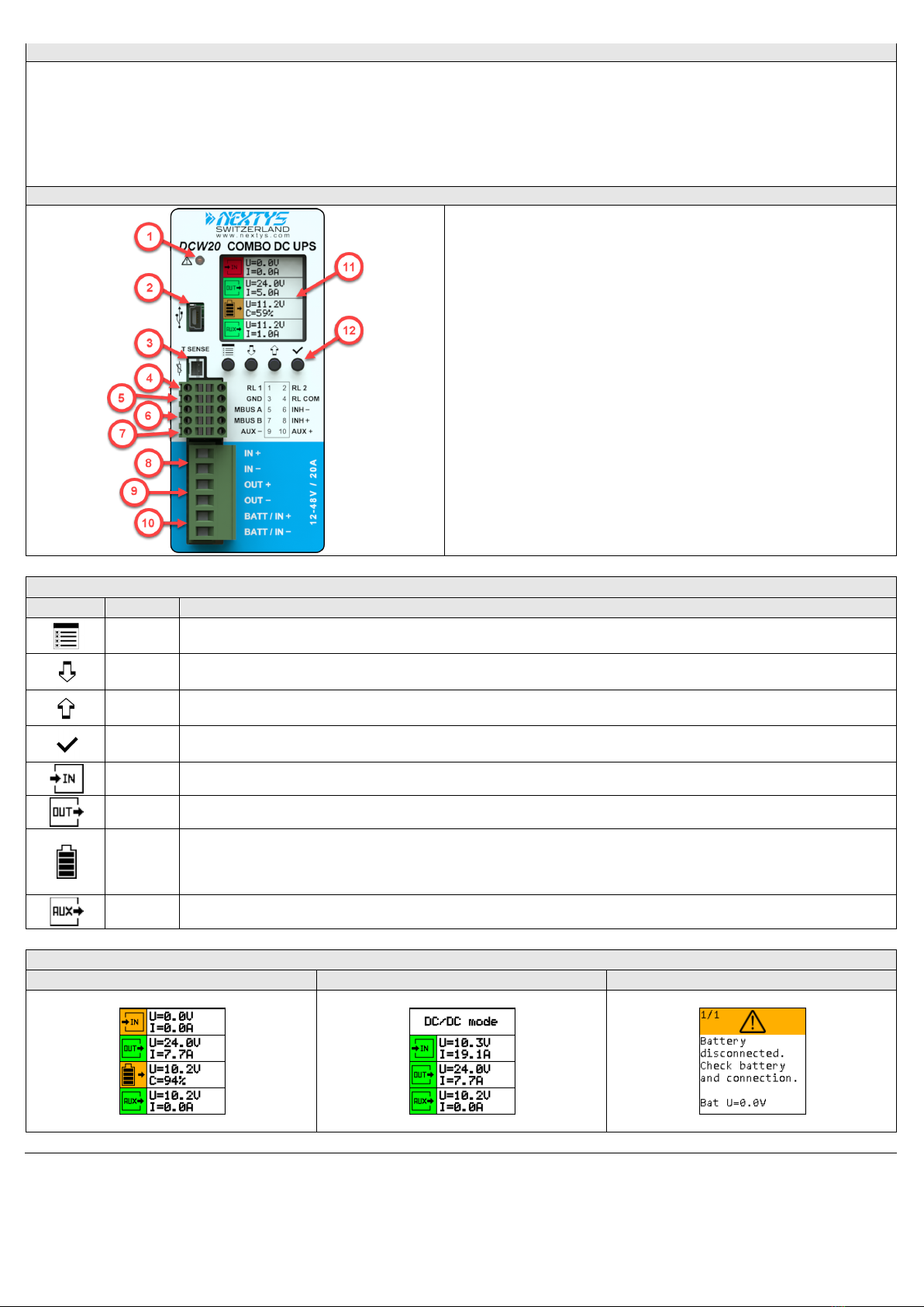
Connections and User interface
1. Alarm LED indicator: ON when the unit is in backup. Blinks at 1Hz rate in case of
error.
2. Modbus RTU over USB: Used to connect a PC running POWERMASTER or custom
application for remote monitoring and controlling. Firmware update is also possible
through USB connection.
3. Temperature sensor: Optional temperature sensor (P/N: WNTC-2MT) to measure
the battery temperature for protection and temperature compensated charge method.
4. Relays dry contacts: 2 relays are present for remote monitoring.
5. Modbus RTU over RS485: Used to connect a PC running for remote monitoring and
controlling. Firmware update is also possible through RS485 connection.
6. Inhibit input: A voltage between 5VDC and 30VDC applied to this input activates the
inhibit function.
7. Auxiliary output supply: Maximum 5A supply from the battery (unregulated).
8. Input connection: 2 poles are provided for input connection. This must be
connected to a power supply rated 12…48VDC.
9. Output connection: 2 poles are provided for output connection. It must be
connected to the load to be backed up.
10. Battery connection: 2 poles are provided for battery connection. This must be
connected to the battery. Please respect the correct polarity.
11. Display area: provides information regarding the device status.
12. Control keys: 4 push buttons are provided to navigate through the menus and to
select the various functions.
User Interface
Symbols
Name
Function / Description
MENU Key Scrolls between menus.
DOWN Key Scrolls down menus and values.
UP Key Scrolls up menus and values.
OK Key Confirms selection.
INPUT The measured input voltage and current is shown in this section.
OUTPUT The measured output voltage and current is shown in this section.
BATTERY
The battery voltage, current, temperature, resistance and charge are shown in this section. During charging and discharging the symbol
background color changes to orange and the number of bars drawn inside reflects the charge status. During discharging and charging an
arrow drawn beside the symbol reflects the direction of the current flowing through the battery, pointing towards the battery during
charging. Battery section is not present in DC-DC mode.
AUXILIARY The measured auxiliary output voltage and current is shown in this section.
MODE displayed
UPS status screen
DC-DC status screen
Alarm screen
3
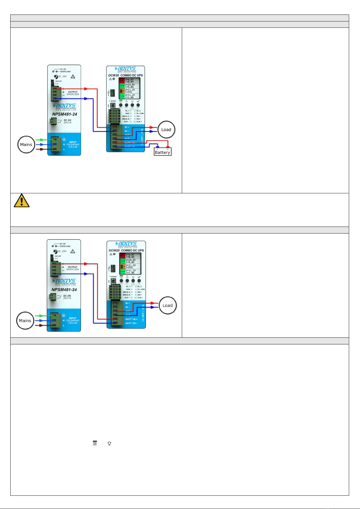
Operating MODE
UPS Mode
UPS Mode:
In UPS mode the DCW20 protects a load from unwanted power interruption in
case of mains failure. An example of UPS connection is given on to the side.
When the input is present DCW20 acts as a bypass, connecting the input to the
output via the input switch. Meanwhile, if required, the battery is charged.
During bypass there is no voltage conversion, therefore the output supply voltage
is equal to the input voltage.
In case of power outage, the DCW20 takes energy from the battery to keep the
output regulated at “Nominal output voltage”.
Backup:
The system is in backup mode if the supply for the output is sourced from the
battery (input supply missing). During backup the battery is monitored
continuously to prevent over discharge.
A programmable backup timer is also implemented in order to fix a maximum
backup time during power outages. This allows preserving the battery life and
shortening the recharge time, avoiding discharging the battery when not needed.
During backup the internal Coulomb counter is used to give an estimate of the
residual charge of the battery.
Backup starts when the output voltage is lower than 90% of the “Nominal output
voltage”.
Battery charger:
The battery charger supports various chemistries such Lead-Acid, Nickel, Lithium
and Super-capacitors. Other charging algorithms can be implemented by request
(contact factory).
The battery charger automatically reduces the current to avoid exceeding the
maximum input current in case of high current load.
Warnings:
- In order to avoid potentially hazardous situations including fire hazard, safety recommendations must be followed. Only authorized staff can install the unit.
- For Lithium cells the balancing and protection circuit must be included in the battery pack.
- For Nickel batteries the use of the external temperature sensor is mandatory. The sensor must be placed in contact with the battery.
DC-DC Mode
DC-DC Mode:
DCW20 can be used as a high performance DC/DC converter. An example of
DC/DC connection is given on to the side.
Any voltage between 10V to 55V can be converted to any voltage between 10V
to 55V (step-up and step-down operation) with up to 20A input or output
current.
Input and output are protected against over current with user settable limits.
When used as a DC/DC converter the input supply must be connected to the
battery connector as shown on to the side.
Additional Functions
Battery health monitor
•Internal resistance measurement: The resistance is periodically measured. The internal resistance is a good indicator of the battery health status; a sudden increase
of the internal resistance indicates a potential problem on the battery or on the battery wiring.
•Temperature measurement: The battery temperature is monitored through an optional temperature sensor (P/N: WNTC-2MT). The battery charger takes into
account the battery temperature and provides a temperature compensated charging voltage. In case of over or under temperature the system disconnects the
battery to prevent damage.
•Coulomb counter: Estimates the remaining battery capacity and consequently the available backup time.
•Deep discharge protection: It protects against the deep discharge of the battery which can lead to its irreversible damage.
Cold Start:
The cold start is a procedure that allows turning ON the UPS without the input power. This procedure is used to turn ON the UPS to operate during a power interruption.
This practice is also a method to see if the battery connected to the DCW20 is functional. In cold start the DCW20 will remain ON for at least 60 seconds independently
from the battery voltage being under the deep discharge threshold, the inhibit input and the backup timer. After the first 60 seconds the device stays ON until the battery
is not deep discharged, the backup timer is not expired or the inhibit input is not active. If the input supply returns during cold start the device reverts to normal
operation.
To cold start the DCW20:
•Press and hold simultaneously the and buttons until you see the welcome message on the screen. On the status screen the "Cold start” text is written beside
the input icon.
•Release the buttons.
PC shutdown and automatic restart:
•PC shutdown: In case the DCW20 is used to supply a PC it is possible to automatically shut down the PC after an adjustable time of backup. For this the PC must run
the POWERMASTER application (provided free) and must be connected through Modbus. Optionally POWERMASTER can call a task on the PC before shutting down,
for example to backup some sensitive data.
•Automatic restart: DCW20 is able to automatically restart a PC which was powered OFF by mistake, for example in case of the Operating System (OS) crash. The
4
user may adjust an output current threshold and a timer used for detecting the PC OFF status. In order to restart the PC the DCW20 toggles the output OFF and
then ON again. User must enable in the PC BIOS the automatic start in case of supply ON.
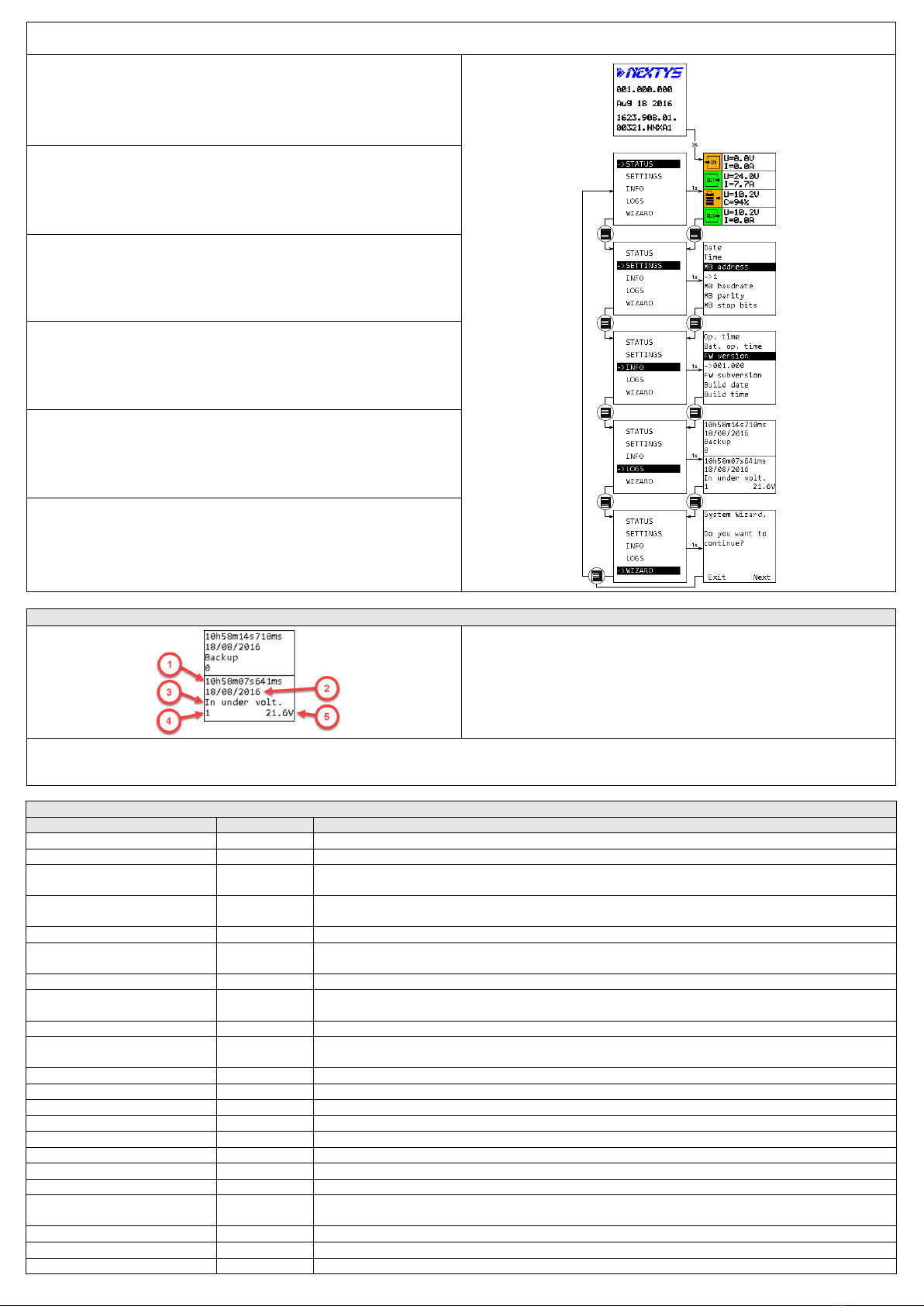
Power ON screen:
This screen is shown at power ON.
It shows the device name, serial number and firmware version.
Status:
This is the default view where the user can find the most relevant information about
the device status. The system always falls back to this view after 60s of inactivity (no
key pressed).
Settings:
All the device settings are configurable from this menu.
Use the UP/DOWN KEY to navigate through the parameters.
Press the OK KEY to enter/exit the editing mode.
In editing mode use the UP/DOWN KEY to change the highlighted value.
Info:
Device information such as firmware version, serial number and device name is
visible from this menu.
Logs:
All the alarms and event are logged in a circular buffer and visible from this screen.
Use the UP/DOWN KEY to navigate through the logs.
Wizard:
The wizard helps the user to configure the system through a series of screens.
LOGS
1. Time: time at which the log occurred.
2. Date: date at which the log occurred.
3. Name: unique log name
4. Primary value: optional.
5. Secondary value: optional.
Every event is logged in the device FLASH memory. From the log menu the user can view their history. Use the UP/DOWN KEYS to navigate between logs, 2 logs are visible
simultaneously on the LCD. Logs are of 3 different kinds: info, alarms and events. All info and alarms have an associated Modbus field with the current status (0 if inactive
or 1 if active). For info and alarms a log is generated at each status transaction. In case of active alarm the front LED and the buzzer turn ON.
Alarms
Type
LCD name
Description
Battery disconnected
Bat. discon.
Active when no battery is detected by DCW20.
Battery Ri too high
Bat Ri too high
Active when measured battery internal resistance exceed the alarm threshold
Battery under temperature Bat under temp.
Active when the battery measured temperature (using the optional external sensor) is under the threshold
specified in “Battery min. temperature” field. If active the battery charged is disabled.
Battery over temperature Bat over temp.
Active when the battery measured temperature (using the optional external sensor) exceed the threshold
specified in “Battery max. temperature” field. If active the battery charged is disabled.
Battery lifetime elapsed
Bat lifetime
Active when the actual calculated battery lifetime exceeds the threshold specified in “Battery lifetime” field.
Battery charge failure Bat charge fail
Active when DCW20 could not charge the battery correctly. When active, the battery charger is disabled.
Disconnect the battery to reset the alarm.
Battery SoC < 25%
Bat SoC 25%
Active when the battery State of Charge is under 25% of the nominal full charge capacity.
Battery over discharge current Bat over dis. I
Active when the measured battery discharge current reaches the threshold specified in “Battery max. discharge
current” field.
Battery low
Bat low
Active when the measured battery voltage is under the threshold specified in “Battery low voltage” field.
Battery deep discharged Bat deep disch.
Active when the battery measured voltage is under the threshold specified in “Battery deep discharge voltage”
field.
Backup
Backup
Active when the system is in backup.
Input under voltage
In under volt.
Active when the measured input voltage is under 90% of the “Nominal output voltage” field.
Input over voltage
In over volt.
Active when the measured input voltage exceeds 120% of the “Nominal output voltage” field.
Output under voltage
Out under volt.
Active when the measured output voltage is under 90% of the “Nominal output voltage” field.
Output over voltage
Out over volt.
Active when the measured output voltage exceeds 120% of the “Nominal output voltage” field.
Output overload
Out overload
Active when the measured output current reaches the threshold specified in “Max. output current” field.
Input over current
In over cur.
Active when the measured input current reaches the threshold specified in “Max. input current” field.
Auxiliary output overload
Aux overload
Active when an excessive load is detected on the auxiliary output.
External temperature sensor error Ext. T error
Active when the external temperature sensor is not connected while it’s use is mandatory like in NiMh battery
charging.
Backup time left < 25%
Bkp left 25%
Active when the system is in backup and the maximal backup time is less than the “Max. backup time” filed.
Warning over temperature
Warn. over T
Active when the internal temperature is high. If the temperature increases more the device may switch OFF.
Error over temperature
Error over T
Active when the internal temperature is too high. To prevent damage the device switches OFF.

5
Events
Type
LCD name
Description
Power ON event
Power on
Generated at every time the DCW20 is turned ON.
Shutdown event
Shutdown
Shutdown reason:
1 - Deep discharge
2 - Max. backup time elapsed
3 - Shutdown command
4 - Reset command
5 - Inhibit signal
Battery cycle triggered by
Bat. cycle triggered by
0 - Schedule
1 - User
Battery cycle ended by
Bat. cycle ended by
Battery cycle end reason:
1 - State of charge
2 - Time limit
3 - Input under voltage
4 - Battery in charge
5 - User
Mounting / Dismounting Instructions
For DIN rail mounting according to IEC 60715 TH35-7.5(-15). Mounting as shown in figure, with input terminals on lower side, with suitable cooling and maintaining a
proper distance between adjacent devices as specified in the User manual.
Mounting
1.Tilt the unit slightly backwards.
2.Fit the unit over the top edge of the
rail.
3.Slide it downward until it hits the
stop.
4.Press against the bottom for locking.
1
2
3
4
Dismounting
1.Pull down the slide clamp lever.
2.Tilt the unit upward.
3.Unhook the unit from the rail.
1 & 2
3
Dimensions
Distances
Dimension
W
H
D
mm
54.0
115.0
110.0
Distance
A
B
mm
20
50

6
Recommended connecting cable
Recommended Tightening torque
IN / OUT / BATT IN connections
0.5Nm
5 Lb.in
Auxiliary connections
Insertion force per pole
Max 3N or 0.674 lbf
Withdrawal force per pole
Min 1.5N or 0.337 lbf
IN / OUT / BATT IN connections
Solid: 2.5mm² / 12AWG
Stranded: 2.5mm² / 12AWG
L: 7.0-8.0mm / 0.27-0.315in
Auxiliary connections
Solid: 0.75mm² / 18AWG
Stranded: 0.75mm² / 18AWG
L: 7.0-8.0mm / 0.27-0.315in
NOTES

7
Other manuals for DCW20
1
Other nextys Media Converter manuals


Popular Media Converter manuals by other brands

Danfoss
Danfoss VLT AQUA Drive FC 202 operating guide

Car Solutions
Car Solutions NAVI5CH installation guide

AV Access
AV Access 4KCVH2H user manual

Lika
Lika Rotomag MSK36 Series Mounting instructions

Cary Audio Design
Cary Audio Design DAC-100 owner's manual

Theatrixx
Theatrixx xVision Converter Series Quick-Start Streaming Guide


