Lumel PD9 User manual

PD9-09 Service Manual
1
CONVERTER RS-485/ ETHERNET
PD9
SERVICE MANUAL

PD9-09 Service Manual
2
Contents
1. Quick Start.................................................................................................................................................3
1.1. Hardware Testing Environment..........................................................................................................3
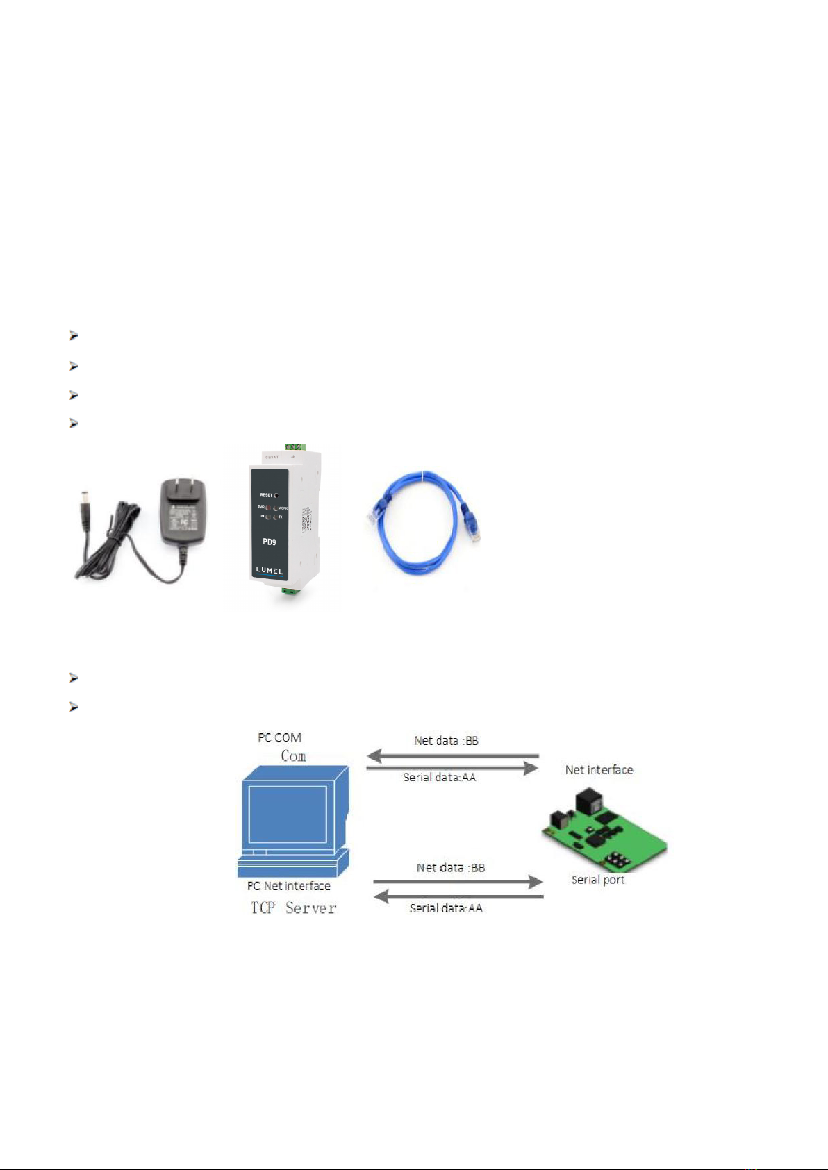
1.1.1. Hardware Prepare.......................................................................................................................3
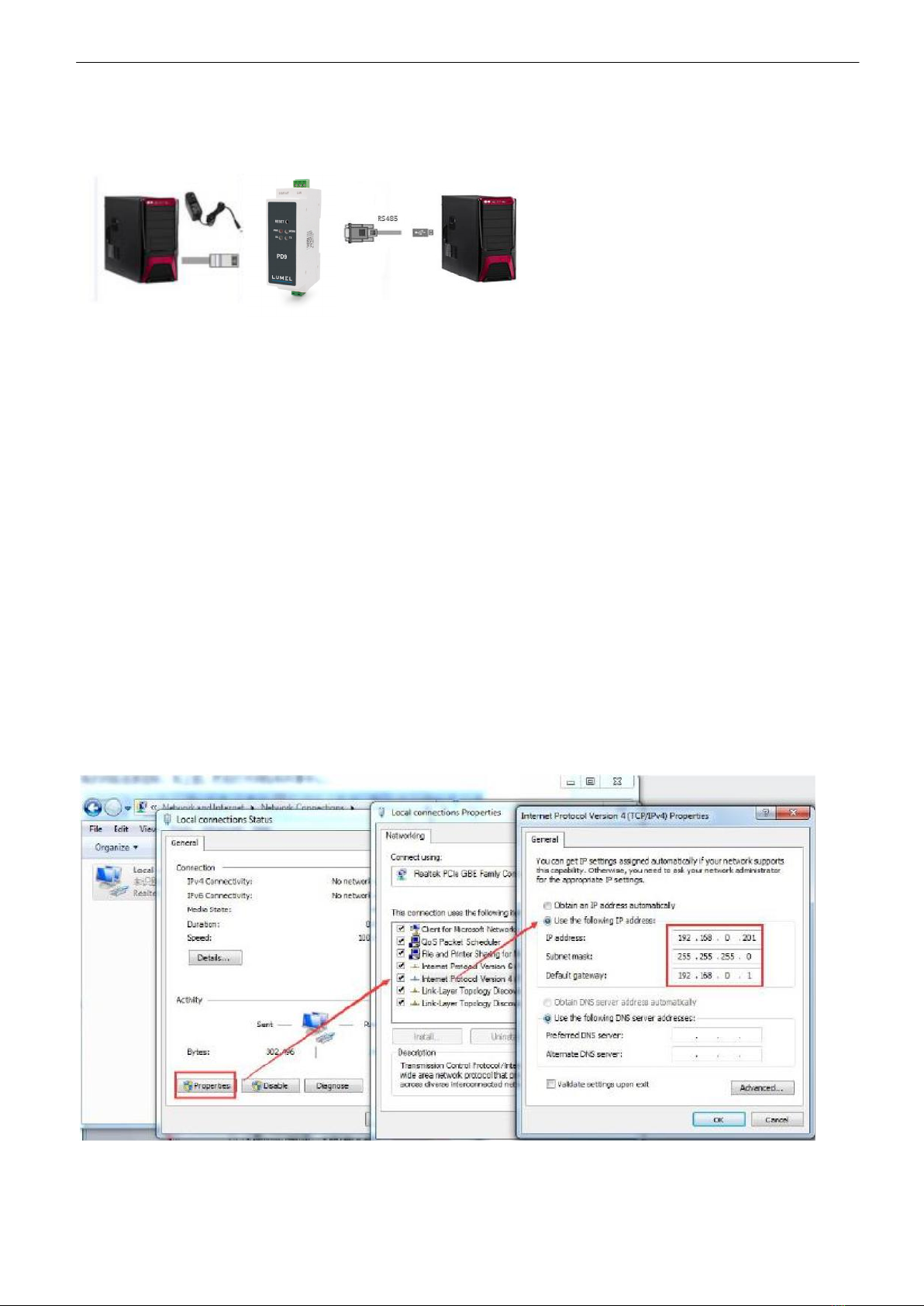
1.1.2. Hardware Connection..................................................................................................................4
1.2. Network Test Environment .................................................................................................................4
1.3. Default Parameter ..............................................................................................................................5
2. Brief Introduction .......................................................................................................................................5
2.1. Introduction ...........................................................................................................................................5
2.2. Features..............................................................................................................................................5
2.3. Basic Parameter.................................................................................................................................6
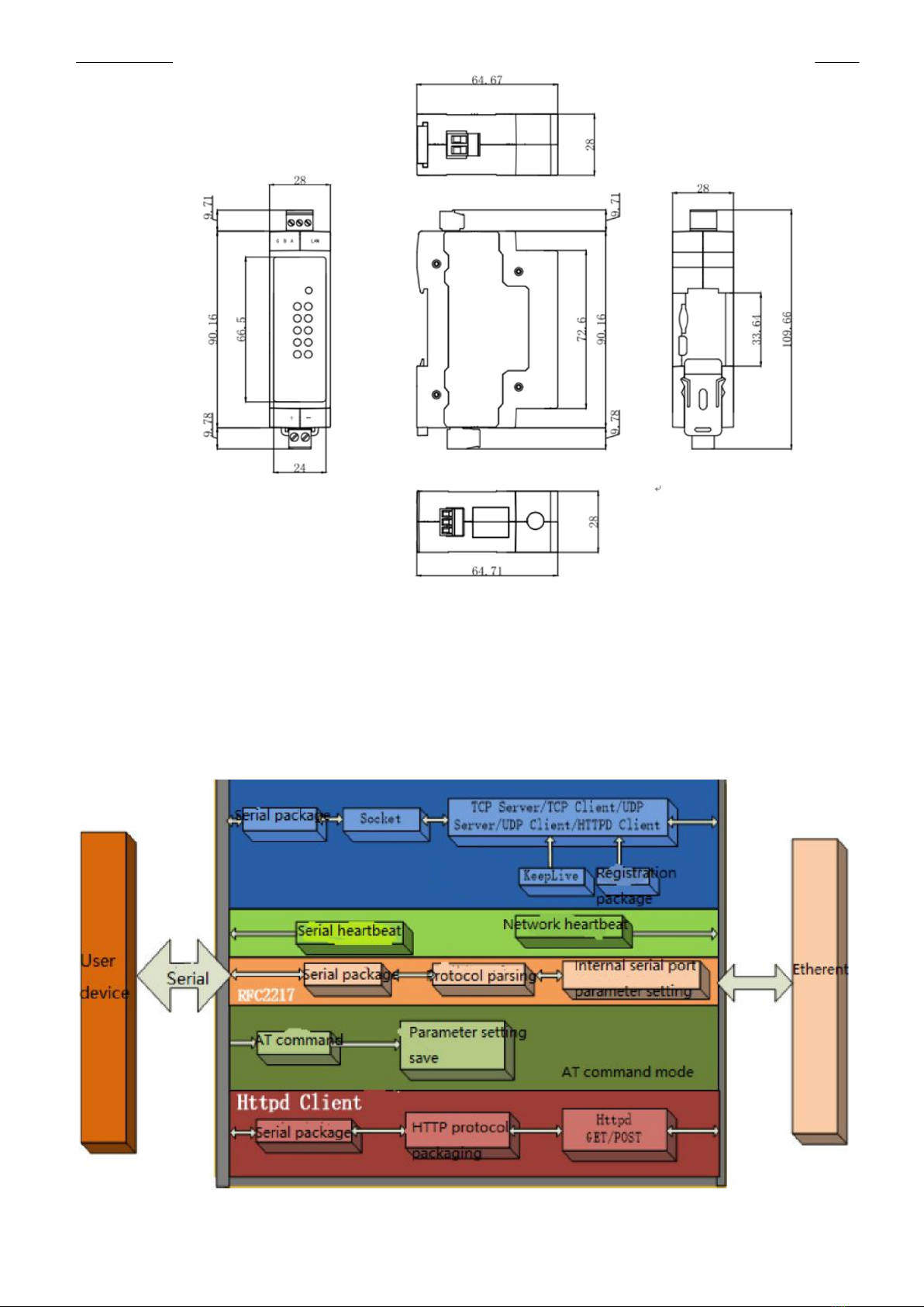
3. Hardware Parameters...............................................................................................................................8
4. Product Function.......................................................................................................................................8
4.1. Network Basic Function .....................................................................................................................9
4.1.1. Static IP/DHCP/Subnet Masks/Gateway....................................................................................9
4.1.2. DNS Server Address.................................................................................................................10
4.1.3. Webserver .................................................................................................................................11
4.1.4. Restore to Factory Set ..............................................................................................................11
4.1.5. Firmware Upgrade ....................................................................................................................12
4.2. Socket Communication.....................................................................................................................13
4.2.1. TCP Client Mode .......................................................................................................................14
4.2.2. TCP Server Mode......................................................................................................................16
4.2.3. UDP Client Mode ......................................................................................................................18
4.2.4. UDP Server Mode.....................................................................................................................19
4.2.5. HTTPD Client ............................................................................................................................20
4.3. Impersistent Connection (TCP Short Link)......................................................................................21
4.4. Clean the buffer data........................................................................................................................22
4.5. Modbus Gateway..............................................................................................................................23
4.6. Other functions..................................................................................................................................24
4.6.1. Heartbeat Packet Function.......................................................................................................24
4.6.2. Registration Package Packet Function ....................................................................................25
4.6.3. The number of the client connected .........................................................................................26
4.6.4. Serial Port Packaging Mechanism ...........................................................................................27
4.6.5. Flow Calculation ...................................................................................................................27
5. Setting Protocol.......................................................................................................................................28
5.1. Network Setting Protocol..................................................................................................................28
5.1.1. Set Parameter Process ............................................................................................................28
5.1.2. Setting Command Content........................................................................................................28
5.1.3. Commands’ Return Content .....................................................................................................34
5.1.4. Listening Report Method ..........................................................................................................37
6. Parameter Configuration.........................................................................................................................37
6.1. Software Configuration .....................................................................................................................37
6.2. Webpage Configuration ....................................................................................................................40

PD9-09 Service Manual
3
1. Quick Start
Module PD9 is used to realize data transparent transmission between Ethernet interface and the serial port and the protocol
converter. The serial port is the RS485 data and in the Ethernet interface, it is the net data package. Users can configure the
parameters via the webpage or set-up software, set one time and save forever
1.1. Hardware Testing Environment
1.1.1. Hardware Prepare
DC5V 1A power adapter (delivered in set)
Network cable
PD9 (delivered in set)
PC
F9ig
1.1.1-
1
Hardware
Prepare
1. Testing Aim
Have a quick recognize to the PD9 and have a basic recognition
Testing is there is any issue in the product.
2. Data Direction
Fig.
1.1.1-2
Data
Direction

PD9-09 Service Manual
4
1.1.2. Hardware Connection
Fig. 1.1.2-1Hardware Connection
PD9 connects to PC by serial port and RJ45 Port. Then power on PD9 with our AC adapter.The above picture will show you the
connection.
Notes:
•Power adapter (5V) and connection cable are provided in delivery set.
•RS485 is involved.
•PCs in above picture is the same one.
1.2. Network Test Environment
Please check PC setting after hardware connection.
1) Disable PC Firewall and anti-virus software.
2) Disable the network card nothing to do with testing and just leave one local connection.
3) As for PD9 connect with PC directly, should set static IP for PC, which in the same network segment with PD9, like
192.168.0.201.
Fig.1.2- 1 PC Local Connection Configuration

PD9-09 Service Manual
5
1.3. Default Parameter
Default parameter is as below:
Item
Content
User
name
admin
Password
admin
IP
address
192.168.0.7
Subnet
mask
255.255.255.0
Default gateway
192.168.0.1
Def
ault work mode of port
TCP
Client
Default
remote port
8324
Default
local port of port
0
Remote
IP address
192.168.0.201
Baud
Rate
115200
Parity
bit/Data bit/Stop bit
None/8/1
Table 1.3-1 Default Parameters
`2. Brief Introduction
2.1. Introduction
PD9 Modbus RS485 to Ethernet converter can realize bidirectional transparent transmission between RS485 and Ethernet. It
carries ARM processor, low power, fast speed, high stability. Via web-page or software, rs485 to Ethernet Converter can realize
serial data and TCP/IP data package transparent transmission.
2.2. Features
ARM base on Cortex-M0 kernel, and reliable TCP/IP protocol stack
Industrial working temperature range from -40C ~85C
Auto-MDI/MDIX, RJ45 port with 10/100Mbps
Support TCP server, TCP client, UDP server, UDP client, HTTPD client and modbus TCP work mode
Serial port baud rate can be set from 600bps to 460.8Kbps, parity: None, Odd, Even, Mark, Space

PD9-09 Service Manual
6
Supports self-defined heartbeat package, keep the connection can never crash
Supports self-defined registration package, check the station of the connection, which also can used as the self-
defined package head. Users can use the MAC as the registration package.
Under the TCP server mode, the number of the client connected to the server can be set from 1-8, default 4. the IP of the
client connected can be dispaly. Each connection calculates the data received/transmitted.
Under the TCP server mode, if the number of the clients number is 8, kick the old one or not can be set.
Configure the parameters via the webpage, AT command, serial protocol and net protocol, provides setting protocol,
and users can put into their software.
Supports TCP client short connection, the disconnection interval can be set.
Supports timeout restart( no data and restart), the restart time can be set.
Before the TCP connection build, client the buffer data or not can be set
Supports DHCP, obtain the IP automatically.
The global unique MAC address bought from IEEE, also users can define MAC address
Supports DNS function, and analyze the domain name. The DNS server address can be set.
Upgrade firmware via network.
Supports hardware and software restore default settings
Running across the gateway, converter and the router
Running in LAN or in access the external net.
2.3. Basic Parameter
Classify
Parameter
Value
Hardware
Parameters
Input
Voltage
DC5
~36V
Working
Current
130mA@5V
Net
interface format
RH45,10/1000Mbps
Serial
baud rate
600~460.8K(bps)
Serial
port
RS485*1
Software
parameters
Net
protocol
IPV4,
TCP/UDP,
ARP,
ICMP,
IPV4
IP
access way
Static
IP,
DHCP
DDNS
supports

PD9-09 Service Manual
7
User
Configuring
Software
configuring and webpage configuring AT command
Transmit
way
TCP
server, TCP client, UDP server, UDP client
Similar
RFC2217
support
HTTPD
client
support
TCP
server
At
most support 8 TCP client to connection
Net
buffer
Send:16Kbyte;
receive:4Kbyte
Serial
buffer
receive:1Kbyte
Average
delay
<10ms
Related
software
set
-up software
Packaging
mechanism
4
bytes packaging time, 1024 bytes packaging length.
Others
Certification
CE,
FCC, ROHS
Protection
1.5KV
electromagnetic isolation
Dimension
71.0*60.0*25.0mm(L*W*H)
Operating
Temp.
-
40~+85°C
Storage Temp
-40~105°C
Operating
Humidity
5
~95%RH
Storage
Humidity
5
~95%RH
Packaging
Electrostatic
bubble
Fig.
2.3-1
Basic
Parameters

PD9-09 Service Manual
8
3. Hardware Parameters
Fig.
3-
1
Dimension
4. Product Function
Fig.
4-
1
PD9
Function
Diagram

PD9-09 Service Manual
9
4.1. Network Basic Function
4.1.1. Static IP/DHCP/Subnet Masks/Gateway
1. The IP of the module is the symbol in the LAN, which can be distinguish from the other device.
Static IP
Manual setting the static IP, meanwhile please writing the IP, subnet and gateway. Static IP adjust to the scenario
that P and the device correspond.
Advantage: the device access to the IP that can not distribute can searched by the broadcast
Disadvantage:different segment of the different LAN need to configuring.
DHCP
The DHCP is to obtain the IP, gateway and DNS from the gateway automatically to reduce the tedious step for setting the IP.
Adjust to the scenario there is no requirement to the IP.
Advantage: communicate directly when access router which can distribute the DHCP to reduce the tedious step to set the IP and
the subnet masks.
Disadvantage:access the net without DHCP, just like connect the PC directly, the module can not work normally.
Related AT command:
Command
name
Instr
AT+WANN
Setting and
query the IP access way, subnet and the gateway parameters of the PD9
Table 4.1.1-1 Related AT Command
2. Subnet masks: to mark which subnet is the host in from the IP address bites and which bites mark the host masks.
3. Gateway: IP address of the router in the LAN, if there is something wrong with the setting, user will can not access the
external net. If user do not use the router and so on device, keep default and do not set.
4. Setting software.

PD9-09 Service Manual
10
Fig. 4.1.1-1 Setting Software
4.1.2. DNS Server Address
DNS server is used to converter the domain name in to the IP address that net can recognized. The server address of the PD9
can be configured. After setting, all the questing will be sent to this address when the PD9 need to DDNS.
Under the static IP mode, DNS server address default is 8.8.8.8. and under the DHCP mode, DHCP server address can be
acquire automatically.
Fig.
4.1.2-
1
Local
IP
Config
Related AT command:
Comman
d name
Instr
AT+DNS
Setting
and query the DNS server address of the PD9
Table 4.1.2-1 Related AT Command

PD9-09 Service Manual
11
4.1.3. Webserver
PD9 supports build-in webserver, same as the normal webserver. User can setting the parameters via the webpage also
can check the related status. Default port of the webserver is 80, and this port can be modified/ after modify, user also can
access the build-in webpage to access via the other port.
The default home page is the current state interface, refreshed every 10s, showing PD9 working status:
Total number of data sent by the network: Can judge how much data is sent to the external network.
Total data received by the network: Can determine how much data is sent from the network to the module.
Connected remote IP/network send/receive: Through this item, you can see which device is connected to PD9. How much data
is sent and received by this connection. Currently, only 4 connection status displays are supported.
In UDP Server mode, only the send/receive data is displayed, and the connection IP is not displayed.
Fig. 4.1.3-1 Current Status
4.1.4. Restore to Factory Set
1) Hardware restore:
Press the Reload button for 5s to 15s to restore the factory settings. If it is less than 5s or exceeds 15s, the factory reset will not
be performed. When the module is configured with incorrect parameters, or if you have forgotten the previously set password,
you can restore the factory settings.
2) Software restore:
Restore the factory settings by setup software setting function or send the factory reset command via the network protocol.
3) AT command restore:
Enter the AT command mode, restore via the command.
Related AT command:
Command
name
Instr
AT+RELD
Restore
to factory setting

PD9-09 Service Manual
12
Table 4.1.4-1 Related AT Command
4.1.5. Firmware Upgrade
The way to upgrade the PD9 firmware is to upgrade through the network. It is simple and convenient to upgrade the firmware
through the network. By upgrading the firmware, you can get more cutting-edge applications. The specific upgrade method is as
follows.
1) Upgrade the firmware with awired network. Before upgrading, turn off the wireless and virtual machine network cards
to ensure that the computer only keeps one wired network card. The module and the computer can be connected to the router at
the same time or the module can be directly connected to the computer.
2) After the hardware is connected, upgrade the firmware by setup software, do not change the IP and MAC addresses,
set the firmware path (it is recommended not to have a Chinese path), and then click to upgrade the firmware.
3) There is a progress bar during the upgrade. When the progress bar reaches 100%, the setup software will prompt that
the upgrade is successful and the upgrade is complete. Re-search the module after the upgrade is complete.

PD9-09 Service Manual
13
4.2. Socket Communication
There are five work modes for the socket of the PD9:TCP Client, TCP Server, UDP Client, UDP Server, Httpd Client.
Set via the webpage or the set-up software
The webpage are as bellows:

PD9-09 Service Manual
14
Related AT command
Command
name
Instr
AT+SOCK
Setup PD9 Socket working mode / target IP / target port
4.2.1. TCP Client Mode
Fig. 4.2.1-1 TCP Client
1) TCP client provides the client connection for TCP net server. Query the server automatically can build the connection to
realize the data transmission. Different from UDP mode, in this mode, connection has status of disconnection and remaining to
make sure the data transmission reliable.
2) Identify disconnects. After connection built, it sends keepalive searching packet every 15 seconds. Once there is an
interrupt, it can be detected rapidly then make PD9 disconnect from former connection and reconnect.
3) Please notice the remote IP/domain name and the remote port when connecting the TCP server. Remote IP can be the
device in the same LAN or the device in other LAN. If user want to connect the server across the net, there must be a public IP
or the domain name for the server.
4) It supports Synchronous baud rate (Similar RCF2217), also supports short connection function.
5) Under the same LAN, if 302 is set to static IP, keep the IP and gateway of 302 in the same network segment, and set the
gateway IP correctly. Otherwise, communication will not be possible.
6) PD9 work as TCP Client, It connects to the target IP/Port automatically,will not accept other connection request.
7) When 302 is used as the TCP Client, it is recommended to set the local port number of 302 to 0. In this way,
302 can access the server with a random port number, which can solve the problem of reconnection failure caused by the
server determining that the connection state is abnormal.
8) Test
①Open PD9Config software.
Set PD9 as TCP Client, Destination IP: 192.168.0.201. Destination port:8234.
Save the parameters and then research again to check if the parameters are correct . Also users can set the work mode
,remote IP and the remote port via the webpage.
PD9

PD9-09 Service Manual
15
Fig. 4.2.1-2Configuration
Fig. 4.2.1-3 Serial Port

PD9-09 Service Manual
16
4.2.2. TCP Server Mode
Fig.
4.2.2-
1
TCP
Server
Mode
1) PD9 In the TCP Server mode, there is also a KeepAlive function for real-time monitoring of the integrity of the connection.
2) Usually used for communication with TCP clients in the LAN. It is suitable for scenarios where there is no server in the
LAN and there are multiple computers or mobile phones requesting data from the server. As with TCP Client, there is a
difference between connection and disconnection to ensure reliable exchange of data.
3) This mode supports independent synchronous baud rate function (RFC2217) function.
4) In TCP Server mode, the PD9 actively listens to the local port and responds with a connection request and creates a
connection. When the serial port of the PD9 receives the data, it also sends it to all devices that establish a connection with the
PD9 server. If you access the PD9's TCP server across the public network, you need to do port mapping on the router.
5) It support 8 clients connections at max. (the number can be set.) the local port is fixed, can not be “0”
6) Under TCP Server mode, when the number of connected clients exceeds the set maximum value, the default is to replace
the old connection with a new one, can modify this function in the web page.
7) Test Example
①Set PD9 as TCP Server Mode, local port 20108, same as default. Also can set in the webpage.
PD9

PD9-09 Service Manual
17
Fig. 4.2.2-2 TCP server mode (software)
Fig. 4.2.2-3 TCP server mode (webpage)

PD9-09 Service Manual
18
4.2.3. UDP Client Mode
Fig.
4.2.3-
1
UDP
Client
1) It subjects to UDP protocol, no connection, just only sending data. No difference of the connection and disconnection,
no requirement with the packet loss, small data package and quick frequency and the data sent to the appointed IP.
2) PD9 only communicate with destination port of IP. Otherwise, the data cannot be received.
3) Under this mode, destination Address is 255.255.255.255, then it can make UDP broadcast and receive broadcast
data. The firmware in the 4015 and later firmware supports the broadcast in the network segment, such as the broadcast mode of
xxx.xxx.xxx.255
4) Multicast is not supported in UDP mode.
5) Example:
①Open PD9Config, E45 Setup Software: Set PD9 to UDP client mode and the target port is 8234.
Fig. 4.2.3-2 UDP Client (software)
PD9

PD9-09 Service Manual
19
Fig. 4.2.2-3 TCP server mode (webpage)
4.2.4. UDP Server Mode
Fig.
4.2.4-
1
UDP
Server
Mode
1) Base on normal UDP, it doesn't verify source IP address. Every time PD9 receive one UDP data packet,
it changes destination IP to where data comes and it sends the data to the IP and port which communicate latest.
2) Used in the scenario several net device want to communication with the module with high speed and do not want to use the
TCP mode.
PD9

PD9-09 Service Manual
20
4.2.5. HTTPD Client
1) In this mode, the user's terminal device can send request data to the specified HTTP server through PD9, and then PD9
receives the data from the HTTP server, parses the data and sends the result to the serial device.
2) User do not need to pay attention to the data conversion process between the serial port data and the network data packet,
and the data request of the serial port device to the HTTP server can be realized by simple parameter setting.
3) When PD9 sends data to HTTP server via serial port, set the URL, header remote domain name, IP and port and save, then
it only needs to send the header of requested data; PD9 will automatically add information such as URL and header. The returned
data, user can choose whether to remove the header.
4) Test example:
Fig.
4.2.5-
1
Httpd
Client
web
page
settings
1. Set PD9 as HTTPD Client in webpage, and set the corresponding target port number and destination IP/domain
name.
2. Set the Httpd request method and the URL and header information of the request packet at the web page.
3. Whether the header of the information replied by the Httpd server is removed can also be set in the web page.
4. After the setting is completed, click Save and restart PD9 to take effect.
5. Open the serial port to send data, then the serial port data will be submitted to the web server, and the serial port will also
receive the information replied by the server.
6. For details on sending a request, refer to the "Httpd Client Mode Description" Fig., as shown below:
Other manuals for PD9
2
Table of contents
Other Lumel Media Converter manuals