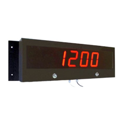
Fema Electronica BDF-24 User manual

Series : BDF-24 & 26
BDF-44 & 46
OPERATOR'S MANUAL
FOR
LARGE DISPLAYS
CentroIndustrial Santiga
Altimira14(Talleres14,Nave2)
Tel.:(+ 34) 93 729 6004 Fax :(+ 34) 93 729 6003
P.O.Box 49
E08210-BARBERÀ DELVALLÈS
(SPAIN)
[email protected] www.fema.es
MODELS
Totalizers : T1, T2, T3, T5 & T6
Rate : TF
13/97 Rev. 2409/01

Page : 2
CONTENTS
DESCRIPTION SECTION PAGE
===========================================================================
IMPORTANT SAFETY CONSIDERATIONS 13
UNPACKING AND INSPECTION 24
MAIN FEATURES 34
MODELS 45
MODEL BDF-XX-T1, TOTALIZER WITH INHIBIT FUNCTION 4.1 5
MODEL BDF-XX-T2, TOTALIZER WITH UP/DOWN CONTROL 4.2 5
MODEL BDF-XX-T3, TOTALIZER UP/DOWN WITH SEPARATE INPUTS 4.3 5
MODEL BDF-XX-T5, TOTALIZER UP/DOWN WITH QUADRATURE CONTROL 4.4 5
MODEL BDF-XX-T6, TOTALIZER UP/DOWN WITH QUADRATURE CONTROL MULTIPLIED BY 4 4.5 5
MODEL BDF-XX-TF, RATE 4.6 5
GENERAL SPECIFICATIONS 56
FRONT VIEW, DESCRIPTION 66
REAR VIEW, DESCRIPTION 76
SIGNAL INPUT PARAMETERS , TRIGGER, COUNT FREQUENCY ,
AND SENSOR TYPES SELECTION 87
WIRING 98
POWER SUPPLY, RECOMMENDED WIRING 9.1 8
FUSES 9.2 8
RESET AND CONTROL FUNCTIONS 9.3 8
EXCITATION VOLTAGE FOR SENSORS 9.4 8
SENSOR CONNECTIONS FOR MODELS
BDF-XX-T1,BDF-XX-T2 andBDF-XX-TF 9.5 9
SENSOR CONNECTIONS FOR MODEL BDF-XX-T3 9.6 9
SENSOR CONNECTIONS FOR MODEL BDF-XX-T5 and BDF-XX-T6 9.7 9
INSTALLATION 10 10
MECHANICAL DIMENSIONS 11 10
JUMPER's CONFIGURATION 12 11
STANDARD CONFIGURATION 12.1 11
PROCEDURE FOR CHANGE THE CONFIGURATION 12.2 11
WARRANTY 13 12
OTHER PRODUCTS 14 13
OPERATOR´s NOTES 15 14
CUSTOMER SERVICE CARD 16 15
DECLARATION OF CONFORMITY 16

Page : 3
INSTALLATION
PRECAUTIONS.- Theinstallationandthe
future use of this unit
must be done by suit-
able qualified person-
nel.TheunithasnotAC
(mains)switch,itwillbe
inoperationassoonas
power is connected.
The installation must
incorporateanexternalmainswitch.
The unit has a protection fuse incorporated on the AC socket, if it is
necessary to change or replace, use the fast fuse according DIN
41661andthevaluesindicatedbelow.
200 mA when the unit is operating at 230 Vac
400 mA when the unit is operating at 115 Vac.
Install also the necessary devices to protect the operator and the
process when using the unit to control a machine or process where
injurytopersonnelordamagetoequipmentorprocess,mayoccuras
a result of failure of the unit.
See paragraph 9, WIRING and paragraph 8, SIGNAL INPUT
PARAMETERSandcheckthatalljumpersareonthecorrectposition.
SAFETY PRESCRIPTIONS.-
TheunithasbeendesignedandtestedunderEN-61010-1rulesand
isdeliveredingoodcondition.Thisopera-
tor's manual contains useful information
for electrical connections. Do not make
wiring signal changes or connections
whenpoweris
applied to the unit. Make signal connec-
tionsbeforepowerisappliedand,ifrecon-
nection is required, disconnect the AC
(mains) power before such wiring is at-
tempted.
Installtheunitin placeswithagoodventilationtoavoidtheexcessive
heating.Andfarfromelectricalnoisesourceormagneticfieldgenera-
torssuch aspower relays,electrical motors,speed controlsetc...
The unit cannot be installed in open places. Do not use until the
installationisfinished.
POWERSUPPLY.-
Thepowersupplymustbeconnectedtotheadequateterminals (see
theconnectioninstructions).Thecharacteristicsofthepowersupply
areshowedonthelabelontherearpart.Pleasemakesurethattheunit
is correctly connected to a power supply of the correct voltage and
frequency.
Donotuseotherpowersupplyotherwisepermanentdamagemaybe
causedtothe unit.
Donotconnecttheunittopowersourcesheavilyloadedortocircuits
which power loads in cycle ON-OFF or to circuits which power
inductiveloads.
SIGNALWIRING.-
Certainconsiderationsmustbegivenwheninstallthesignalinputand
control wires. If the wires are longs can act like an antenna and
introducethe electricalnoiseto theunit,therefore:
Donotinstallthesignalinputorcontrolwiresinthesameconduitwith
power lines, heaters, solenoids, SCR controls etc....and always far
fromtheseelements.
When shielded wires are used, connect the shield to the common
terminalandleaveunconnectedtheotherendoftheshieldanddonot
connecttothemachineground.
1.- IMPORTANT SAFETY CONSIDERATIONS
EXCITATIONSUPPLY Vexc.
The unit supply the excitation voltage to power encoders, pulse
generators,sensorsetc...
Do not connect the Vexc. output terminal to other external power
supply,permanentdamagesmayresulttotheunit.
SAFETY CONSIDERATIONS
PRESCRIPTIONS.-
Before starting any operation of adjustment, replacement,
maintenanceorrepair,theunitmustbedisconnectedfromanykind
ofpowersupply.
Keeptheunitclean,toassure goodfunctioning and performance.
Use for it a clean and humid rag. Do not use for the frontal lens
abrasiveproducts,solvents,alcohol,etc...becauseitstransparence
couldbe damagedand thismaycausedifficultyforacorrectvision
ofthereading.
Topreventelectricalor
firehazard,donotex-
posetheunittoexces-
sivemoisture.
Donotoperatetheunit
in the presence of
flammable gases or
fumes, such as envi-
ronment
constitutes a definite safety hazard. The unit is designed to be
mountedinametalpanel.
Iftheunitshowssignsofdamage,orisnotabletoshowtheexpected
measures, or has been stored in a bad conditions or a protection
failurecanoccur,thendonotattempttooperateandkeeptheunitout
ofservice.
IN CASE OF FIRE
1.- Disconnect the unit from the power supply.
2.-Givethe alarmaccording tothelocal rules.
3.- Switch off all the air conditioning devices.
4.-Attackthefire withcarbonic snow,donotusewater inanycase.
WARNING : In closed areas do not use systems with
vaporized liquids.
CONNECTIONS
All wiring connections are made using push-in cable connectors.
There is a separate connector block for power supply and input
signals. Pleasemakesure thateachconnectorblock isconnected
ontheadequateplace.
Thewirecrosssectionrecommendedforsignalinputsis1mm2and
for power supply 2.5 mm2.
PANEL MOUNTING
Verifythatthepanelcut-outiscorrectlyaccordingtothedimensions
indicated on page 10 with a minimum depth of 150 mm. (5.9").
Install the fixation pieces in the lateral guides of the unit by its rear
partandthenturnthescrew firmlyagainstthepanel,untiltheunitis
totallyholdon.
Seeparagraph10 onpage10.

Page : 4
2.- UNPACKING AND INSPECTION
It is advisable to do a detailed reading of this Manual before mounting the instrument. This Operator's Manual
contains all the technical specifications : electricals as well as mechanics, both necessary to do a correct
installation and also a good use of the instrument.
At the same time the user will acquire the knowledge needed to obtain the best performances of the product.
Check that inside the present cardboard box, there are the following :
1 Instrument Model BDF-XX-T1, T2, T3, T5, T6 or TF.
1 Operator's Manual.
1 Connector for Power Supply.
1 Screw-clamp connectors, 5 pins female for signal inputs.
2 Pieces for fixing the unit against the panel.
If there are some doubts or enquiries about the present instrument, please contact with your Local Distributor
or with FEMA electrónica, s.a.
When the shipment is arrived remove the Packing List and verify that you have received all equipment.
Then inspect the box and the instrument, and if there is evidence of damage caused by bad handling during
the transport, it is advisable to make a careful inspection of all damages making a note of all of them and to
pass on this information directly to the Transport Company.
If this occurs but with insured material, ask the Transport Company for instructions about submitting a claim.
3.- MAIN FEATURES
The Large Displays for Totalizer and Rate are made up by four different series. The main features of
each serie are the following :
Serie BDF-24-XX : 4 digits type LED, seven segments, red or green colour with 57 mm (2.3") height
and minus sign for polarity.
Serie BDF-26-XX : 6 digits type LED, seven segments, red or green colour with 57 mm (2.3") height
and minus sign for polarity.
Serie BDF-44-XX : 4 digits type LED, seven segments, red or green colour with 100 mm (4") height
and minus sign for polarity.
Serie BDF-46-XX : 6 digits type LED, seven segments, red or green colour with 100 mm (4") height
and minus sign for polarity.
The complete reference for each instrument is obtained replacing the ""XX" by the corresponding
references for every Model (T1, T2, T3, T5, T6 & TF). See paragraph 4.

Page : 5
The common features for all series are the following:
MECHANICAL.- Housed in a rugged extruded aluminium profile housing for panel mounting or free standing.
Finished in anodized black colour. The frontal lens is mounted with a special rubber profile
which provides the front part of the unit with an IP-65 protection.
SIGNAL INPUT.- All series have two channel inputs. Channel 1 serves as the count in every Response Mode
and Channel 2 serves as the control function or to count.
Both Channels accept signal generates by NAMUR, PNP or NPN sensor types and contact
closure. Magnetic PICK-UP sensor is only accepted by Channel 1.
CONNECTIONS.- Connections for Signal Inputs or control functions are made using one screw-clamp
connector of five terminals located on the rear part of the unit.
The recommended wire cross section is 1 mm2.
Connection for Power Supply uses a push-in cable connector with 2 terminals for power and
1 terminal for hearth.
The recommended wire cross section is 2.5 mm2.
The fuse is located in the Power Supply socket, as well as the spare fuse.
MEMORY.- Non volatile NOV-RAM type, to maintain stored the software configuration and the value of
the display in case of power failure. It allows 100,000 cycles ON/OFF. The data can be
stored for a maximum of 10 years.
RESET.- By remote push-button using the connector of 5 terminals on the rear part.
DECIMAL POINT.- Programmable by software. Contact your local distributor for additional information.
SCALE FACTOR.-The Scale Factor can be programmed from -5.9999 to 5.9999. Factory Set-up is 1.0000.
Contact your local distributor.
4.- MODELS
4.1.- MODEL BDF-XX-T1, TOTALIZER WITH INHIBIT FUNCTION
Pulses per Channel 1 add up. Channel 2 operates as Inhibit control.
CounterremainsheldduringalltimethattheChannel2remainsconnectedto0Vdc.andruns
free meanwhile Channel 2 is free.
4.2.- MODEL BDF-XX-T2, TOTALIZER WITH UP/DOWN CONTROL
Pulses per Channel 1. Channel 2 operates as UP/DOWN control.
If Channel 2 is connected to 0 Vdc. then the pulses will subtract.
If Channel 2 is free then the pulses will add up.
4.3.- MODEL BDF-XX-T3, TOTALIZER UP/DOWN WITH SEPARATE INPUTS
Pulses per Channel 1 to add up.
Pulses per Channel 2 subtract to the display.
The instrument allows that both pulses in Channel 1 and Channel 2 can be simultaneously.
4.4.- MODEL BDF-XX-T5, TOTALIZER UP/DOWN WITH QUADRATURE CONTROL
Channel 1 serves as the count and Channel 2 serves as a quadrature control.
(See paragraph 9.7).
4.5.- MODEL BDF-XX-T6, TOTALIZER UP/DOWN WITH QUADRATURE CONTROL
Same characteristics of the BDF- XX-T5 including multiplier by 4
4.6.- MODEL BDF-XX-TF, RATE
Pulses per Channel 1. Do not use Channel 2.
The function of this model is to show on the display parameters by time unit, such as
RPM, mts/sec., litters/hour etc...
The minimum frequency allowable is 0.03 Hz.

Page : 6
6.- FRONT VIEW, DESCRIPTION
Models BDF-26-XX
BDF-46-XX
7.- REAR VIEW, DESCRIPTION for all series
Models BDF-24-XX
BDF-44-XX
Fixation screws
Power Supply
Vac + Earth,
fuse and spare fuse.
Channel Inputs and
controls
To be used only
by Technical Service
E
D
C
B
A
5.- GENERAL SPECIFICATIONS
DISPLAY
TYPE . . . . . . . . . . . . . . . . . . . . . . . . 4 or 6 digits, 7 segments, red or
. . . . . . . . . . . . . . . . . . . . . . . . . . . . greenLED.
HEIGHTDIGIT . . . . . . . . . . . . . . . . . 57 (2.3") or 100 mm. (4")
RANGE . . . . . . . . . . . . . . . . . . . . . . -9999to9999or-999999to999999
POLARITY . . . . . . . . . . . . . . . . . . . . Minus only (-)
DECIMALPOINT . . . . . . . . . . . . . . . Programmableposition.
SIGNALINPUTS. . . . . . . Selectableby internaljumpers.
PNP, NPN, NAMUR & Switches . . . Max. input voltage +28 V
Pick-up(Channel1only) . . . . . . . . . Sensitivity : 150 mV.
Hysteresis : 100 mV
Impedance 26.5 KΩat 60 Hz.
Max. input voltage ±50 V.
FREQUENCYINPUT . . . . Selectableby internaljumpers.
ModelsT1 &T2 . . . . . . . . . . . . . . . . 100 Hz or 10 KHz.
ModelT3 . . . . . . . . . . . . . . . . . . . . . 100 Hz or 4 KHz.
ModelT5 . . . . . . . . . . . . . . . . . . . . . 100 Hz or 5 KHz.
ModelT6 . . . . . . . . . . . . . . . . . . . . . 100 Hz or 2.5 KHz.
ModelTF . . . . . . . . . . . . . . . . . . . . . 100 Hz or 10KHz
Minimumallowable0.03Hz.
Accuracy & Repeatibility . . . . . . +0.012 % (Rate only).
OUTPUT
EXCITATIONVOLTAGEOUTPUT . . . +15 Vdc 20%. @100 mA. max.
(TerminalB)
ENVIRONMENTAL
OPERATINGTEMPERATURE . 0 to +50 ºC (32 to 122 ºF).
STORAGETEMPERATURE . . . -20 to +85 º C (-4 to 185 ºF).
RELATIVEHUMIDITY . . . . . . . . 0 to 85 % not condensed.
PROTECTION . . . . . . . . . . . . . . IP65.(Frontpartonly).
MECHANICAL
DIMENSIONS . . . . . . . . . . . . . . See table 5. Page 10.
PANELCUTOUT . . . . . . . . . . . See table 5. Page 10.
DEPTH . . . . . . . . . . . . . . . . . . . See table 5. Page 10.
WEIGHT . . . . . . . . . . . . . . . . . . See table 5. Page 10.
CASEMATERIAL . . . . . . . . . . . Aluminiumextruded.
FINISHED . . . . . . . . . . . . . . . . . Anodized,black colour.
ELECTRICAL
STANDARDPOWERSUPPLY . 230 Vac. ±10% 50 / 60 Hz.
CONSUMPTION . . . . . . . . . . . . See table 5. Page 10.

Page : 7
8.- SIGNAL INPUT PARAMETERS
Hysteresis 0
Logiclevel 0
Logiclevel 1
1Usually the signals to be counted or to be used as signal controls are
producedbyelectronic devicessuch asproximity switches,photocells,
pulsegeneratorsormechanicalclosures.
The electronic sensors type NPN, PNP or NAMUR can be used if the
minimumoutputlevel isnot lowerthan theindicated onthe tablebelow.
NOTE:Thesignal levelsuppliedbyNAMUR sensorsdependsonthe
airgapbetweenthe sensorandthemetal, thereforeitis recommended
to measure the real level logic 1 (ON) and level logic 0 (OFF).
K J H G F E D C B A
S1
S2
CONTROL BOARD
FREQUENCY
INPUT CHANNEL 1 CHANNEL 2
To 100 Hz Jumper J Closed Jumper K Closed
To 10 KHz Jumper J Opened Jumper K Opened
TABLE 2
TABLE 1
If a sensor type NAMUR is used , then the same type
must be used for both Channels.
The unit is provided with damping capacitors for switch
contact debounce. Limits count frequency to 100 Hz.
maximum and input pulse widths to 5 msc. minimum.
Toobtain agoodprotectionselectthe adequatejumpers
asindicated onthetable above.
TABLE 3
Logiclevel1 > 3.75 Vdc. > 7.5Vdc.
Logiclevel0 < 1.5 Vdc. < 5.5 Vdc.
Jumper HClosed(Channel1) H Opened (Channel1)
GClosed(Channel2) GOpened (Channel 2)
INPUT TRIGGER SELECTION COUNT FREQUENCY SELECTION
SENSOR TYPE SELECTION
SENSOR CLOSE JUMPERS
TYPE CHANNEL 1 CHANNEL 2
PICK-UP E No available
NAMUR B - D - F C
NPN A - D - F A
PNP A - B - D - F A - C
Mechanicalclosure A - D - F A

Page : 8
E
D
C
B
A
9.- WIRING
9.1.- POWER SUPPLY, RECOMMENDED WIRING
9.2.- PROTECTION FUSES
9.3.- RESET AND CONTROL FUCTIONS
9.4.- EXCITATION VOLTAGE FOR SENSORS
POWER SUPPLY
230 Vac (115 Vac Optional).
FUSE and spare fuse.
Main switch
TABLE 4
The unit has a protection fuse located on the power supply
socket.
If this fuse must be replaced or changed because the power
supplyis changed, use thetime-lag fuse according toIEC 127/
2 with the values indicated on the table.
RESET: Display will show "0" when terminal E (RESET) is connected to terminal A (0 Vdc.) and will
remain in "0" meanwhile terminals E and A remain connected.
CONTROL : This function is operative when terminal D (Channel 2) is connected to terminal A (0 Vdc.).
On model BDF-XX-T1, Channel 2 operates as INHIBIT control.
On model BDF-XX-T2, Channel 2 operates as UP/DOWN control.
0 Vdc.
The unit supplies the Excitation Voltage for sensors, through terminal B.
If the current required for the sensors or encoders installed is more than 100 mA then do not use this
terminal. Install other external power supply.
E
D
C
B
A
CONTROL
RESET
TerminalE: RESET.
TerminalD: Channel2.
TerminalC: Channel1.
TerminalB: VEXC.= +15 Vdc. @100 mA.
TerminalA: GND (0 Vdc.).
Power Fuse
Supply value
230 Vac 0.2 A
115 Vac 0.4 A

Page : 9
9.5.- SENSOR CONNECTIONS FOR MODELS BDF-XX-T1, BDF-XX-T2 and BDF-XX-TF
PNP or NPN Sensor .
PICK-UPSensor .
NAMURSensor .
Channel1
Pulses by Channel 1 (terminal C).
INHIBIT or UP/DOWN controls by Channel 2 (terminal D, see paragraph 9.3.- RESET AND
CONTROL CONNECTIONS).
VEXC. = +15 Vdc.
0 Vdc.
E
D
C
A
B
PNP or NPN
Sensor.
VEXC. = +15 Vdc.
0 Vdc.
E
D
C
A
B
9.6.- SENSOR CONNECTIONS FOR MODEL BDF-XX-T3
The display will add all the pulses arrived by Channel 1 (terminal C) and will subtract all the pulses
arrived by Channel 2 (terminal D).
9.7.- SENSOR CONNECTIONS FOR MODEL BDF-XX-T5 and BDF-XX-T6
VEXC. = +15 Vdc.
0 Vdc.
E
D
C
A
B
ENCODER
Channel1
Channel2
Channel2
Channel1
Channel2
Channel1
90º
PNP or NPN Sensor.
PNP or NPN Sensor.
Formechanicalclosure, se-
lect the jumpers on the S1
selector using the PNP
configuration.Seepage7.
Formechanicalclosure, se-
lect the jumpers on the S1
selector using the NPN
configuration.Seepage7.
For mechanical closure,
select the jumpers on the
S1 selector using the NPN
configuration.Seepage7.
For mechanical closure,
select the jumpers on the
S1 elector using the PNP
configuration.Seepage7.
The signal on Channel 2 is a
pulse train signal shifted 90º
away from the signal on
Channel1.

Page : 10
10.- INSTALLATION
1.- Prepare a panel cut-out with the dimensions indicated on paragraph 11.
2.- Slide the instrument (1) into the cut-out.
3.- Slide the two fixation pieces (3) with T shape by both lateral sides of the instrument, such as it
is shown on the drawing below.
4.- Turn the screw bolt until it is pressed firmly against the panel (4) and the instrument (1) remains
totally fixed.
5.- The front part of the instrument has the necessary elements to provide an IP 65 protection. If the
panel where this instrument must be installed, it must to comply some protection standards
against water splashes, then a rubber profile must be installed with a rectangular or round shape
(5) on the place indicated and shown on the drawing below.
4
532
1
1234567890123456789012345678
1
23456789012345678901234567
8
1
23456789012345678901234567
8
1
23456789012345678901234567
8
1
23456789012345678901234567
8
1
23456789012345678901234567
8
1
23456789012345678901234567
8
1
23456789012345678901234567
8
1
23456789012345678901234567
8
1
23456789012345678901234567
8
1
23456789012345678901234567
8
1
23456789012345678901234567
8
1
23456789012345678901234567
8
1
23456789012345678901234567
8
1
23456789012345678901234567
8
1234567890123456789012345678
DIMENSIONS PANELCUT-OUT WEIGHT POWER
Digits Height A B C D E
4 57(2.3) 264(10.4) 120(4.75) 112 (4.41) 256(10.07) 112(4.4) 2.3 Kg (5 lbs) 6 VA
4 100(4) 480(18.9) 180(7.09) 112(4.41) 472 (18.58) 172(6.77) 5 Kg (11 lbs) 12 VA
6 57(2.3) 384(15.12) 120(4.75) 112(4.41) 376(14.8) 112(4.4) 2.7 Kg (6 lbs) 6 VA
6 100(4) 688(27.1) 180(7.09) 112(4.41) 680 (26.77) 172(6.77) 5.7 Kg (12.5 lbs) 12 VA
Dimensions in mm. Parenthesis are in inches or pounds.
Add 27 mm to the dimension C for power connector.
D
E
A
B
C
11.- MECHANICAL DIMENSIONS mm (inches)
PANEL CUT-OUT
Panel thickness : Max. 14 (0.55)
Min. 2.5 (0.10)
Anti-Glareredlens
Aluminiumbackplate
Table 5

Page : 11
12.- JUMPER'S CONFIGURATION
12.1.- STANDARD CONFIGURATION
The factory set-up jumper's configuration, it is shown below unless customer had specified another
configuration.
SENSOR SELECTION . . . . . . . . . . . . Type NPN.
SIGNAL LEVEL. . . . . . . . . . . . . . . . . . Type "A" (page 7).
FREQUENCY RANGE . . . . . . . . . . . . 100 Hz.
DECIMAL POINT . . . . . . . . . . . . . . . . None.
SCALE FACTOR. . . . . . . . . . . . . . . . . "1".
12.2.- PROCEDURE FOR CHANGE THE CONFIGURATION
If the sensor type is modified or the characteristics of the installation are changed then it is necessary to
modify the initial jumpers configuration. Please follow the configuration procedure shown below.
1.- Power off the instrument.
2.- Remove the rear cover taking off all the screws (page. 6) to obtain the access to the control circuit.
(page 7).
3.- Remove all jumpers installed on S1 and S2 selectors. (Page 7).
4.- Configurate the sensor type for Channel 1 using the jumpers on S1 selector (See table 3 page 7).
5.- Configurate the sensor type for Channel 2 using the jumpers on S1 selector (See table 3 page 7).
6.- Select the frequency range using the jumpers J and K on S2 Selector (see table 2 page 7).
7.- Select the signal input level using the jumpers H and G on S2 Selector (see table 1 page 7).
8.- Install the rear cover on its place and power up the instrument.
NOTE : It is advisable to write all modifications made on page 14 of this manual (paragraph 15,
OPERATOR's NOTES).

Page : 12
13.- WARRANTY
FEMAelectrónica,s.a. warrants this product free of defects in workmanship for ONE (1) year from the date
of shipment.
ThisWarranty isVOID ifthe unit showsevidence ofdamages asa resultof excessive corrosion;or current;
heat; moisture or vibration; misapplication, improper specification; accident; misuse or other operating
conditions outside FEMA´s control or if the product had been tampered or repaired by personnel or
companies without the official authorization of FEMA electrónica, s.a. This Warranty is VOID also for
damages caused by defective or inappropriate applications.
Components which wear or which are damaged by misuse are not warranted. This includes connectors,
contact points and fuses.
During the Warranty period if the Instrument is found to be defective it will be repaired or replaced at the
discretion of FEMA electrónica, s.a.
Before sending back the unit, please fill in the dates required below, and send the instrument together with
the Manual, free of charge and properly packed with a description of the anomaly or defect found in the
product, directly to your Local Distributor or to the following address :
FEMA electrónica s.a.
Altimira 14, Talleres 14, Nave 2
Centro Industrial Santiga
P.O. Box 49
E 08210 BARBERÀ DEL VALLÈS (BARCELONA, Spain)
LIMITATION OF LIABILITY
FEMAelectrónica,s.a.shallnot beresponsible forany damageor loss toother equipmenthowever caused,
which may be experienced as a result of the installation or use of this product. FEMA electrónica s.a.
liability shall not exceed the purchase price paid of the product upon which liability is based. In no event
shall FEMA electrónica, s.a. be liable for consequential, incidental or special damages.
Every precaution for accuracy has been taken in the preparation of this manual; however FEMA
electrónica s.a. neither assumes responsibility for any omissions or errors that may appear nor assumes
liability for any damages that result from the use of the products in accordance with the information
contained in the manual.
Acquisition date : . . . . . . . . . . . . . . . . . . . . . . . . . . . . . . . .
Purchased in : . . . . . . . . . . . . . . . . . . . . . . . . . . . . . . . . . .

Page : 13
Signal Input
;DC Voltage and current
;AC Voltage and current
;TRMS Voltage and current
;Process : 4...20 mA
0...10 Vdc
Others signals
;Thermocouples
;Thermoresistance RTD
;Resistance
;Potentiometers
;Strain Gauge / Load Cells
;Pulses / frequency
;BCD Parallel Code
;RS-232 Serial
14.- OTHER PRODUCTS
Digital Panel Meters :
Power Supply
;3
;3 ½
;4
;4 ½
;6
Digit SizeDigits
;230 Vac
;115 Vac
;24 Vac
;48 Vac
;10-30 Vdc Isolated
Dimensions
;48 x 24 mm.
;96 x 24 mm.
;72 x 36 mm.
;96 x 48 mm.
;264 x 120 mm.
;384 x 120 mm.
;480 x 180 mm.
;688 x 180 mm.
Options
;Single Setpoint
;Dual Setpoint
;RS-232 Output
;BCD parallel Output
;Analog Output
Transmitters
Signal Input Power Supply
;DC Voltage and current
;AC Voltage and current
;Process : 4...20 mA
0...10 Vdc
Others signals
;Thermocouples
;Thermoresistance RTD
;Resistance
;Potentiometer
;Load Cells (Strain-Gauge)
;Pulses / frequency
Signal Output
;Vdc
;Idc
;Pulses
;230 Vac
;115 Vac
;24 Vac
;48 Vac
;24 Vdc Isolated
TACHOMETERS.
COUNTERS.
MODULAR DISPLAYS FOR PARALLEL BCD CODE.
GALVANIC ISOLATOR AUTOPOWERED.
POWER SUPPLY.
FAR-1 : Specially designed to power up Load-Cells.
FAR-2 : Series of six models for voltage outputs from 5 to 24 Vdc.
;10 (0.4") mm LED
;12 (0.47") mm LCD
;14 (0.56")mm LED
;57 (2.3") mm LED
;100 (4") mm LED

Page : 14
15.- OPERATOR´s NOTES
Write down on this leaf all the modifications made by the Operator in the unit, in order to make easier the necessary maintenance and possible repairs. It is also advisable make a note
of all the interesting comments about the installation which could be very useful for the users in the future.

Page : 15
16.- CUSTOMER SERVICE CARD
Our company would appreciate receiving any comments you may wish to make after receiving this
instrument.
In particular, if you experienced any difficulties during any stage of your purchase, your comments will
enable us to serve you better in the future.
Similarly, if there are any additional features you feel you would benefit from by having them included in
our range of equipment, please let us know and we will give your suggestions serious consideration.
Please complete the section below and return it to us as soon as possible so that changes can be made
without delay.
FEMA electrónica s.a.
Altimira 14, Talleres 14, Nave 2
Tel.:(+ 34) 93 729 6004 Fax :(+ 34) 93 729 6003 P.O.Box 49
E 08210 Barberà del Vallès, Barcelona, Spain.
www.fema.es
Thank you for choosing our products
NAME__________________________________________JOBFUNCTION_______________________
COMPANY_____________________________________________DPT._________________________
ADDRESS_________________________________________________________________________
____________________________________________________________________________________
____________________________________________________________________________________
Post Code__________________TEL. NO______________________ FAX.NO_____________________
MODEL ______________________SERIAL NUMBER_______________________
Brief application description_____________________________________________________________
____________________________________________________________________________________
____________________________________________________________________________________
____________________________________________________________________________________
____________________________________________________________________________________
COMMENTS_________________________________________________________________________
_____________________________________________________________________________________
____________________________________________________________________________________
____________________________________________________________________________________
____________________________________________________________________________________
Signed____________________________________________Date_______________________

Page : 16
DECLARATION OF CONFORMITY
Manufacturer: FEMAELECTRÓNICA,S.A.
Address: CentroIndustrialSantiga
c\Altimira,14(Talleres14- Nave 2)
E-08210-BarberàdelVallès(ESPAÑA)
Conformingproducts:
Only applicable to meters with serial number 235908/2001 or higher.
We hereby declare that the above products conform to the essential protection requirements of
Directives and Harmonised Standards stated below.
DIRECTIVES:
EUROPEAN DIRECTIVE FOR LOW VOLTAGE D73/23/CEE AMENDED BY D93/68/CEE
Equipments powered from 50 to 1000 Vac. and / or from 75 to 1500 Vdc.
EUROPEAN DIRECTIVE FOR ELECTROMAGNETIC COMPATIBILITY D89/336/CEE AMENDED BY
D93/68/CEE
STANDARDS:
IMMUNITY
UNE EN 50082-2 (1996)
EMISSIONS
UNE EN 50081-2 (1993)
ELECTRICALSAFETY
UNE EN 61010-1 (1996)
UNE EN 60204-1 (1997)
Signed:AlexPina
Position:QualityManager
PlaceandDate:BarberàdelVallés,2001
SERIES: BDF-24 MODELS: T1, T2, T3, T5, T6 and TF
SERIES: BDF-44 MODELS: T1, T2, T3, T5, T6 and TF
This manual suits for next models
3
Table of contents
Other Fema Electronica Monitor manuals
