Fencee energy DUO RF EDX User manual

1
+420 730 893 828
www.fencee.eu
VNT electronics s.r.o.
Dvorská 605,563 01 Lanškroun
Czech Republic
Remote controller
energy DUO RF EDX
INSTRUCTIONS
FOR USE
Compatible
with energizers fencee
power DUO RF PDX
energy DUO RF EDX
Electric fencing

2
CONTENT
1Content . . . . . . . . . . . . . . . . . . . . . . . . . . . . . . . . . . . . . . . . . . . . . . . . . . . . . . . 2
2Important recommendations . . . . . . . . . . . . . . . . . . . . . . . . . . . . . . . . . . . . . . . . . 3
3Package contents . . . . . . . . . . . . . . . . . . . . . . . . . . . . . . . . . . . . . . . . . . . . . . . . . . . . . . 3
4Introduction . . . . . . . . . . . . . . . . . . . . . . . . . . . . . . . . . . . . . . . . . . . . . . . . . . . . . . . . . . . . . . . . . 3
5Ready to use . . . . . . . . . . . . . . . . . . . . . . . . . . . . . . . . . . . . . . . . . . . . . . . . . 4
6Product description . . . . . . . . . . . . . . . . . . . . . . . . . . . . . . . . . . . . . . . . . . . . . . . . . . . . . . 5
6.1 Remote controller . . . . . . . . . . . . . . . . . . . . . . . . . . . . . . . . . . . . . . . . . . . . . . . . . 5
6.2 Display . . . . . . . . . . . . . . . . . . . . . . . . . . . . . . . . . . . . . . . . . . . . . . . . . . . . . . 6
6.3 Keyboard . . . . . . . . . . . . . . . . . . . . . . . . . . . . . . . . . . . . . . . . . . . . . . . . . 8
7Control . . . . . . . . . . . . . . . . . . . . . . . . . . . . . . . . . . . . . . . . . . . . . . . . . . . . 10
7.1 Pairing . . . . . . . . . . . . . . . . . . . . . . . . . . . . . . . . . . . . . . . . . . . . . . . 10
7.2 Basic screen . . . . . . . . . . . . . . . . . . . . . . . . . . . . . . . . . . . . . . . . . . . 11
8Alarms . . . . . . . . . . . . . . . . . . . . . . . . . . . . . . . . . . . . . . . . . . . . . . . . . . . 12
Possible sources of problems . . . . . . . . . . . . . . . . . . . . . . . . . . . . . . . . . . . . . 13
10 Guarantee . . . . . . . . . . . . . . . . . . . . . . . . . . . . . . . . . . . . . . . . . . . . . . . . . . . 13
Thank you for purchasing the product
of the company VNT electronics s.r.o.
The equipment conforms to safety regulations in accordance with
valid legislation as well as relevant EU (CE) regulations.
We also ask you to read these instructions for use before using the device
carefully and to keep it for possible application in the future.
Electric fence must be constructed so that persons are protected against
unintentional contact with pulses conductors under normal operating
conditions.
From the point of view of legislation, especially the standard 2014/35/EU - 2014/30/
EU (Low Voltage Directive - Electric appliances for domestics and similar purposes –
Safety - Part 2-76: Special requirement on energizers for electric fences) relate to the
fences.
R&TTE EN300-220 a EN 61000-6-3:2007 + A1:2011

3
We recommend that this manual is read thoroughly and fully
understood before using the device and that it is retained for
future reference!
2. IMPORTANT RECOMMENDATIONS
• Take care about correct polarity of battery.
• The device is not waterproof; ingress of water may irreparably damage it.
• The device may only be repaired by the manufacturer’s qualied personnel.
• Please dispose all waste in accordance with your country’s code of practice.
• The displayed output voltage tolerance is ±10%.
3. PACKAGE CONTENTS
• Remote control energy DUO RF EDX
• Battery CR2
• User Manual
4. INTRODUCTION
Remote controler energy DUO RF EDX enables remote control of the energizers
energy DUO RF EDX series and power DUO RF PDX series.
Remote controler can be used for up to 10 km (with direct visibility between the cont-
roller and the energizer). However, the maximum range and accuracy are aected by a
number of factors — weather, terrain, vegetation, etc. In a densely forested, or built-up
terrain the range will be shorter - which is not due to a defect of the device, but by the
laws of physics and technical possibilities (within the permitted European standards).
• Energizers may be remotely switched o, switched on, power output changed
(50%/100%) and alarms set. The user has the option to set limit for triggering alarm
for each fence which will generate alert if the set limits are exceeded.
• It is possible to pair up to 6 energizers to one controller. You can control 6
energizers with one controller.
• It is possible to pair up to 3 controllers to one energizer — you can control one
energizer with 3 controllers.

4
5. READY TO USE
• Open the device back cover.
• Insert the CR2 battery, take care about correct polarity.
• Return the cover to its original position.
• Switch on the controller by red button in the front
Note: After switching on the controller and if no energizers are paired, then dierent
device symbols ash alternately on the side of the display. This only means that
no energizer has been paired yet. Pairing described on page 10, chapter 7.1 Pairing.
Improved communication technology is used in communication with EDX energizers,
which also causes higher battery consumption. Therefore, if you use the controller in
continuous power on and online operation, then the battery life is about 1 month.
Our recommendations for longer battery life and serviceability:
• Set the data update interval to 1 hour, see. page 7
• Use it only as an operational temporary tool, eg when repairing fences.
And then turn it o. Use a mobile phone primarily to report alarms.

5
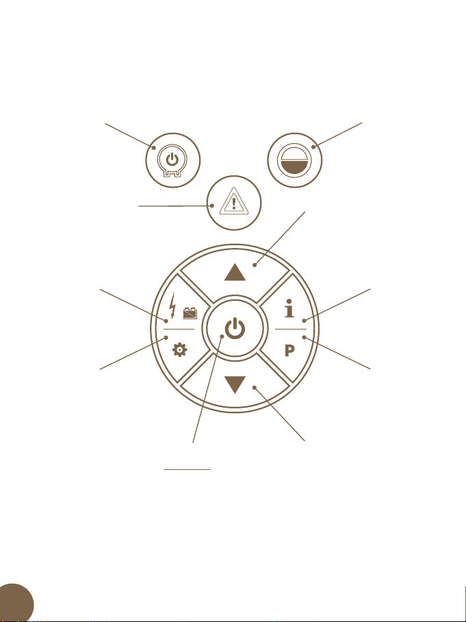
6. REMOTE CONTROLLER
6.1. Remote controller
fencee power DUO RF PDX and energy DUO RF EDX can be used for up to 10 km (with direct
visibility between the controller and the energiser). However, the maximum range and
accuracy are aected by a number of factors — weather, terrain,
vegetation, etc. In a densely forested, or built-up terrain the range
will be shorter - which is not due to a defect of the device,
but by the laws of physics and technical possibilities
(within the permitted European standards). Ensuring maximum
range and accuracy of the device: Check if the battery
in the controller is suciently charged. Hold the controller
as high as possible, the RF antenna must point up and be
almost perpendicular to the ground.
Anténa
Displej
Klávesnice

6
6.2. Display
Sound
alarm
Controller
battery
Signal
strength
Update
mode
Type of
device
Energizer
power
Energizer
number
Energizer
battery
Measured
unit
Measured
value
Alarm
signaling

7
Sound alarm
Controller alarm sound turned on/o. Can be changed in the settings.
Controller Battery
Current battery capacity in the controller.
Displays three states FULL 100% IHALF 50% IEMPTY
Signal strength
Indication of the quality of connection between the controller and the energizer.
Data Update Mode
Indicates the set data update mode.
Round arrow – automatic mode with a frequency of 1 minute.
Round arrow with letter i – mode with a frequency of 1 hour.
The mode setting aects the battery life in the controller.
Energizer power
Indicates the status of the energizer — ON 100% ION 50% IOFF
Energizer number
Number of the selected energizer. It is possible to assign up to 6 energizers
to one controller.
Energizer battery
Current battery capacity of the energizer.
Displays three states - FULL 100% IHALF 50% IEMPTY
Type of device
Icon indicating the type of the selected device.
When communicating with the energizer, the icon will ash.
Currently, only the G - energizer icon is used.
Measured value
The value measured by the energizer and sent to the controller.
Measured unit
Unit of the measured value. Here you can see kV - voltage of the output pulse,
or V - battery voltage of the energizer.
Alarm signaling
The symbol ashes when an alarm is triggered, see. page 12, together with the specic
alarm symbol.
8
6.3. Keypad
Down
arrow
Pairing
Up
arrow
Info
Settings
Controller
ON / OFF
Data
Selection
Alarm
Energizer
ON / OFF
Energizer
power
Step back

9
UP Arrow / DOWN Arrow (short press)
Selection of device. Change the values in the settings mode.
Data selection (short press)
Toggles the data displayed on the controller. You can display the pulse voltage
(kV) or the energizer battery voltage (V).
Settings (long press)
Switches the controller to the settings mode where you can set the
behaviour of the controller.
Settings (short press)
Switching individual items in the settings mode.
Turn on (short press)
Exit the current mode. Goes back from pairing mode, or from setup mode back
to the main screen.
Turn on (long press)
Turns the controller on or o.
Info (short press) - manual data update
Updates the information of the selected energizer.
Pairing (long press)
Switches the remote controller into the pairing mode.
Energizer ON / OFF (short press)
Turns the selected energizer on or o.
Energizer power (short press)
Switches energizer power (50% or 100%)
Alarm (short press)
A short press turns o the controller's beep.
Alarm (long press)
Long press clears the alarm notication.

10
7. CONTROL
7.1. Pairing
The energizer is controlled from the main screen.
Use the UP and DOWN arrows to select the desired energizer.
When the Energizer ON / OFF or Energizer Power button is pressed the controller
immediately sends the command to the energizer.
Pulse voltage, or battery voltage can be monitored on the display.
To switch battery or pulse information, press the Data Selection button.
To connect the energizer to the controller, it is necessary to perform“pairing “.
• Turn on the energizer, and then turn it o with one short press of the button. Then press the
button for longer time (> 5 seconds) until the status LED starts ashing fast. Now the energizer
is in pairing mode.
• Press the pairing button on the controller for a longer time.
The letter P appears on the display. Now the controller is in pairing mode.
• Use the UP and DOWN arrows to select the desired position number on which
you want to pair.
• Move the controller close to the energizer (up to 20 cm) and press the Pairing button .
• If everything went well, the controller is now paired with the energizer. The controller switches
back to the main screen and the energizer switches back to the OFF RF state.
• If the pairing process did not go through, perform it again.
• If you want to delete a position on the controller, perform pairing without an energizer.
• If the controller does not nd any energizer, it deletes the paired position.
• If you want to exit the pairing mode, press the red button ON.
• It is possible to pair up to 6 energizers to one controller — you can control 6 energizers
with one controller.
• It is possible to pair up to 3 controllers to one energizer — you can control one energizer
with 3 controllers.

11
7.2. Basic screen
To enter the settings mode, press (long) the Settings button .
There are currently 3 items available in the settings menu. To select the desired item, shortly
press the Settings button .
To change the settings of the selected item, press the UP or DOWN arrow.
To exit the setting mode, shortly press the red button ON.
Alarm sound (letter“A”)
Audio notication of the controller can be enabled or disabled. The setting is indicated
by the speaker icon.
Update mode (letter“U”)
Sets the data update interval.
Automatic mode updates the data every minute but has a higher power consumption.
Automatic mode updates the data every hour, saving battery.
Limit of the voltage of the fence
Pulse voltage limit on the fence can be set. If the voltage drops below the required limit,
an alarm is triggered.
You can update the current energizer data at any time outside the
interval by pressing the button on the controller.

12
8. ALARMS
If any problem occurs, an alarm is triggered. The alarm is indicated on the controller by a ashing
triangle icon with an exclamation mark. At the same time, the controller starts to beep.
Possible errors:
Low pulse voltage
The “kV” unit and the alarm icon are flashing.
Low battery voltage of the energizer
The energizer battery icon and the alarm icon are flashing.
No signal
On the main screen, the letter E, is displayed, the signal and alarm icon flashes.
General alarm
Only the alarm icon flashes. There may be more causes. One of them is a step change in the
resistance of the fence. In this case, the fence requires physical inspection.
Press any button on the controller to turn off the sound of the alarm.
The alarm sound can be disabled in the settings.
If the problem is solved (battery replacement, fence repair...), press
the Alarm button for a longer time and alarm notification will be removed.

13
Cause Fault removal
Nothing is visible on the display. Change the battery.
Take care about correct polarity.
There are blinking symbols on display
and no values are displayed.
No device is paired.
Add required energizer.
and one of the symbols ash on the
display.
This is a report of a specic alarm, see. page 12
9. POSSIBLE SOURCES OF PROBLEMS
10. GUARANTEE
In addition to a guarantee requested by law, we provide you with a guarantee in accordance with below
listed conditions:
• Guarantee period begins on the day of its purchase. Guarantee claims are acknowledged
explicitly pursuant to submission of bill or cash voucher. Guarantee repair is free of charge, or
we reserve the right to deliver a device of the same value.
• Guarantee is valid in case of correct use in accordance with the instructions for use. It expires
in case of interferences by unauthorized persons and in case of using spare parts of foreign
origin.
• All deciencies resulting from material defects or manufacturing defects shall be removed in
manufacturer´s discretion by repairing or free-of-charge replacement of the energizer.
• In case of delivering spare parts or repairing, original guarantee period is not prolonged.
• Guarantee period and address of guarantee provider can be found in attached instructions
for use of given type of energizer.
• Accumulators or batteries of any type, damages due to overvoltage (caused by lightning
among others) and damages due to spill-over of accumulator acid are not included in the
guarantee.
This device is provided with guarantee period of 3 years according to our conditions for
guarantee! Safety instructions, earthing, putting into operation, care of batteries and
accumulator, conditions for guarantee and possible fault sources can be found in attached
instructions for use!
14
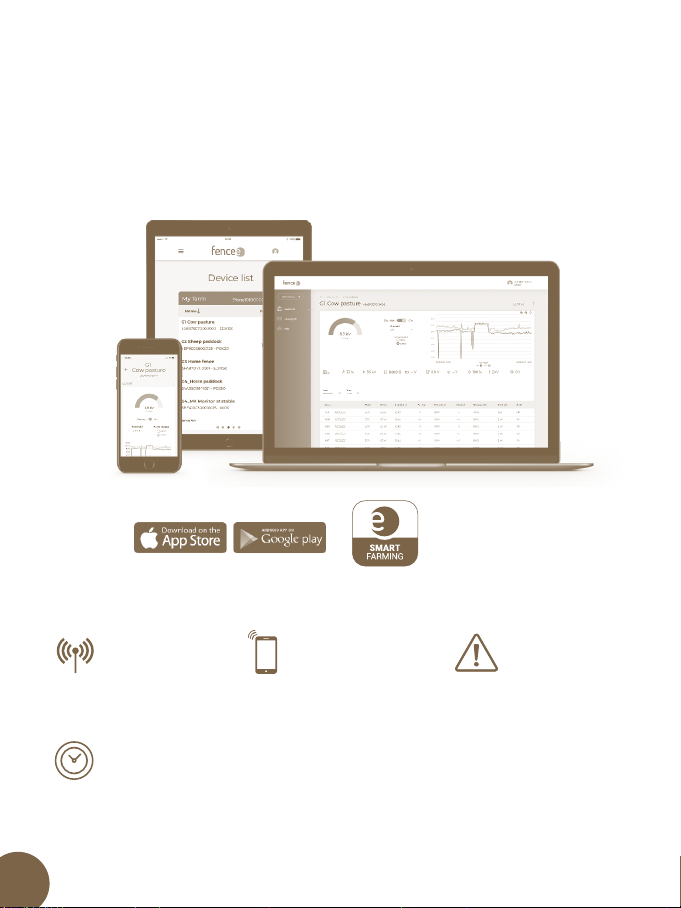
CURRENT
INFORMATION
Current online information
about all devices.
Control and monitor via
mobile application.
PHONE
CONTROL
ALARM
SIGNALIZATION
Problem notication
immediatelyin your
phone or e-mail.
TIME SAVING
Thanks to the remote control, you no longer have to visit your farm to check
the fencing. Everything is managed and controlled via your phone or the web.
Free to download
fencee Cloud
Control your fences from mobile phone with the fencee Cloud app

15
Control your fences from mobile phone with the fencee Cloud app
www.fenceefarm.com
FIND OUT MORE ABOUT THE SMART FARM SYSTEM
WATCH THE VIDEO
HOW THE SMART FARM SYSTEM WORKS

16
07062022
fencee.cz fenceeczech
www.fencee.eu
www.fenceefarm.com
www.fenceecloud.com
Electric fencing
VNT electronics s.r.o.
Dvorska 605, 563 01 Lanskroun
Czech Republic
info@fencee.eu
Stamp and signature of seller:
Table of contents
Popular Remote Control manuals by other brands


EU user manual")


Sony
Sony RM-AV2100B Operating Instructions (primary... operating instructions

Iconasys
Iconasys LED Studio Light 2.4GHz Wireless Remote... user guide

Jula
Jula Hard Heat 007590 operating instructions

OPTO 22
OPTO 22 SNAP-PAC-R1 user guide

Spektrum
Spektrum 5-Channel Full Range DSM2 2.4GHz Radio... user guide

Multiplex
Multiplex Royal Evo instructions