Fermax 850/25 User guide
MANUAL INSTALADOR
INSTALLER MANUAL
ESPAÑOL
ENGLISH
ELECTROCERRADURAS MOD. 850
ELECTRICALLY OPERATED LOCKS MOD. 850
85
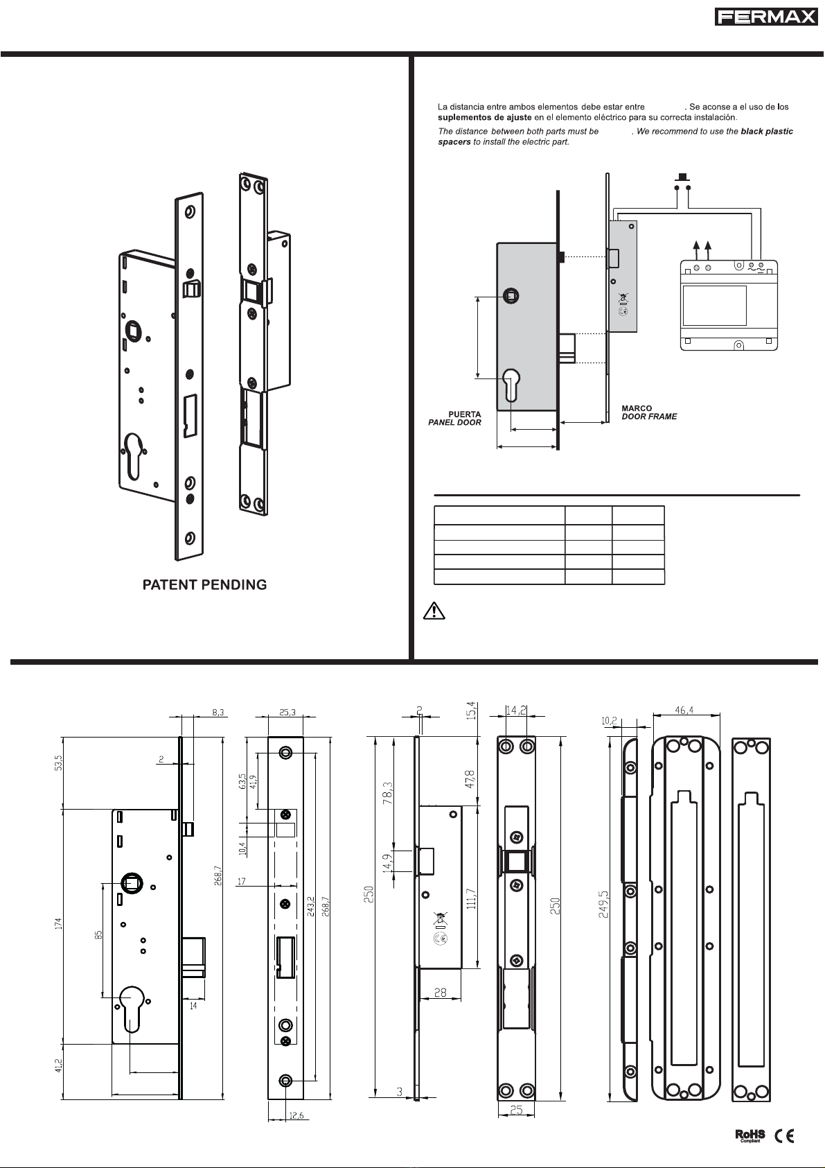
DETALLES DE INSTALACIÓN / INSTALLATION DETAILS.
TIPOS Y DIMENSIONES / BACKSET MODELS.
TIPOS A* C*
MOD.850/25 25 39
A*: Distancia en mm entre
el centro del cilindro y el
frente. / Backset in mm
30 44
35 49
50 64
Se recomienda el uso de esta cerradura en com inación con un cierra uertas
To be installed with an automatic door closer
j
MOD.850/30
MOD.850/35
MOD.850/50
PRIM 230VAC
97655 V09_11
ELECTROCERRADURAS MOD. 850 - ELECTRICALLY OPERATED LOCKS MOD. 850
MOD.850
ELEMENTO MECÁNICO / MECHANICAL PART ELEMENTO ELÉCTRICO / ELECTRIC PART SUPLEMENTOS DE AJUSTE
BLACK PLASTIC SPACERS
A *
B *
A
*
3 - 4 mm
PULSADOR
PUSH BUTTON
B
*
ELEMENTO MECÁNICO
MECHANICAL PART
ELEMENTO ELÉCTRICO
ELECTRIC PART
3-4 mm
3 y 4 mm

La distancia entre los dos frentes ha de ser la máxima posi le (entre 3 y 4mm) para que la presión ejercida por el picaporte so re la
ventana de latón esté controlada, además de que esto aumenta la vida del producto y permite que el cierre sea más suave.
De ido a que el funcionamiento está muy ajustado para a rir con solvencia, pero sin consumir en exceso se de e asegurar que la
cerradura reci e 12V estabilizados y el Am eraje especificado, por lo que se aconseja el uso de fuentes de alimentación y transformadores
que tengan potencia suficiente para la cerradura sin que so repasen los 12V.
La electrocerradura puede ser alimentada indistintamente en corriente alterna como en continua, pero se ha o servado un funcionamiento
más ó timo en alterna pues la variación en la corriente produce que pese a que exista una pequeña caida de tensión termine a riendo
en un plazo corto de tiempo.
Para funcionamientos de corriente continua instalamos un diodo para protejer la instalación de posi les so retensiones, si no se especifica
en el pedido y pretende utilizar éste tipo de corriente, aconsejamos la instalación de un diodo.
Para asegurar que la tensión que reci e el aparato es de 12V, la 850 puede complementarse con un Booster (elevador de voltaje), el
cual produce un aumento de la potencia entregada inicial garantizando el funcionamiento aun en edificios antiguos donde se producen
caídas de tensión significativas. Se ha de instalar en paralelo a la parte eléctrica y lo más cerca posi le a ésta para garantizar un
funcionamiento óptimo del sistema.
CARACTERÍSTICAS ELÉCTRICAS
1 V
-10ºC / 50ºC
Vdc -- 1350 mA
Vac -- 990 mA
12 Vac / Vdc
8 Ohmios
Ohmios
CONSEJOS DE INSTALACIÓN:
Es preferi le instalar el su lemento en forma de ram a
en la entrada de la parte eléctrica para facilitar la entrada
del picaporte, de éste modo se reduce la fuerza que se
ha de hacer al cerrar la puerta, la vi ración y el ruido,
además de que aumenta la vida del producto
sustancialmente pues el picaporte reci e un menor golpe
al cerrar.
La cerradura ha de instalarse centrada a la arte
eléctrica para que se pueda retraer la ca eza de palanca
li remente, si la puerta tiende a a rirse, se necesitará
limar los tetones antifricción de los laterales del
alojamiento de la palanca (en el agujero de la parte
eléctrica se ven dos tetones a cada lado, se de en limar
los más cercanos a la dirección de apertura y de dentro
hacia fuera, nunca de arri a a ajo) y además instalar
un cierrapuertas que centre las dos partes
automáticamente.
Tetones antifricción
Centrada a su
alojamiento
Dirección de limado
Dirección de apertura
Tetones a limar según
dirección de apertura
Ca eza de
palanca
Parte trasera de la
armadura del
cerradero eléctrico
ESPAÑOL

Preguntas más frecuentes:
Al abrir eléctricamente se escucha el "clack" carácterístico de la corriente contínua o el "zumbido y clack" si es en alterna,
ero no se abre.
La puerta está haciendo fuerza hacia afuera y ésto produce que el bulón roce con su alojamiento y no pueda retraerse por si solo
- La solución a éste pro lema es la de centrar la parte eléctrica respecto a la mecánica.
- En caso de no poder centrar las dos partes, se han de limar los tetones de la parte eléctrica dónde se aloja el ulón de la forma que
se especifica en los consejos de instalación, además de instalar un cierrapuertas que asegure que la puerta no hace fuerza constantemente
so re la cerradura.
He conectado la cerradura y no roduce ningún sonido ni abre eléctricamente.
La parte eléctrica está mal alojada, no recibe corriente o no recibe la necesaria
- Respetar la distancia entre la parte eléctrica y la mecánica de entre 3 y 4mm.
- Mirar que el picaporte de Nylon negro está centrado verticalmente con la ventana de latón. Una vez cerrada la puerta de en estar
totalmente en contacto.
- Asegurarse de que la cerradura reci e la potencia especificada. (Voltios x Amperios = W (Vatios))
- Revisar las conexiones por si hay cortocircuito.
- En lugar de instalar un pulsador se ha instalado un interruptor y al reci ir demasiado tiempo electricidad se ha quemado la o ina
interna.
La cerradura no abre inicialmente cuando se está haciendo fuerza en la uerta.
El bulón tiende a clavarse en los tetones de su alojamiento y no puede retraerse
- Instalar un cierrapuertas y limar los tetones del alojamiento de la parte electrica según se indica en los consejos de instalación para
que le resulte más sencillo retraerse al ulón.
El bulón de la arte mecánica actua de forma muy esada al actuar con la maneta y/o con la llave.
La instalación en la puerta no es correcta
- Revisar la cerradura en úsqueda de elementos extraños
- Agrandar el agujero de la puerta donde se aloja la cerradura para eliminar la presión so re las chapas.
- Revisar que la maneta de la puerta esté ien ajustada y su cuadradillo no esté ejerciendo fuerza en la mueca de la cerradura.
La cerradura se queda abierta cuando cierro la uerta ese a que he dejado de suministrarle electricidad.
Tenga en cuenta que la cerradura tiene la función automática, la cual produce que una vez cortada la corriente se queda a la espera
de que la persona abra la puerta y la vuelva a cerrar
Si éste roblema ocurre más de una vez.
La vibración de la puerta produce que el mecanismo se abra
- Respetar la distancia entre la parte eléctrica y la mecánica de entre 3 y 4mm, e instalar el suplemento con forma de rampa para un
cierre de la puerta más suave.
La cerradura no ermite que la uerta se cierre.
La cerradura está instalada al revés, la puerta está muy ajustada y/o el marco de la puerta donde golpea el picaporte tiene el acabado
en esquina
- Revise que la parte mecánica se ha instalado en la puerta y la parte eléctrica en el marco.
- Respetar la distancia entre la parte eléctrica y la mecánica de entre 3 y 4mm e instalar el suplemento con forma de rampa.
La ieza negra de la arte eléctrica que envuelve la ventana de latón reforzado se ha roto.
El vandalismo y una incorrecta instalación puede producir éste problema
- Desatornillar la armadura de la parte eléctrica y sacar la pieza de latón en forma de "T" y la "U" de Nylon negro. Limpiar y girar 180º
la pieza con forma de U y colocar la parte sin usar en la posición que se ha ía roto. Volver a colocar la pieza en su alojamiento de la
caja de forma que encajen los ejes de su ase en los agujeros de la caja, posteriormente la T y finalmente volver a atornillar la armadura.
RECUERDE, manipular las piezas interiores de cualquiera de las dos partes de la cerradura exceptuando las indicadas en éste manual,
produce la pérdida total de la garantía.
ESPAÑOL

ENGLISH
The distance etween the two faces has to e as great as possi le (between 3 and 4 mm) so that the pressure applied y the door handle
on the rass window is controlled. This also increases the lifetime of the product and allows for smoother closing.
Given that the operation is very tight for correct opening ut without excessive power consumption, you must ensure that the lock receives
a stable 12 v supply and the specified am erage. We thus recommend the use of power supplies and transformers that have sufficient
power for the lock without exceeding 12V.
The electrically-operated lock can e powered either using direct or alternating current. However, better o eration has een noted using
alternating current as the variation in current means that even if there is a slight power failure the lock opens in a short period of time.
For direct current operation we have installed a diode to protect the installation from possi le overvoltage. If you plan to use this type of
current and this is not specified in the order, then we recommend that you install a diode.
To ensure that the device receives a voltage of 12V the 850 model can e used with an additional booster. This produces an increase
in the initial power supplied, thus guaranteeing its operation even in older uildings where significant power failures may occur. The ooster
has to e installed in parallel and as close as possi le to the electrical section to ensure the optimal functioning of the system.
ELECTRICAL CHARACTERISTICS
1 V
-10ºC / 50ºC
Vdc -- 1350 mA
Vac -- 990 mA
12 Vac / Vdc
8 Ohmios
Ohmios
INSTALLATION GUIDE:
It is etter to install the ram sha ed accessory in the
entry to the electrical section to facilitate the entry of the
door handle, thus reducing the force required to close
the door, vi ration and noise, whilst also su stantially
increasing the door handles lifetime (as the door handle
receives less impact upon closing).
The lock has to e installed in the centre of the electrical
section so that the lever head can e freely retracted.
If the door tends to open then the friction reducing nipples
on the side of the level housing will have to e filed down
(in the gap of the electrical section you can see two
nipples on each side; the nipples closest to the opening
direction should e filed - in an outwards direction, never
downwards). In addition a door closer should e installed
to centre oth sections
automatically
.
Friction-reducing
nipples
Centred on
its housing
Filing direction
Opening direction
Nipples to e filed,
depending on the
opening direction
Lever head
Rear of the electrical
lock armature

FAQ:
When electrically o ened a characteristic clacking sound of the direct current is heard or a buzzing and clacking sound if
alternating current is used, but it does not o en.
The door is pressing outwards and this causes the bolt to rub against its housing, preventing it from sliding back
- Resolve this pro lem y centring the mechanical and electrical sections.
- If the two sections cannot e centred file the nipples in the electrical section where the olt is housed
as specified in the installation guide, also install a door closer to ensure that the door does not constantly pressure the lock.
The lock has been connected but it does not roduce any sound or o en electrically.
The electrical section is badly housed, it is not receiving current or it is not receiving the correct current
- Respect the distance of 3 to 4 mm etween the electrical and mechanical sections.
- Check that the lack nylon door handle is vertically centred on the rass window. When the door is closed these have to come into
complete contact with each other.
- Make sure that the lock receives the specified power supply.
(Volts
x
Amps
=
W
(Watts))
- Check the connections to see if there is a short circuit.
- A switch has een installed instead of a utton and given that it has received electricity for too long the internal coil has urned out.
The lock does not initially o en when the door is ushed.
The bolt tends to get stuck in the nipples of the housing and cannot be retracted
- Install a door closer and file the nipples in the housing of the electrical section, as indicated in the installation guide, so that the olt
can e retracted more easily.
The bolt in the mechanical section is very heavy when the lever and/or key is used to o erate it.
Incorrectly fitted in the door
- Check the lock to see if any foreign odies are present.
- Widen the hole in the door where the lock is housed to reduce pressure on the metal plates.
- Check that the door lever is tight and that its ox is not applying pressure to the lock face.
The lock remains o en when I close the door des ite the ower having been cut.
Bear in mind that the lock functions automatically, which means that if the current is cut it waits
for the person to open the door and close it once again
If this roblem occurs more than once.
Door vibration is causing the device to open
- Respect the distance of 3 to 4 mm etween the electrical and mechanical sections, and install the ramp-shaped accessory so that
the door closes more smoothly.
The lock revents the door from closing.
The lock has been installed upside down, the door is too tight and/or the door frame where the handle is impacting is
fitted in a corner
- Check that the mechanical section has een installed on the door and the electrical section on the frame.
- Respect the distance of 3 to 4 mm etween the electrical and mechanical sections, and install the ramp-shaped accessory.
The black element of the electrical section that covers the reinforced brass window has broken.
Vandalism or incorrect installation may cause this problem
- Unscrew the armature of the electrical section and remove the T-shaped rass part and the U-shaped lack nylon part. Clean and
turn 180º
and fit the unused part in the position where the reakage occurred. Replace the part in the ox housing so that the axes in its ase
are in line with the holes in the ox, then fit the T-shaped part and screw the armature into place once again.
REMEMBER, interfering with the inner parts of either of the two sections of the lock (except for those indicated in this guide) completely
invalidates the warrantee.
ENGLISH

This manual suits for next models
10
Table of contents
Languages:


