Ferno EZ Glide PowerTraxx 59T User manual

February 2013
Pub. No. 234-3479-02
Users’ Manual
59T EZ Glide® PowerTraxx™Evacuation Chair
Read this Manual and
Retain for Future Reference

2
© Ferno-Washington, Inc 234-3479-02
2
Chair Serial Number _________________________
Location: Rear of Seat Panel Frame
PowerTraxx™SerialNumber_________________________
Location: Inside Surface of Patient-Left Side Track
Disclaimer
This manual contains general instructions for the use, operation
and care of this product. The instructions are not all-inclusive. Safe
and proper use of this product is solely at the discretion of the
user. Safety information is included as a service to the user. All
other safety measures taken by the user should be within and under
consideration of applicable regulations. It is recommended that
training on the proper use of this product be provided before using
this product in an actual situation.
Retain this manual for future reference. Include it with the product
in the event of transfer to new users. Additional free copies are
available upon request from Customer Relations.
Proprietary Notice
The information disclosed in this manual is the property of Ferno-
Washington, Inc., Wilmington, Ohio, USA. Ferno-Washington, Inc.
reserves all patent rights, proprietary design rights, manufacturing
rights, reproduction use rights, and sales use rights thereto, and
to any article disclosed therein except to the extent those rights
are expressly granted to others or where not applicable to vendor
proprietary parts.
Limited Warranty Statement
The products sold by Ferno are covered by a limited warranty,
which is printed on all Ferno invoices. The complete terms and
conditions of the limited warranty, and the limitations of liability
and disclaimers, are also available upon request by calling Ferno at
1.800.733.3766 or 1.937.382.1451.
Ferno Technical Support
Customer service and product support are important aspects of each
Ferno product. Please have the product serial number available
when calling, and include it in all written communications. For
technical support questions:
Telephone (Toll-free) 1.800.733.3766 ext. 1010
Telephone 1.937.382.1451 ext. 1010
Email quality[email protected]
Ferno Customer Relations
For ordering assistance or general information:
CANADA AND THE U.S.A.
Telephone (Toll-free) 1.877.733.0911
Telephone 1.937.382.1451
Fax (Toll-free) 1.888.388.1349
Fax 1.937.382.1191
Internet www.ferno.com
ALL OTHER LOCATIONS
For assistance or information, please contact your Ferno
distributor. If you do not have a Ferno distributor, please contact
Ferno Customer Relations:
Ferno-Washington, Inc., 70 Weil Way
Wilmington, Ohio 45177-9371, U.S.A.
Telephone +1.937.382.1451
Fax +1.937.382.6569
Internet www.ferno.com
USERS’ MANUAL
To request additional free users’ manuals,
contact Ferno Customer Relations, your
Ferno distributor, or visit www.ferno.com.

3
© Ferno-Washington, Inc 234-3479-02 3
TABLE OF CONTENTS
Section Page Section Page
Ferno Technical Support_______________________ 2
Ferno Customer Relations _____________________ 2
1 - Safety Information __________________________ 4
1.1 Warning _______________________________ 4
1.2 Important ______________________________ 4
1.3 Tip ____________________________________ 4
1.4 Bloodborne Disease Notice ________________ 4
1.5 Recycling Notice_________________________ 4
1.6 Symbol Glossary _________________________ 5
1.7 Safety and Instruction Labels ______________ 6
2 - Operator Skills and Training __________________ 7
2.1 Skills __________________________________ 7
2.2 Training ________________________________ 7
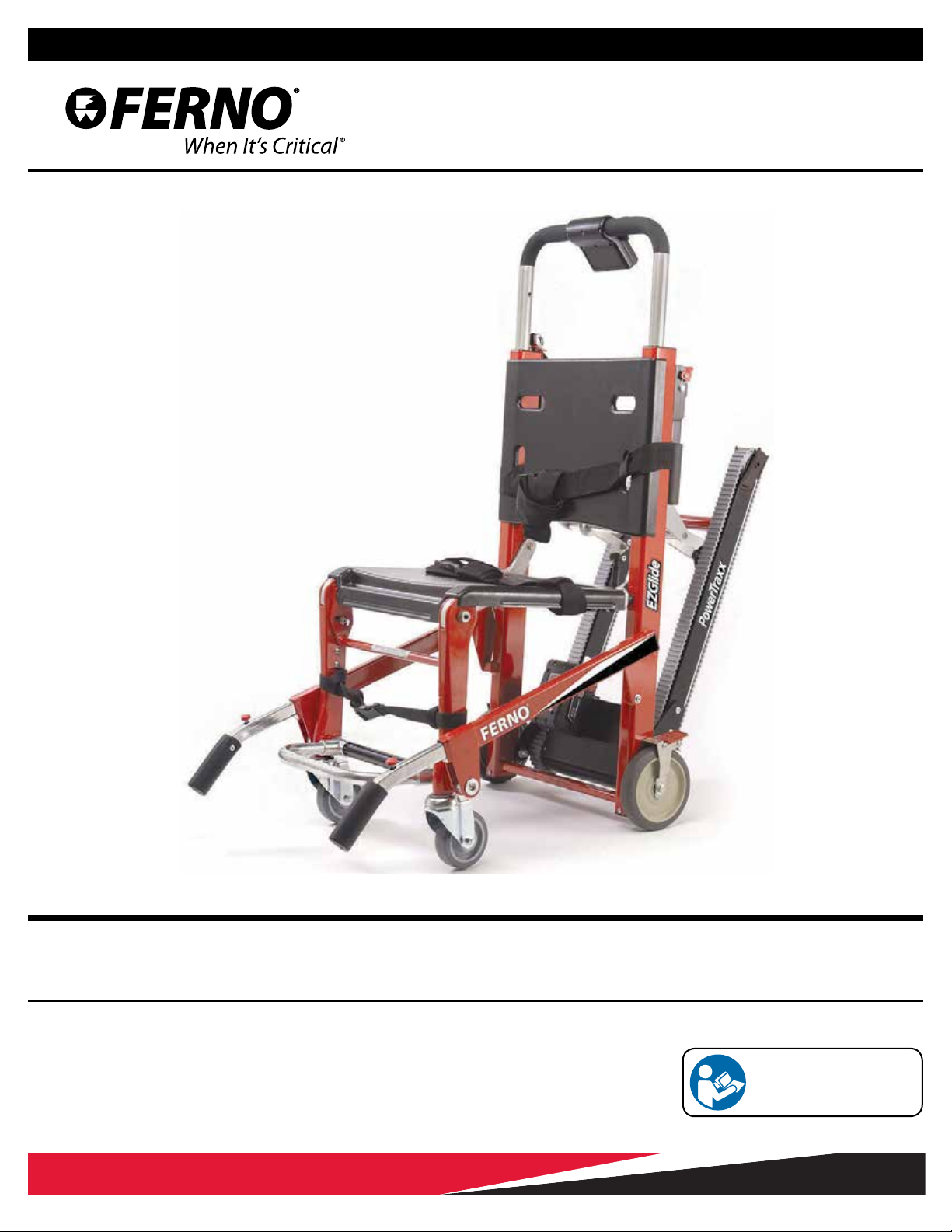
3 - About the Chair _____________________________ 7
3.1 Description _____________________________ 7
3.2 Compliance_____________________________ 7
3.3 Chair Features___________________________ 8
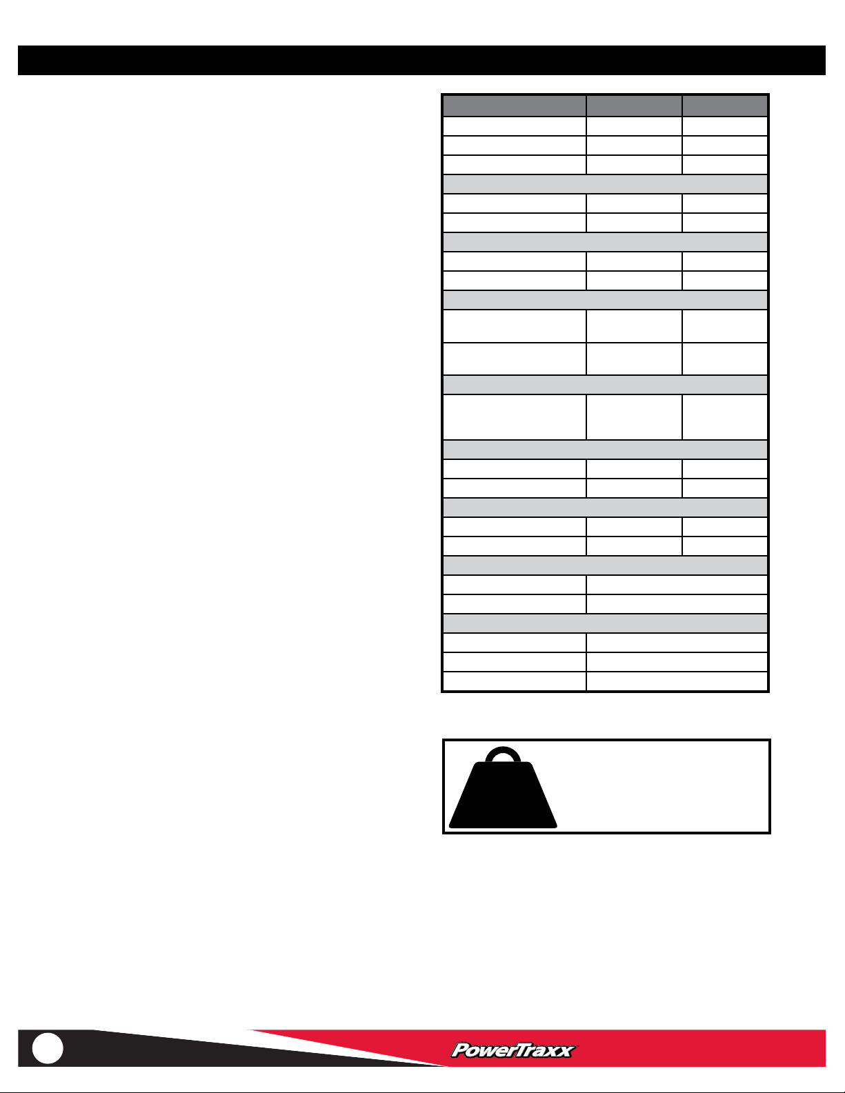
3.4 General Specications ____________________ 8
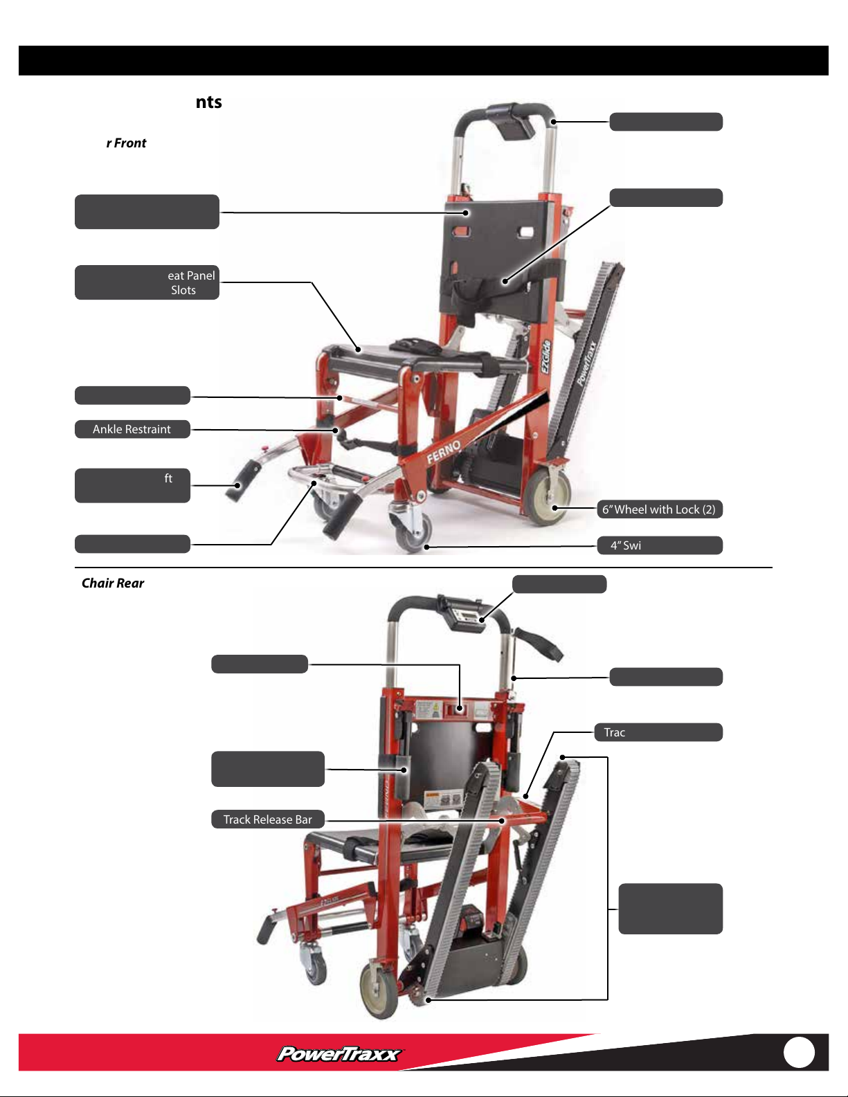
3.5 Components____________________________ 9
3.6 Items Supplied _________________________ 10
4 - Setup_____________________________________ 11
4.1 First-Time Setup ________________________ 11
4.2 Ankle Restraint _________________________ 11
4.3 Attaching Patient Restraints ______________ 12
4.4 Restraint Congurations _________________ 12
5 - Power System______________________________ 13
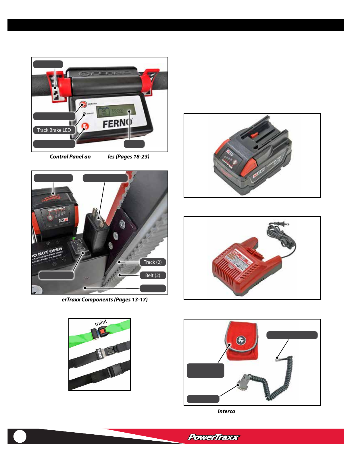
5.1 PowerTraxx Components_________________ 13
5.2 Main Battery ___________________________ 14
5.3 Attaching and Removing the Main Battery___ 15
5.4 Battery Charger ________________________ 16
5.5 Power Switch __________________________ 17
5.6 Paddles _______________________________ 17
6 - Control Panel ______________________________ 18
6.1 Control Panel Overview __________________ 18
6.2 Brake Button ___________________________ 19
6.3 Mode Button___________________________ 20
6.4 Display: Ascending (UP)
or Descending (Down) ___________________ 20
6.5 Display: Battery Status ___________________ 21
6.6 Display: Fault Codes _____________________ 22
7 - Chair Features _____________________________ 24
7.1 Folding and Unfolding the Chair ___________ 24
7.2 Track System___________________________ 25
7.3 Extending Lift Bar _______________________ 26
7.4 Telescoping Lift Handles _________________ 26
7.5 Footrest_______________________________ 27
7.6 Wheel Locks ___________________________ 27
8 - Using the Chair ____________________________ 28
8.1 Before Placing the Chair in Service _________ 28
8.2 General Guidelines for Use________________ 28
8.3 Transferring the Patient __________________ 29
8.4 Rolling the Chair________________________ 29
8.5 Transporting the Patient Down Stairs _______ 30
8.6 Pausing On the Stairs ____________________ 31
8.7 Transporting the Patient Up Stairs__________ 32
8.8 Using a Chair Without Power ______________ 34
8.9 Using Additional Help ___________________ 35
9 - Maintenance ______________________________ 36
9.1 Maintenance Schedule___________________ 36
9.2 Disinfecting/Cleaning Restraints ___________ 36
9.3 Disinfecting/Cleaning the Chair ___________ 36
9.4 Cleaning Tracks and Belts_________________ 36
9.5 Inspecting the Chair _____________________ 37
9.6 Control-Panel Batteries __________________ 37
9.7 Lubricating the Chair ____________________ 38
9.8 Do Not Lubricate Track System ____________ 38
9.9 Adjusting the Belt Tension ________________ 39
9.10 Removing and Attaching the ABS Panels ____ 40
9.11 Interconnect Cord ______________________ 41
9.12 Calibrating the Paddles __________________ 42
10 - Accessories_______________________________ 43
11 - Parts and Service__________________________ 44
11.1 U.S.A. and Canada_______________________ 44
11.2 Worldwide ____________________________ 44
11.3 Parts List ______________________________ 44
11.4 Parts Diagrams _________________________ 45
Training Record_______________________________ 46
Maintenance Record __________________________ 47

4
© Ferno-Washington, Inc 234-3479-02
4
1 SAFETY INFORMATION
Safety Information
1.1 Warning
Warning notices indicate a potentially hazardous situation
which, if not avoided, could result in injury or death.
WARNING
Untrained operators can cause injury or be injured.
Permit only trained personnel to operate the chair.
Improper use of the chair can cause injury. Use the chair
only for the purpose described in this manual.
Improperly attaching restraints can allow seat and back
panels to dislodge, resulting in injury. Restraints must
capture panel AND chair frame.
Improper charging can cause injury or damage. Use only
the Ferno-approved battery with the chair, and charge
only with the Ferno-approved battery charger.
Using the chair with the track system unlocked can
cause injury. Verify that the track system is locked before
transporting the patient.
Lubricating the track system can result in injury to the
patient and/or operators. Never lubricate the tracks or
belts.
Improper operation can cause injury. Operate the chair
only as described in this manual.
An unattended patient can be injured. Stay with the
patient at all times.
An unrestrained patient can fall o the chair and be
injured. Use restraints to secure the patient on the chair.
Helpers can cause injury or be injured. Maintain control
of the chair, operate the controls, and direct all helpers.
Improper maintenance can cause injury. Maintain the
chair only as described in this manual.
Attaching improper items to the chair can cause injury.
Use only Ferno-approved items on the chair.
Improper parts and service can cause injury. Use only
Ferno parts and Ferno-approved service on the chair.
Modifying the chair can cause injury and damage. Use the
chair only as designed by Ferno.
1.4 Bloodborne Disease Notice
To reduce the risk of exposure to bloodborne diseases such
as HIV-1 and hepatitis when using the chair, follow the
disinfecting and cleaning instructions in this manual.
WARNING
DO NOT OPEN MOTOR.
No user-serviceable parts inside.
Contact Ferno for service.
1.5 Recycling Notice
PROPERLY DISPOSE OF BATTERIES
Recycle batteries at the end of their service
life. Do not dispose of batteries with
municipal waste. Contact your government
for proper recycling.
The chair uses a rechargeable lithium-ion
battery to power the motorized PowerTraxx.
Two non-rechargeable type “AA” batteries are used in the
control panel.
U.S.A.
Recycling in the United States of America is regulated by
the Environmental Protection Agency (EPA). Contact your
state EPA for recycling information in your area.
WEEE DIRECTIVE E.U.
European Union directive 2002/96/EC Waste Electrical
and Electronic Equipment (WEEE) limits the disposal of
electrical and electronic equipment in landlls. Contact the
government in the country in which you reside for recycling
information.
Li-ion
1.3 Tip
Tips provide recommendations for easier use of the product.
Important
1.2 Important
Important notices emphasize important usage or maintenance
information. Failure to follow Important notices could result
in damage to the product or property damage.

5
© Ferno-Washington, Inc 234-3479-02 5
1.6 Symbol Glossary
The symbols dened below are used on the chair and/or in this users’ manual. Ferno uses symbols recognized by the International
Standards Organization (ISO), American National Standards Institute (ANSI) and the emergency medical services industry.
Safety Information
WEEE Directive:
Dispose of Batteries Properly
ASCEND DESCEND
Product meets European
Union Standards
Do Not
Lubricate
Lubricate
Read the Users’ Manual Chair Operation Requires
Two Trained Operators
2
Close PowerTraxx
General Warning of
Potential Injury
General Warning of Potential
Electric Shock
OFF ON
DC (Direct Current)
electricity
Do Not Pressure Wash
Open PowerTraxx AA Battery Charge Low
(Replace Control-Panel Batteries)
Do Not Step Here
Main Battery Full to
Moderate Charge
OK
MAIN
BATTERY
Main Battery
Charge is Low
CHECK
MAIN
BATTERY
Brake Engaged
(Belts Will Not Turn Freely)
Main Battery
Insufcient Charge
Load Limit
(Safe Working Load in
pounds, kilograms, stone)
500 lb
227 kg
35.7 st
Manufacturer Authorized Representative in the
European Community
Unlocked Locked
QR Code
(Access Online Material)

6
© Ferno-Washington, Inc 234-3479-02
6
Safety Information
1.7 Safety and Instruction Labels
Safety and instruction labels place important information from the users’manual on the chair. Read and follow label instructions.
Replace worn or damaged labels immediately. New labels are available from EMSAR, Ferno, or your Ferno distributor
(page 44). The labels illustrated below are afxed to the chair.
Safety Instruction: Do Not Open Motor
Instruction Labels:
Descend/Down; Ascend/Up
No Step Label:
Do Not Step On
Motor
Safe Use Guidelines
Instruction:
Adjusting Lift Bar
Risk of Injury: Do
Not Lubricate Tracks
Instruction:
Closing Tracks
Ferno Products are Protected by Patents Worldwide
Instruction: Folding/Unfolding the Chair
Instruction: Opening Tracks
Safety Instruction: Attaching Restraints

7
© Ferno-Washington, Inc 234-3479-02 7
3.2 Compliance
MEDICAL DEVICE DIRECTIVE
Ferno products meet the requirements of Medical Device
Directive 93/42/EEC as established by the European Union.
The chair meets the following standards:
● IEC 60601-1-2 (electrical and electromagnetic medical
equipment standards)
● IP 55 (Ingress Protection Rating; see Disinfecting/
Cleaning the Chair, page 36)
● EN 1865
3 ABOUT THE CHAIR
3.1 Description
The Ferno®Model 59T EZ Glide®Evacuation Chair with
PowerTraxx™(referred to as the chair in this manual) is an
emergency patient-handling device designed to transport a
seated patient up or down stairs and over at surfaces.
The chair is for professional use by a minimum of two
trained operators. A third person to “spot” may be required
by local protocols. Additional help may be required when
working with heavy patients.
The PowerTraxx option is a powered track system that
enables the operators to power the chair up or down
stairs instead of carrying it. The motor is powered by a
rechargeable 28 VDC battery (supplied).
WARNING
Improper use of the chair can cause injury. Use the
chair only for the purpose described in this manual.
Operator Skills and Training, About the Chair
2 OPERATOR SKILLS AND TRAINING
2.1 Skills
Operators using the chair need:
● a working knowledge of emergency patient-handling
procedures.
● the ability to assist the patient.
2.2 Training
Operator trainees need to:
● read and understand this manual.
● be trained on the use of the chair.
● practice with the chair before using it with a patient.
● record their training information. A sample training
record sheet is provided on page 46.
WARNING
Untrained operators can cause injury or be injured.
Permit only trained personnel to operate the chair.

8
© Ferno-Washington, Inc 234-3479-02
8
3.3 Chair Features
● PowerTraxx modular, motorized track system powers
the chair up and/or down stairs
● Paddle (2), controls track-belt motion
● Track brake (stops PowerTraxx motion when paddles
are not being pressed)
● Battery-charge indicators on main battery and display
● Power switch with light
● Kinetic Energy Regeneration System - descending in
manual mode will provide a small amount of charge to
the main battery
● Molded ABS seat and back panels
● Choice of color
● 5-position extending rear lift bar
● 5-position telescoping front lift handle (2)
● 6" rear locking wheel (2)
● 4" front swivel wheel (2)
● Folding footrest
● Ankle restraint
● Patient restraints (Options shown on page 10)
About the Chair
Load Limit
Inspect the chair if the load limit has
been exceeded (See Inspecting the
Chair, page 37).
500 lb
227 kg
35.7 st
3.4 General Specications
Specications for the chair are shown in the table at right.
Ferno reserves the right to change specications without
notice. For more information, contact Ferno Customer
Relations or your Ferno distributor (page 2). Ferno reserves
the right to change specications without notice.
Specication Imperial Metric
Load Limit 500 lb 227 kg
Load Limit (UK) 35.7 st
Weight* 56.6 lb 25.67 kg
Height
Maximum 63.5 1613 mm
Minimum 37.5 in 953 mm
Width
Overall 20.313 in 516 mm
Seat 16.5 in 419 mm
Depth (front to back)
Tracks closed,
Handles retracted
28.5 in 724 mm
Tracks Open,
Handles extended
51 in 1295 mm
Folded
Length x width x depth 37.5 in x
20.313 in x
10 in
953 mm x 516
mm x 254 mm
Wheels, Rear
Diameter 6 in 152 mm
Width 1.25 in 32 mm
Wheels, Front
Diameter 4 in 102 mm
Width 1.18 in 30 mm
Power
Main Battery 28VDC
Typical Charging Time About one hour
Miscellaneous
Chair Construction Rectangular aluminum
Seat/Back Panels ABS Plastic
Wheel Bearings Sealed/greaseless
*Weight is without restraints or accessories, but includes the battery

9
© Ferno-Washington, Inc 234-3479-02 9
About the Chair
Chair Rear
3.5 Components
Chair Front
Extending Lift Bar
Patient Restraint (2)
6”Wheel with Lock (2)
4” Swivel Wheel (2)
Telescoping Lift
Handle (2)
Folding Footrest
Ankle Restraint
Chair Lock Bar
Removable ABS Seat Panel
with Restraint Slots
Removable ABS Back
Panel with Restraint Slots
Track Release Bar
PowerTraxx
Components
(page 10)
Folding Lift Handle
(2, Optional)
IV Pole (Optional)
Control Panel
Track Closing Handle
Lift Bar Release

10
© Ferno-Washington, Inc 234-3479-02
10
Battery Charger (Page 16)
Main Battery (Pages 14-15)
Interconnect Cord (Page 41)
Telephone-Style Plug
Carrying Case
(Style May Vary)
Serial Plug
About the Chair
3.6 Items Supplied
● 28 VDC Lithium-ion rechargeable battery (1)
● 28 VDC Battery charger (1) Choice of:
○100-120 VAC (60 Hz North America; 50/60 Hz
Japan); UL Certied
○220-240 VAC, 50/60 Hz (Europe); CE Certied
● Interconnect cord with carrying case
● Users’ manual
Restraint Options (Contact Ferno for Details)
Model 430-P
Model 430
Coated Restraint
3.5 Components (Continued)
PowerTraxx Components (Pages 13-17)
Main Battery
Power Switch
Wireless Antenna
Control Panel and Paddles (Pages 18-23)
Paddle (2)
Display
Track Brake LED
Mode Button
Brake Button
Track (2)
Belt (2)
Motor

11
© Ferno-Washington, Inc 234-3479-02 11
1
4 SETUP
Setup
4.1 First-Time Setup
● Attach the restraints as described in this section.
● Inspect the chair (see Inspecting the Chair, page 37),
● Use the battery charger (supplied) to charge the main
battery (Figure 1). See Charging the Battery, page 16.
● Attach the fully-charged main battery to the chair. See
Attaching and Removing the Main Battery, page 15.
● Install the two AA batteries (supplied) in the control
panel (see Control-Panel Batteries, page 37). The
batteries are shipped in the carrying case with the
interconnect cord (see Components, page 10).
● Verify the PowerTraxx is functioning properly. If the
tension needs to be adjusted, see Adjusting the Track-
Belt Tension, page 39.
● Verify the paddles allow the user to press softly or
more rmly to control the speed of the PowerTraxx.
If the PowerTraxx runs constantly when power is
applied or if it immediately begins moving at full
speed, re-calibrate the paddles. See Calibrating the
Paddles, page 42.
● If all batteries are properly charged and installed but
the paddles do not function, the wireless connection
may have been lost. See Interconnect Cord, page 41.
4.2 Ankle Restraint
Use the ankle restraint to help keep the patient’s feet on the
footrest. Attach the two-piece ankle restraint to the front
legs of the chair. To attach the restraint:
1. Unbuckle the restraint to separate the straps.
2. Wrap a strap around one front leg of the chair and
thread the buckle through the loop, then pull the strap
tight around the chair leg (Figure 2).
3. Attach the remaining strap to the opposite front leg.
4. Buckle the restraint and adjust the length (Figure 3).
3
2

12
© Ferno-Washington, Inc 234-3479-02
12
Setup
4.3 Attaching Patient Restraints
Use patient restraints to help hold the patient on the chair.
Each restraint must capture both the aluminum chair frame
and the seat or back panel. Follow local protocols when
attaching restraints.
USING TWOPIECE RESTRAINTS
1. Feed the loop of a restraint strap through a slot in the
seat or back panel.
2. Wrap the strap around the aluminum chair frame and
feed the male or female buckle through the loop, then
pull the strap tight against the frame and panel.
3. Repeat Steps 1-2 for the other half of the restraint.
USING ONEPIECE RESTRAINTS
Note:Two-piece restraints are recommended.
1. To attach the seat-panel restraint, lay the restraint
across the top of the seat panel and feed the male and
female ends of the restraint down through the slots.
2. Wrap the restraint around the aluminum chair frame
on each side of the chair, capturing both the panel and
the frame (Figure 4).
3. Buckle the restraint and adjust the length.
4. Repeat Steps 1-3 to attach the back-panel restraint.
Important
Restraint rules (also follow your local protocols):
● Use a minimum of two restraints.
● One restraint must be secured across the chair seat
to help hold the patient on the chair.
● Each restraint or strap must capture the aluminum
chair frame and the plastic panel.
Horizontal
Conguration
Criss-Cross
Conguration
with Lap Belt
5
Straps Must Capture
Aluminum Frame and Panels
6
WARNING
Improperly attaching restraints can allow seat and
back panels to dislodge, resulting in injury. Restraints
must capture panels AND chair frame.
4.4 Restraint Congurations
Follow local protocols when conguring and using
restraints. Two possible congurations are described below.
HORIZONTAL CONFIGURATION
Use one restraint for the chest and one restraint for the lap
(Figure 5). Use additional restraints as needed.
1. Attach the chest straps through the vertical slots in the
back panel.
2. Attach the lap straps through the seat panel slots.
CRISSCROSS CONFIGURATION
Use two restraints for the torso and a third restraint for the
lap (Figure 6).
1. Attach one strap of a restraint through a horizontal slot
on the back panel of the chair.
2. Attach the mating strap of the same restraint through
the seat panel slot on the opposite side of the chair.
3. Repeat with the second restraint, attaching its straps to
opposite sides of the chair.
4. Attach the lap restraint through the seat-panel slots.
Capture Aluminum Frame and Panel at Each Side
4

13
© Ferno-Washington, Inc 234-3479-02 13
Power System
5 POWER SYSTEM
5.1 PowerTraxx Components
The PowerTraxx (Figure 7) consists of the following
components:
● CONTROL PANEL: The control panel is attached to
the lift bar. It allows the operator to control the speed
and direction of the belts, and monitor the batteries
and other aspects of the chair.
● PADDLES (2): The paddles are attached to the control
panel. The amount of pressure used by the operator to
press the paddle determines the speed of the belts.
● BELT (2): The belts engage the stairs. The motor
powers the belts. The user controls the speed and
direction using the paddles.
● MAIN BATTERY: The 28V battery attaches to the
motor and provides power. It is easily to remove,
charge, and reattach. See Main Battery, page 14.
● MOTOR: The motor is located between the tracks
at the base of the chair (Figure 7 and Figure 8). The
motor receives input from the paddles to control the
speed and direction of the belts. It also monitors other
aspects of the chair.
● ANTENNA: The antenna is mounted to the top of the
motor (Figure 8). It allows wireless communications
between the motor and control panel.
● POWER SWITCH: The switch is mounted to the top
of the motor and allows easy ON/OFF control of the
power system (See Power Switch, page 17).
● BRAKE (part of the motor): The brake allows the
belts to move only when a paddle is used. The brake
engages automatically when the system has power.
The operator may disengage the brake for non-
powered descent.
● SPEED LIMITER (part of the motor): If the system
loses power or the brake is disengaged, the belts are
free to rotate for non-powered descent. However, the
speed limiter retards the speed of the belts to improve
operator control for the descent.
WARNING
DO NOT OPEN MOTOR.
No user-serviceable parts inside. Contact
Ferno for service.
Power Switch
Main Battery
Motor
Control Panel;
Paddle (2)
Power Switch
and Antenna
Main Battery
Motor
Belt (2)
7
8
Antenna

14
© Ferno-Washington, Inc 234-3479-02
14
Important
Battery capacity can be aected if the battery is stored
for long periods below 0°F (-17°C) or over 150°F (66°C).
Power System
5.2 Main Battery
Note:The battery and charger instructions from Milwaukee
supersede those in this manual. For additional information, see
the manuals provided with these components.
The term “main battery” is used in this manual to describe the
Milwaukee®28-Volt DC, lithium-ion battery (Figure 9). The
control panel also uses batteries. See Control-Panel Batteries,
page 37.
The main battery powers the belts. It is sealed for resistance
to precipitation, dirt, body uids, cleaning solutions, etc. Use
only the Ferno-approved battery and battery charger. A battery
is provided with purchase of a chair or PowerTraxx retrot kit.
For additional batteries or chargers, see Accessories, page 43.
MAIN BATTERY INFORMATION
● Lithium-ion batteries have no “battery memory.” You do
not need to fully discharge the battery before recharging it.
● A typical fully-charged battery provides power to move
an average patient (250 pounds) up more than 200 stairs.
● Typical charging time is about one hour. Actual charging
time varies based on frequency of recharge, depth of
discharge, and battery age. If a battery becomes deeply
discharged, extend the charging time.
● Patient weight, extreme temperatures, and the combination
of using the chair to go up and/or down stairs affect the
amount of use available from each battery charge.
● The manufacturer’s recommended operating temper-
ature for the battery itself is 14°F to 120°F (-10°C to
49°C). The battery may be used in temperatures outside
this range. Battery capacity can be affected if the battery
is stored for long periods below 0°F (-17°C) or over
150°F (66°C).
● Recycle batteries at the end of their service life. Do not
dispose of batteries with municipal waste. See Recycling
Notice, page 4.
● Do not open the battery. There are no serviceable parts
inside the battery.
USING THE MAIN BATTERY
● The mounting slots (Figure 9) are compatible with
the motor and with the battery charger. See Attaching
and Removing the Main Battery, page 15, and Battery
Charger, page 16.
● Press the two red release buttons (Figure 9) to disconnect
the battery from the chair or battery charger.
● To check the charge of the main battery, press the test button
on the battery. See Battery-Charge Indicator, page 15.
● Store the battery ONLY in a cool, dry place. DO NOT
store where temperatures may exceed 120°F (50°C).
● If two batteries are available, keep the spare battery
charged and ready for use.
WARNING
Improper charging can cause injury or damage. Use
only the Ferno-approved battery with the chair, and
charge only with the Ferno-approved battery charger.
For additional information, see the Milwaukee®battery and battery-
charger manuals. Milwaukee®products are trademarks of the Milwaukee®
Electric Tool Corporation, Brookeld, Wisconsin, USA. Milwaukee®is a
subsidiary of Techtronic Industries Co. Ltd.
For warranty claims, take the charger or battery to an authorized
Milwaukee Service Center.
Mounting Slots
Release Button (2)
9
Battery Tips
To extend battery life, always turn the power
switch OFF when the chair is not in use.
Lithium-ion batteries have no “battery
memory.” You do not need to fully discharge
the battery before recharging it.

15
© Ferno-Washington, Inc 234-3479-02 15
5.3 Attaching and Removing
the Main Battery
To attach the main battery to the chair: Align the
mounting slots on the main battery (Figure 9, page 14)
with the mating ridges on the motor (Figure 11). Slide the
main battery onto the slots until it snaps into the locked
position (Figure 12). Verify that the main battery is securely
mounted on the motor before using the chair.
To remove the main battery from the chair: Press both
red release buttons on the main battery (Figure 9, page 14)
and slide it off the ridges on the motor.
MAINBATTERY CHARGE INDICATOR
The charge indicator on the main battery (Figure 10)
illuminates one to four red lights to indicate the charge
remaining in the battery (approximately 25% intervals).
Press the test button (Figure 10) and the light(s) will
illuminate briey. With a full charge, all four lights are
displayed. If the charge is lower than 10%, the rst light
ashes four times when the test button is pressed.
Extreme temperature (cold or hot), extreme patient weight,
and the age of the batteries affect how quickly the charge in
the batteries is used.
MAINBATTERY SHUTOFF
If the internal temperature of the battery becomes too
high, the main battery will shut off to protect itself, and all
powered chair motion stops.
To verify the battery has overheated, press the test button
on the battery. The battery will indicate it is overheated
by ashing the lights alternately. Allow the battery to cool
before use. When the battery is ready for use, pressing the
test button will show the remaining charge.
Power System
Important
If the main battery becomes overheated, it will shut o
to protect itself. Allow an overheated battery to cool
before use.
Test Button
Charge Indicator
Light (4)
10
Battery Mounting Slots
11
12
Battery Mounted
to Motor

16
© Ferno-Washington, Inc 234-3479-02
16
5.4 Battery Charger
Note:The battery and charger instructions from Milwaukee
supersede those in this manual. For additional information,
see the manuals provided with these components.
A battery charger suitable for use with your local power
supply is supplied with the chair (Figure 13):
● 100-120 VAC (60 Hz North America; 50/60 Hz Japan)
● 220-240 VAC, 50/60 Hz (Europe and other areas)
An adapter plug (not supplied) may be needed to adapt the
charger plug for the outlet.
Typical charging time is about one hour. If the batteries
are deeply discharged, extend the charging time. Actual
charging time may vary based on frequency of recharge,
depth of discharge, and age of batteries.
Store the charger ONLY in a cool, dry place. DO NOT store
where temperatures may exceed 120°F (50°C).
If the charger will be used inside an ambulance, it must
be securely mounted (mounting hardware not supplied).
A charger is included with purchase of a chair or
PowerTraxx retrot kit. For additional batteries or chargers,
see Accessories, page 43.
INDICATOR LIGHTS
The charger has one red and one green indicator light. The
lights work together to provide the following information:
● RED (Continuous): The battery is connected and is
being charged.
● GREEN (Continuous): Charging is complete.
● RED (Flashing): The temperature of the battery
is outside the proper charging range. Charging will
begin when the battery reaches the correct charging
temperature of 32°F-150°F (0°C-65°C).
● RED/GREEN (Flashing alternately): The battery is
damaged or faulty. Replace the battery.
CHARGING THE MAIN BATTERY
To attach a main battery for charging, align the slots on the
main battery (Figure 9, page 14) with the mating ridges
on the charger (Figure 13). Slide the main battery onto the
charger until it locks into position. Verify that the main
battery is properly connected and the indicator light on the
charger is lit.
To disconnect, press the two red release buttons on the main
battery (Figure 9, page 14) and slide it off the charger.
Power System
Important
If the battery charger will be used inside an ambulance,
it must be mounted. Mount the charger using the
mounting bracket built into the battery-charger.
(Mounting hardware is not supplied).
Important
Battery capacity can be aected if the battery is stored
for long periods below 0°F (-17°C) or over 150°F (66°C).
Mounting Ridges
13
Indicator Lights

17
© Ferno-Washington, Inc 234-3479-02 17
5.5 Power Switch
The rocker-style power switch is located on top of the
motor (Figure 14). It allows easy ON/OFF control of the
power system.
The switch is protected from liquids and dirt by a rubber
cover. You can press the switch through the cover. Do not
remove the rubber cover.
To use the chair:
1. Press (ON).
2. Tap a paddle (Figure 15) up or down to awaken the
wireless controller.
3. Allow a few seconds for the wireless connection to be
established. When the control panel and motor link,
the motor will emit three audible beeps.
4. Use the chair as instructed in this manual.
5. Press (OFF) to disengage the power.
Power System
5.6 Paddles
The paddles are afxed to the control panel on the extending
lift bar, where they are accessible to the operator’s hands.
The paddles are labeled with the symbol of a stairway and
an arrow for “descend/down” and “ascend/up” (Figure 15).
The amount of pressure used to press the paddle affects the
speed of the belts. This allows the operator to control the
speed of the chair on stairs.
To use a paddle:
1. Position your hands to comfortably grasp the
extending lift bar, with at least one paddle accessible
to your thumb.
2. Press the top or bottom of either paddle to operate the
powered track system.
For complete instructions, see Using the Chair, pages 28-35.
DESCEND
Paddle (2)
ASCEND 15
Power Switch
14
Power Light
Paddles
The amount of pressure used to press the
paddle aects the speed of the belts. This
allows the operator to control the speed of the
chair on stairs.
Battery Tips
To extend battery life, always turn the power
switch OFF when the chair is not in use.

18
© Ferno-Washington, Inc 234-3479-02
18
6 CONTROL PANEL
6.1 Control Panel Overview
The control-panel components are (Figure 16):
● Brake Button - The symbol on this button is a “Stop
Sign” with a slash through it .
● Indicator Light - The light is illuminated red, green,
or is not illuminated to provide feedback to the user.
● Mode Button - The symbol on this button is the Ferno
“FW” logo .
● Display - The liquid-crystal display provides informa-
tion about a variety of chair functions, including
battery charge, battery status, brake status, calibration
and setting information, and more.
SOFTWARE VERSIONS
The information displayed varies depending on the software
installed in the motor and control panel.
The software version is displayed briey during the
calibration procedure (see Calibrating the Paddles, page
42). Be aware that you will need to calibrate the paddles to
exit this mode.
WIRELESS CONNECTION
Each time the power switch is pressed ON, the motor must
make a wireless connection with the control panel.
1. Press the power switch . The motor will beep every
ve seconds until it locates and connects with
the control panel, or until you press .
2. Tap a paddle in either direction. The control panel
awakens and attempts to connect with the motor.
3. When the components link, the motor emits three
beeps. The display shows the standard screen
indicating the status of the Main Battery. If there is
sufcient power, the brake is engaged.
If the link fails, the control panel briey displays the
text, “MASTER not found!” (Figure 17). After this,
the control panel will go to sleep.
Control Panel
If the text,“MASTER not found!”is displayed, the motor
cannot locate the control panel. Do the following:
● Connect a charged main battery (page 15).
● Press the power switch (page 17).
● If these solutions don’t work, attach the
interconnect cord (page 41).
17
Paddle (2)
Display
Track Brake LED
Mode Button
Brake Button
16
Non-Wireless Connection
As an option, the interconnect cord (provided)
may be permanently connected to the control
panel and motor. In this state, the control
panel does not need to connect wirelessly to
the controller. See Interconnect Cord, page 41.

19
© Ferno-Washington, Inc 234-3479-02 19
6.2 Brake Button
The brake prevents the belts from moving unless a paddle is
pressed. By default, the brake is engaged when the system
has power. To disengage or re-engage the brake, press the
brake button on the control panel (Figure 18).
Disengage the brake to allow the belts to rotate without
power (for example, to descend stairs without using the
power system).
Depending on the version of the software, both the display
and indicator light will change to match the current state of
the brake. Refer to the images at right.
ORIGINAL SOFTWARE
● Brake engaged: The indicator light is off; the display
shows the word, “BRAKE” (Figure 18).
● Brake disengaged: The indicator light is red and the
display shows the word “IDLE” (Figure 20).
SOFTWARE V 1.5P5+
● Brake engaged: The indicator light is green; the
display shows the word “BRAKE”, and the brake
symbol is displayed (Figure 19).
● Brake disengaged: The indicator light is red; the
display shows the word “IDLE”. The brake symbol is
not displayed (Figure 20).
SPEED LIMITER
With or without power, an internal speed-limiting device
limits the speed of the belts as the chair descends stairs. Use
care and control the descent of a chair that is unpowered or
has the brake disengaged.
Control Panel
Brake Engaged, Original Software: The indicator
light is OFF and the display shows the word “BRAKE”
Brake Button
18
Brake Engaged, Software V1.5p5+: The indicator
light is green, the display shows the word “BRAKE”,
and the brake symbol is displayed in the lower-right
corner of the display.
Brake Symbol
19
Brake Disengaged, All Software Versions: The
indicator light is red and the display shows the word
“IDLE”. (For v1.5p5+, the brake symbol is not shown).
20
About the Brake
The brake is engaged ONLY when the system
has power. If the battery charge is depleted,
the brake will disengage. Use additional help
as needed.

20
© Ferno-Washington, Inc 234-3479-02
20
6.3 Mode Button
The mode button is the Ferno logo .
Press and hold for four seconds to show the chair status
on the display (Figure 21). The display will show the current
voltage and amperage used by the power system, plus the
revolutions per minute (RPM) of the motor.
Note:The RPM indicator tells only the speed of the motor,
not the belts.
The chair can be used normally while the status screen is
displayed. To return to the standard screen, press the mode
button briey.
Control Panel
6.4 Display: Ascending (UP)
or Descending (Down)
When a paddle is pressed, the display shows your choice of
direction by displaying the word “UP” or “DOWN” (Figure
22). The text is shown while the tracks are in motion. When
the paddle is released, the display returns to the standard
screen.
21
22
Mode Button
This manual suits for next models
3
Table of contents
Other Ferno Indoor Furnishing manuals
Popular Indoor Furnishing manuals by other brands

New Classic Furniture
New Classic Furniture RYLAND U5985-30P1 Assembly instructions

Dorel
Dorel NIGHTSTAND DL8417-7 instruction manual

Mäusbacher
Mäusbacher 0546/140-90 P1 Assembly instructions

Furniture FX
Furniture FX VANCOUVER Assembly instructions

Freedom
Freedom ALLY DESK 24595476 Assembly instructions

siena GARDEN
siena GARDEN Ponza 431.282 Assembly instruction

Core Products
Core Products CR912 Instruction leaflet

Songmics
Songmics VASAGLE LBC11V1 manual

StandCrafted
StandCrafted THE STANDCRAFTED DESK installation manual

Spectra
Spectra Hello Kitty KT3099 owner's manual

Trinity Basics
Trinity Basics TBTZ-0969 owner's manual

Coaster
Coaster 700882 Assembly instructions