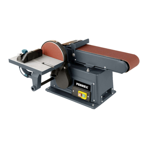
FERREX BTS920 User manual

AFTER SALES SUPPORT 10699
1300 855 831
MODEL:
BTS920
5
YEAR
WARRANTY
AU
Made in China
FERREX®is a registered trademark of ALDI Stores
DISTRIBUTED BY:
ALDI STORES
1 SARGENTS ROAD
MINCHINBURY NSW 2770
www.aldi.com.au
AU
ALDI guarantees that our exclusive brand products are developed to our
stringent quality specifications. If you are not entirely satisfied with this
product, please return it to the nearest ALDI store within 60 days from the
date of purchase, for a full refund or replacement, or take advantage of our
after sales support by calling the supplier’s Customer Service Hotline.
05/2021

User Manual
BELT & DISC SANDER 450W
BTS920

Contents
Dok./Rev.-Nr. 10699_20210226
Overview ..................................................................................... 3
Package contents/part list ......................................................... 6
Explanation of Symbols .............................................................. 7
Introduction ................................................................................ 9
Layout .........................................................................................10
Scope of delivery........................................................................10
Intended use ..............................................................................10
Safety regulations...................................................................... 11
Assembly ....................................................................................16
Operation....................................................................................17
After Use .................................................................................... 20
Technical data ............................................................................21
Storage and transport .............................................................. 22
Electrical connection................................................................. 22
Disposal and recycling .............................................................. 23
Troubleshooting........................................................................ 24
Warranty Details........................................................................ 25
Repair and Refurbished Goods or Parts Notice ....................... 26

3
2
9
3
11
1
1
1
2
3
4
4
56
6
7
7
8
8
9
9
10
10
1111 12.2
13
14
12 .1

4
4
7
613
5
10
4
1
6
613
7
1
7
7
8
8
A
9
14
B
10 11
C4

5
1313
E
F
14
9
G
15
H
11
16
II
17
1
3
12
7
8
D
9
C

56
Package contents/part
list
1Sanding Belt, 1x
2Belt adjustment knob, 1x
3Belt unlocking lever, 1x
4Tool rest, 1x
5ON- / OFF switch, 1x
6Clamping screw, 1x
7Table, 1x
8Mitre gauge, 1x
9Sanding disc, 1x
10 Allen screw with disc, 2x
11 Support screw,1 x
12.1 Dust outlet for sanding belt, 1x
12.2 Dust outlet for sanding disc, 1x
13 Washer, 1x
14 Allen key, 1x
15 Warranty card
16 Instruction manual


Kapitelüberschrift
7
Explanation of symbols
Explanation of Symbols
The use of symbols in this manual is intended to draw your attention to possible risks.
The safety symbols and the explanations that accompany them must be perfectly un-
derstood. The warnings in themselves do not remove the risks and cannot replace
correct actions for preventing accidents.
Before commissioning, read and observe the operating
instructions and safety instructions!
Wear safety goggles!
Wear hearing protection!
If dust builds up, wear respiratory protection!
Direction of sanding belt.
Made in China
Complies with the Australian norms and standards.
Warranty period.
Warranty class.
5
YEAR
WARRANTY

Kapitelüberschrift
8
Explanation of symbols
m Attention! These operating instructions provide places concerning
your safety which are marked with this indication.
m Caution! Failure to follow these instructions may cause light to
medium risk of injury.
m Warning! Failure to follow these instructions may cause danger to
life or danger of serious injuries!

9
Introduction
Congratulations on choosing to buy a FERREX®product.
All products brought to you by FERREX®are manufactured to the highest standards
of performance and safety, and as part of our philosophy of customer service and
satisfaction, are backed by our comprehensive 5 Year Warranty.
We hope you will enjoy using your purchase for many years to come.
Note:
According to the applicable product liability law the manufacturer of this device is
not liable for damages which arise on or in connection with this device in case of:
• improper handling,
• non-compliance with the instructions for use,
• repairs by third party, non-authorised skilled workers,
• installation and replacement of non-original spare parts,
• improper use.
Recommendations:
Read the entire text of the operating instructions prior to the assembly and operation
of the device.
These operating instructions are intended to make it easier for you to get familiar
with your device and utilise its intended possibilities of use.
The operating instructions contain important notes on how to work safely, properly
and economically with your machine and how to avoid dangers, save repair costs,
reduce downtime, and increase the reliability and working life of the machine.
In addition to the safety regulations contained herein, you must in any case comply
with the applicable regulations of your country with respect to the operation of the
machine.
Keep the operating instructions in a clear plastic folder to protect them from dirt and
humidity; store them near the machine. The instructions should be read and careful-
ly understood by each operator prior to using the machine. Only persons who have
been trained in the use of the machine and are aware of the related dangers and
risks should be allowed to use the machine. The local required minimum age must
be met.
In addition to the safety notes contained in these operating instructions and
any specific regulations in your country, the generally recognised technical
rules for the operation of identically constructed machines must be observe-
Introduction

10
Layout (Fig. 1)
1. Sanding belt
2. Belt adjustment knob
3. Belt unlocking lever
4. Tool rest
5. ON- / OFF switch
6. Clamping screw
7. Table
8. Mitre gauge
9. Sanding disc (Hook and loop)
10. 2x Allen screw with disc
11. Support screw
12.1 Dust outlet for sanding belt
12.2 Dust outlet for sanding disc
13. Washer
14. Allen key
Scope of delivery
Belt & Disc sander 1x
Sanding disc - 80 grid 1x
Sanding belt - 80 grid (pre-
mounted)
1x
Allen key 1x
Warranty card 1x
Instruction manual 1x
• Open the packaging and take out
the equipment with care.
• Remove the packaging material.
• Check that all listed contents are
present.
• Inspect the equipment and parts
for any damage. Please contact
the helpline if anything is missing.
• If possible, keep the packaging
until the end of the guarantee
period.
• Read the operating instructions
fully to familiarise yourself with
the tool prior to using it.
• Only use original accessories
and spare parts. Spare parts are
available by
contacting the helpline.
• Specify the part numbers when
you contact the helpline.
m ATTENTION!
The device and packaging materi-
als are not toys!
Children must not be allowed to
play with plastic bags, film and
small parts! There is a risk of swal-
lowing and suffocation!
Intended use
The belt & disc sander 450W is used
for sanding all types of wood, de-
pending on the size of the machine.
The machine meets the currently
valid EU machine directive.
• The manufacturer’s safety, oper-
ation and maintenance instruc-
tions as well as the technical data
given in the calibrations and
dimensions must be adhered to.
• Relevant accident prevention
regulations and other generally
recognized safety and technical
rules must also be adhered to.
• The machine may only be used,
maintained or repaired by
Layout/Scope of delivery/Intended use

11
trained persons who are familiar with the machine and have been informed about
the dangers. Unauthorized modifications of the machine exclude a liability of the
manufacturer for damages resulting from the modifications.
• The machine is intended for use only with original spare parts and original tools
from the producer.
• Any other use is considered to be not intended. The manufacturer excludes any
liability for resulting damages, the risk is exclusively borne by the user.
Please note that our equipment has not been designed for use in commercial, trade or
industrial applications. Our warranty will be voided if the equipment is used in commer-
cial, trade or industrial businesses or for equivalent purposes.
Safety regulations
m WARNING ! Read all safety warnings, instructions, illustrations and
specifications provided with this power tool. Failure to follow all in-
structions listed below may result in electric shock, fire and/or serious
injury.
Save all warnings and instructions for future reference.
The term “power tool” in the warnings refers to your mains-operated
(corded) power tool or battery-operated (cordless) power tool.
1) Work area safety
• Keep work area clean and well lit. Cluttered or dark areas invite acci-
dents.
• Do not operate power tools in explosive atmospheres, such as in the
presence of flammable liquids, gases or dust. Power tools create sparks
which may ignite the dust or fumes.
• Keep children and bystanders away while operating a power tool. Dis-
tractions can cause you to lose control.
2) Electrical safety
• Power tool plugs must match the outlet. Never modify the plug in any
way. Do not use any adapter plugs with earthed (grounded) power
tools. Unmodified plugs and matching outlets will reduce risk of elec-
Intended use/Safety regulations

12
tric shock.
• Avoid body contact with earthed or grounded surfaces, such as pipes,
radiators, ranges and refrigerators. There is an increased risk of electric
shock if your body is earthed or grounded.
• Do not expose power tools to rain or wet conditions. Water entering a
power tool will increase the risk of electric shock.
• Do not abuse the cord. Never use the cord for carrying, pulling or un-
plugging the power tool. Keep cord away from heat, oil, sharp edges or
moving parts. Damaged or entangled cords increase the risk of electric
shock.
• When operating a power tool outdoors, use an extension cord suitable
for outdoor use. Use of a cord suitable for outdoor use reduces the risk
of electric shock.
• Recommendation that the tool always be supplied via a residual cur-
rent device having a rated residual current of 30 mA or less.
3) Personal safety
• Stay alert, watch what you are doing and use common sense when
operating a power tool. Do not use a power tool while you are tired
or under the influence of drugs, alcohol or medication. A moment of
inattention while operating power tools may result in serious personal
injury.
• Use personal protective equipment. Always wear eye protection.
Protective equipment such as a dust mask, non-skid safety shoes, hard
hat or hearing protection used for appropriate conditions will reduce
personal injuries.
• Prevent unintentional starting. Ensure the switch is in the off-position
before connecting to power source and/or battery pack, picking up or
carrying the tool. Carrying power tools with your finger on the switch
or energising power tools that have the switch on invites accidents.
• Remove any adjusting key or wrench before turning the power tool on.
A wrench or a key left attached to a rotating part of the power tool may
result in personal injury.
Safety regulations

13
•Do not overreach. Keep proper footing and balance at all times. This
enables better control of the power tool in unexpected situations.
•Dress properly. Do not wear loose clothing or jewellery. Keep your
hair and clothing away from moving parts. Loose clothes, jewellery
or long hair can be caught in moving parts.
•If devices are provided for the connection of dust extraction and
collection facilities, ensure these are connected and properly used.
Use of dust collection can reduce dust-related hazards.
•Do not let familiarity gained from frequent use of power tools allow
you to become complacent and ignore power tool safety principles.
A careless action can cause severe injury within a fraction of a sec-
ond.
4) Power tool use and care
•Do not force the power tool. Use the correct power tool for your ap-
plication. The correct power tool will do the job better and safer at
the rate for which it was designed.
•Do not use the power tool if the switch does not turn it on and off.
Any power tool that cannot be controlled with the switch is danger-
ous and must be repaired.
•Disconnect the plug from the power source and/or remove the
battery pack, if detachable, from the power tool before making any
adjustments, changing parts of insert tools, or storing power tools.
Such preventive safety measures reduce the risk of starting the
power tool accidentally.
•Store idle power tools out of the reach of children and do not al-
low persons unfamiliar with the power tool or these instructions to
operate the power tool. Power tools are dangerous in the hands of
untrained users.
•Maintain power tools and insert tools. Check for misalignment or
binding of moving parts, breakage of parts and any other condi-
tion that may affect the power tool’s operation. If damaged, have
the power tool repaired before use. Many accidents are caused by
poorly maintained power tools.
Safety regulations

14
•Keep cutting tools sharp and clean. Properly maintained cutting
tools with sharp cutting edges are less likely to bind and are easier
to control.
• Use the power tool, accessories and tool bits etc. in accordance with
these instructions, taking into account the working conditions and the
work to be performed. Use of the power tool for operations different
from those intended could result in a hazardous situation.
• Keep handles and grasping surfaces dry, clean and free from oil and
grease. Slippery handles and grasping surfaces do not allow for safe
handling and control of the tool in unexpected situations.
5) Service
• Have your power tool serviced by a qualified repair person using only
identical replacement parts. This will ensure that the safety of the pow-
er tool is maintained.
• Warning! This electric tool generates an electromagnetic field during
operation. This field can impair active or passive medical implants un-
der certain conditions. In order to prevent the risk of serious or deadly
injuries, we recommend that persons with medical implants consult
with their physician and the manufacturer of the medical implant prior
to operating the electric tool.
• Additional safety rules for the belt and disc sanding machine
• Warning: Do not use your machine until it is completely assembled and
installed according to the instructions.
• If you are not familiar with the operation of the sanding machine, ask
the head of the department, your teacher, or any other qualified per-
son.
• Attention: This machine has only been designed for sanding wood or
similar materials. The sanding of other materials can cause fire, injuries,
or damage the product.
• Always wear safety goggles.
• This machine may only be operated indoors.
• Important: Mount and use the machine on a horizontal surface. A
non-horizontal surface can damage the motor.
Safety regulations

15
• If the machine tends to tilt or walk (especially when sanding long and
heavy panels), it must be fastened to a solid surface of sufficient carry-
ing force.
• Make sure the sanding belt runs in the correct direction – see arrows at
the back of the belt.
• Make sure the sanding belt is running correctly so that it cannot come
off the drive pulleys.
• Make sure the sanding belt is not twisted or loose.
• Firmly hold the workpiece when sanding.
• Always use the fence when using the sanding machine in horizontal
position.
• Always hold the workpiece firmly to the table when using the sanding
disc.
• Always hold the workpiece to the side of the sanding disc running
downwards, in order to maintain the workpiece pressed to the table.
By using the upward-running side of the sanding disc, the workpiece
could be ejected and cause injury to persons.
• Always keep a minimum distance of about 1.5 mm or less between the
table or fence and the sanding belt or disc.
• Do not wear gloves. Do not hold the workpiece with a cloth during
sanding.
• Use sanding belt or disc of the correct grit corresponding with the
wood.
• Never sand workpieces too small to be held safely.
• Avoid awkward hand positions where a sudden slip could cause your
hand to touch the sanding belt or disc.
• When sanding a large piece of material, provide an additional support
at table height.
• Never sand an unsupported workpiece. Secure the workpiece with the
table or the fence. Exceptions are the sanding of curved workpieces on
the outside of the sanding disc.
• Always clear the table, fence or sanding belt of scraps or other objects,
before turning the machine on.
• Do not perform any layout assembly or set-up work on the table while
the sanding machine is in operation.
Safety regulations

16
• Switch the machine off and pull the power plug from the socket when
fitting or removing accessories.
• Never leave the working area of the sanding machine while the tool is
running, or as long as it has not come to an absolute standstill.
Residual risks
The machine has been built using modern technology and in accordance
with recognized safety rules.
Some hazards, however, may still remain.
• The grinding wheel poses a danger of injury to fingers and hands by
improper feeding or placement of tools.
• Danger of injury from thrown tools due to improper holding or feed-
ing.
• The use of incorrect or damaged mains cables can lead to electrical
injuries.
• Although having regarded all considerable rules there may still remain
not obvious remaining hazrds.
• Minimize remaining hazards by following the instructions in ”Safe-
ty regulations”, ”Use only as authorized” and in the entire operating
manual.
Assembly
Do not connect to power supply until assembly is complete. Failure to comply could
result in accidental starting and possible serious injury.
Mounting of the sanding disc (Fig. 2)
Attach the sanding disc (9) in the middle of the hook and loop sanding pad at the
machine.
Mounting of support screw (Fig. 3)
Screw the support screw (11) into the housing of the sanding belt (1) by hand and
secure the nut of the support screw (11) with an open-end key (size 16 mm / not scope of
delivery).
This machine has two options for mounting the table (7).
Option 1:
1. Put the table (7) into the slot near by the sanding disc (9) and fix it with the clamping
screw (6) and washer (13). (Fig. 4)
Safety regulations/Assembly

17
2. Attach the tool rest (4) to the housing of the sanding belt (1) and secure it with the allen
screw with disc (10) and the allen key (14). (Fig. 5)
3. The maximum distance between sanding belt (1) and tool rest (4) must be 1.6mm.
Option 2:
1. Remove the tool rest (4) from the sanding belt housing. (Fig. 5)
2. Put the table (7) into the slot at the sanding belt housing and secure it with the
clamping screw (6) and washer (13). (Fig. 6)
Miter gauge mounting (Fig. 7)
Push the miter gauge (8) into the slot of the table (7).
Mounting machine to a work bench (Fig. 8)
It is necessary to secure the machine to a workbench or other stable surface before
the first use. When mounting the machine to a workbench, holes should be drilled
through the supporting surface of the workbench.
1. Mark holes on workbench where the machine is to be mounted using the holes
(A) in the base as a template for hole pattern.
2. Drill holes through workbench.
3. Place the machine on the workbench aligning holes in the base with holes
drilled in the workbench.
4. Insert bolts (not included) and tighten securely with lock washers and allen
nuts (not included).
Note:
All bolts should be inserted from the top. Install the lock washers and allen nuts
from the underside of the workbench.
Dust collection (Fig. 1)
Make sure that always a dust collector is connected to the dust outlet (12.1 / 12.2) at
the desired working position.
Operation
mWARNING!: Before performing any adjustment, make sure the machine is
unplugged from the power supply and the machine is switched OFF. Failure to
heed this warning could result in serious personal injury.
Adjusting the sanding belt tracking (Fig. 1)
• Plug in the machine.
To check sanding belt tracking:
Assembly/Operation

18
• Turn the ON-/ OFF switch (5) ON and then immediately turn it OFF. If the sanding
belt (1) tends to slide off the idler drum or drive drum, the sanding belt (1) is not
tracking properly.
To adjust sanding belt tracking:
1. Turn the belt adjustment knob (2) clockwise to adjust the sanding belt (1) to the
left direction.
2. Turn the belt adjustment knob (2) anticlockwise to adjust the sanding belt (1) to
the right direction.
3. Turn the ON-/OFF switch (5) ON and then immediately OFF again, noting belt
movement. Readjust the belt adjustment knob (2) if necessary.
Angle adjustment of the sanding belt housing (Fig. 9/10)
Your belt & disc sander can sand both vertically and horizontally. Depending on the
workpiece, the work support can be used with either the horizontal or vertical sand-
ing operation.
1. Loosen the screw (B) with the allen key (14).
2. Adjust the sanding belt housing in the desired position.
3. Tighten the screw (B) again.
Bevel sanding (Fig. 1/6)
The table (7) can be tilted from 0° to 45° for bevel sanding. To tilt the table (7):
1. The table (7) must be mounted at the sanding disc side or sanding belt side.
2. Loosen the clamping screw (6) by turning it anticlockwise.
3. Set the table (7) to desired angle.
4. Tighten the clamping screw (6) by turning it clockwise.
Switching ON/OFF (Fig. 1)
• Press the green button to switch the machine ON.
• Press the red button to switch the machine OFF.
mWARNING!:
Do not touch the sanding disc (9) or the sanding belt (1) while switching ON/
OFF. Risk of injury!
Surface sanding with the sanding belt (Fig. 11)
1. Hold the workpiece (C) firmly, keeping fingers away from the sanding belt.
2. Keep the end pressed firmly against the tool rest (4) moving work evenly across
the sanding belt.
Operation
Table of contents
Other FERREX Sander manuals
