Ferroli BLUEHELIX B 35 Troubleshooting guide

BLUEHELIX B 35
IT
ISTRUZIONE PER L’USO L'INSTALLAZIONE E LA MANUTENZIONE
ES
INSTRUCCIONES DE USO, INSTALACIÓN Y MANTENIMIENTO
TR
KULLANMA, KURULUM VE BAKøM TALIMATLAR
ø
EN
INSTRUCTIONS FOR USE, INSTALLATION AND MAINTENANCE
FR
INSTRUCTIONS D'UTILISATION, D'INSTALLATION ET D'ENTRETIEN
RU
ɊɍɄɈȼɈȾɋɌȼɈ ɉɈ ɗɄɋɉɅɍȺɌȺɐɂɂ, ɆɈɇɌȺɀɍ ɂɌȿɏɈȻɋɅɍɀɂȼȺɇɂɘ
U.
ȱɇɋɌɊɍɄɐȱə ɁȿɄɋɉɅɍȺɌȺɐȱȲ, ɆɈɇɌȺɀɍ ɌȺ ɈȻɋɅɍȽɈȼɍȼȺɇɇə

EN
1. GENERAL WARNINGS
&DUHIXOO\UHDGDQGIROORZWKHLQVWUXFWLRQVFRQWDLQHGLQWKLVLQVWUXFWLRQERRNOHW
$IWHUERLOHULQVWDOODWLRQLQIRUP WKH XVHU UHJDUGLQJ LWV RSHUDWLRQ DQG JLYH KLP WKLV
PDQXDOZKLFKLVDQLQWHJUDODQGHVVHQWLDOSDUWRIWKHSURGXFWDQGPXVWEHNHSWZLWK
FDUHIRUIXWXUHUHIHUHQFH
,QVWDOODWLRQDQGPDLQWHQDQFHPXVWEHFDUULHGRXWE\SURIHVVLRQDOO\TXDOLILHGSHUVRQ
QHOLQFRPSOLDQFHZLWKWKHFXUUHQWUHJXODWLRQVDQGDFFRUGLQJWRWKHPDQXIDFWXUHUV
LQVWUXFWLRQV'RQRWFDUU\RXWDQ\RSHUDWLRQRQWKHVHDOHGFRQWUROSDUWV
,QFRUUHFWLQVWDOODWLRQRULQDGHTXDWHPDLQWHQDQFHFDQUHVXOWLQGDPDJHRULQMXU\7KH
0DQXIDFWXUHUGHFOLQHVDQ\OLDELOLW\IRUGDPDJHGXHWRHUURUVLQLQVWDOODWLRQDQGXVH
RUIDLOXUHWRIROORZWKHLQVWUXFWLRQV
%HIRUHFDUU\LQJRXWDQ\FOHDQLQJRUPDLQWHQDQFHRSHUDWLRQGLVFRQQHFWWKHXQLWIURP
WKHHOHFWULFDOSRZHUVXSSO\XVLQJWKHVZLWFKDQGRUWKHVSHFLDOFXWRIIGHYLFHV
,QFDVHRIDIDXOWDQGRUSRRURSHUDWLRQGHDFWLYDWHWKHXQLWDQGGRQRWWU\WRUHSDLU
LW RU GLUHFWO\ LQWHUYHQH &RQWDFW SURIHVVLRQDOO\ TXDOLILHG SHUVRQQHO $Q\ UHSDLUUH
SODFHPHQWRIWKHSURGXFWVPXVWRQO\EHFDUULHGRXWE\TXDOLILHGSHUVRQQHOXVLQJRULJ
LQDOUHSODFHPHQWSDUWV)DLOXUHWRFRPSO\ZLWKWKHDERYHFRXOGDIIHFWWKHVDIHW\RI
WKHXQLW
7KLVXQLWPXVWRQO\EHXVHGIRULWVLQWHQGHGSXUSRVH$Q\RWKHUXVHLVGHHPHGLP
SURSHUDQGWKHUHIRUHKD]DUGRXV
7KH SDFNLQJ PDWHULDOV DUH SRWHQWLDOO\ KD]DUGRXV DQG PXVW QRW EH OHIW ZLWKLQ WKH
UHDFKRIFKLOGUHQ
7KHXQLWPXVWQRWEHXVHGE\SHRSOHLQFOXGLQJFKLOGUHQZLWKOLPLWHGSK\VLFDOVHQ
VRU\RUPHQWDODELOLWLHVRUZLWKRXWH[SHULHQFHDQGNQRZOHGJHRILWXQOHVVLQVWUXFWHG
RUVXSHUYLVHGLQLWVXVHE\VRPHRQHUHVSRQVLEOHIRUWKHLUVDIHW\
7KHXQLWDQGLWVDFFHVVRULHVPXVWEHDSSURSULDWHO\GLVSRVHGRILQFRPSOLDQFHZLWK
WKHFXUUHQWUHJXODWLRQV
7KHLPDJHVJLYHQLQWKLVPDQXDODUHDVLPSOLILHGUHSUHVHQWDWLRQRIWKHSURGXFW,Q
WKLVUHSUHVHQWDWLRQWKHUHPD\EHVOLJKWDQGLQVLJQLILFDQWGLIIHUHQFHVZLWKUHVSHFWWR
WKHSURGXFWVXSSOLHG
2. OPERATING INSTRUCTIONS
2.1 Introduction
'HDU&XVWRPHU
BLUEHELIX B 35LVDKLJKHIILFLHQF\ORZHPLVVLRQVpremix condensingKHDWJHQHUD
WRUZLWKheat exchanger in steelDQGLQFRUSRUDWHG'+:SURGXFWLRQUXQQLQJRQQDWXUDO
JDVRU/3*DQGHTXLSSHGZLWKDPLFURSURFHVVRUFRQWUROV\VWHP
7KHVHDOHGFKDPEHUXQLWLVVXLWDEOHIRULQGRRULQVWDOODWLRQRURXWGRRUVLQDpartially pro-
tected placeDFFRUGLQJWR(1$ZLWKWHPSHUDWXUHVWR&&ZLWKRSWLRQDO
DQWLIUHH]HNLW
AThe boiler is arranged for connection to an external hot water tank (op-
tional). In this manual, all the functions regarding DHW production are ac-
tive only with the optional hot water tank connected as indicated in
VHF
2.2 Control panel
fig. 1 - Control panel
Panel - legend fig. 1
1'+:WHPSHUDWXUHVHWWLQJGHFUHDVHEXWWRQ
2'+:WHPSHUDWXUHVHWWLQJLQFUHDVHEXWWRQ
3+HDWLQJV\VWHPWHPSHUDWXUHVHWWLQJGHFUHDVHEXWWRQ
4+HDWLQJV\VWHPWHPSHUDWXUHVHWWLQJLQFUHDVHEXWWRQ
5'LVSOD\
66OLGLQJ7HPSHUDWXUH0HQX6XPPHU:LQWHUPRGHVHOHFWLRQ5HVHWEXWWRQ
78QLW2Q2II(FRQRP\&RPIRUWPRGHVHOHFWLRQEXWWRQ
8'+:V\PERO
9'+:PRGH
10 6XPPHUPRGH
11 0XOWLIXQFWLRQIODVKLQJGXULQJH[FKDQJHUSURWHFWLRQIXQFWLRQ
12 (FR(FRQRP\PRGH
13 +HDWLQJ
14 +HDWLQJV\PERO
15 %XUQHUOLWDQGDFWXDOSRZHUOHYHOIODVKLQJGXULQJIODPHSURWHFWLRQIXQFWLRQ
16 6HUYLFH7RROFRQQHFWLRQ
17 :DWHUJDXJH
Indication during operation
Heating
$KHDWLQJGHPDQGJHQHUDWHGE\WKH5RRP7KHUPRVWDWRU5HPRWH7LPHU&RQWUROLVLQ
GLFDWHGE\IODVKLQJRIWKHKRWDLUDERYHWKHUDGLDWRURQWKHGLVSOD\
7KHGLVSOD\GHWDLOILJ VKRZVWKHDFWXDOKHDWLQJGHOLYHU\WHPSHUDWXUHDQGGXULQJ
KHDWLQJVWDQGE\WLPHWKHPHVVDJH“d2”
fig. 2
Domestic hot water (DHW)
$'+:GHPDQGJHQHUDWHGE\GUDZLQJKRWZDWHULVLQGLFDWHGE\IODVKLQJRIWKHKRWZD
WHUXQGHUWKHWDSRQWKHGLVSOD\
7KHGLVSOD\GHWDLOILJ GLVSOD\VWKHDFWXDO'+:RXWOHWWHPSHUDWXUHDQGGXULQJ
'+:VWDQGE\WLPHWKHPHVVDJH“d1“
fig. 3
Fault
,QFDVHRIDIDXOWVHHFDS WKHGLVSOD\VKRZVWKHIDXOWFRGHGHWDLOILJ DQG
GXULQJVDIHW\VWDQGE\WLPHVWKHPHVVDJHV"d3"DQG"d4"
2.3 Connection to the power supply, switching on and off
Boiler not electrically powered
fig. 4 - Boiler not electrically powered
B7RDYRLGGDPDJHFDXVHGE\IUHH]LQJGXULQJORQJLGOHSHULRGVLQZLQWHULWLVDG
YLVDEOHWRGUDLQDOOWKHZDWHUIURPWKHERLOHU
915
13
12
11
8
1
3 6
7102
16414
5
17
0
1
4
2
3
0
1
4
2
3
0
1
4
2
3
0
1
4
2
3
0
1
4
2
3
0
1
4
2
3
%/8(+(/,;%
! ! " ! #

Boiler electrically powered
Switch on the power to the boiler.
fig. 5 - Switching on / Software version
fig. 6 - Venting cycle
'XULQJWKHILUVWVHFRQGVWKHGLVSOD\DOVRVKRZVWKHFDUGVRIWZDUHYHUVLRQ
)RUWKHIROORZLQJVHFRQGVWKHGLVSOD\VKRZV)+ZKLFKLGHQWLILHVWKHKHDWLQJ
V\VWHPDLUYHQWLQJF\FOH
2SHQWKHJDVFRFNDKHDGRIWKHERLOHU
:KHQ WKH PHVVDJH )+ GLVDSSHDUV WKH ERLOHU LV UHDG\ WR RSHUDWH DXWRPDWLFDOO\
ZKHQHYHUGRPHVWLFKRWZDWHULVGUDZQRULQFDVHRIDURRPWKHUPRVWDWGHPDQG
Switching the boiler off and on
3UHVVWKHon/offEXWWRQGHWDLOILJ IRUVHFRQGV
fig. 7 - Switching the boiler off
:KHQWKHERLOHULVVZLWFKHGRIIWKHHOHFWURQLFERDUGLVVWLOOSRZHUHG'RPHVWLFKRWZDWHU
DQGKHDWLQJDUHGLVDEOHG7KHDQWLIUHH]HV\VWHPUHPDLQVDFWLYDWHG7RVZLWFKWKHERLOHU
RQSUHVVWKHon/offEXWWRQGHWDLOILJ DJDLQIRUVHFRQGV
fig. 8
7KHERLOHUZLOOEHLPPHGLDWHO\UHDG\WRRSHUDWHZKHQHYHUGRPHVWLFKRWZDWHULVGUDZQ
RULQFDVHRIDURRPWKHUPRVWDWGHPDQG
B7KHDQWLIUHH]HV\VWHPGRHVQRWZRUNZKHQWKHSRZHUDQGRUJDVWRWKHXQLWDUH
WXUQHGRII7RDYRLGGDPDJHFDXVHGE\IUHH]LQJGXULQJORQJVKXWGRZQVLQZLQ
WHULWLVDGYLVDEOHWRGUDLQDOOZDWHUIURPWKHERLOHUWKH'+:FLUFXLWDQGWKH
KHDWLQJV\VWHPZDWHURUGUDLQMXVW WKH'+:FLUFXLWDQGDGGDVXLWDEOH DQWL
IUHH]HWRWKHKHDWLQJV\VWHPDVSUHVFULEHGLQVHF
2.4 Adjustments
Summer/Winter Switchover
3UHVVWKHsummer/winterEXWWRQGHWDLOILJ IRUVHFRQGV
7KHGLVSOD\DFWLYDWHVWKH6XPPHUV\PEROGHWDLOILJ WKHERLOHUZLOORQO\GHOLYHU
GRPHVWLFKRWZDWHU7KHDQWLIUHH]HV\VWHPUHPDLQVDFWLYDWHG
7R GHDFWLYDWH WKH 6XPPHU PRGH SUHVV WKH summer/winter EXWWRQ GHWDLO ILJ
DJDLQIRUVHFRQGV
Heating temperature adjustment
8VHWKHKHDWLQJEXWWRQVGHWDLOVDQGILJ WRDGMXVWWKHWHPSHUDWXUHIURPDPLQRI
&WRDPD[RI&
fig. 9
DHW temperature adjustment
8VHWKH'+:EXWWRQVGHWDLOVDQGILJ WRDGMXVWWKHWHPSHUDWXUHIURPDPLQLPXP
RI&WRDPD[LPXPRI&
fig. 10
Room temperature adjustment (with optional room thermostat)
8VLQJWKHURRPWKHUPRVWDWVHWWKHWHPSHUDWXUHUHTXLUHGLQWKHURRPV,IWKHURRPWKHU
PRVWDWLVQRWLQVWDOOHGWKHERLOHUZLOONHHSWKHV\VWHPDWWKHVHWV\VWHPGHOLYHU\VHWSRLQW
WHPSHUDWXUH
Room temperature adjustment (with optional remote timer control)
8VLQJWKHUHPRWHWLPHUFRQWUROVHWWKHUHTXLUHGWHPSHUDWXUHLQWKHURRPV7KHERLOHUZLOO
DGMXVWWKHV\VWHPZDWHUDFFRUGLQJWRWKHUHTXLUHGURRPWHPSHUDWXUH)RURSHUDWLRQZLWK
UHPRWHWLPHUFRQWUROSOHDVHUHIHUWRWKHUHOHYDQWLQVWUXFWLRQPDQXDO
Hot water tank exclusion (economy)
+RWZDWHUWDQNWHPSHUDWXUHPDLQWDLQLQJKHDWLQJFDQEHH[FOXGHGE\WKHXVHU,IH[FOXG
HGGRPHVWLFKRWZDWHUZLOOQRWEHGHOLYHUHG
7KHKRWZDWHUWDQNFDQEHGHDFWLYDWHGE\WKHXVHU(&2PRGHE\SUHVVLQJWKH(&2
&20)257EXWWRQGHWDLOILJ ,Q(&2PRGHWKHGLVSOD\DFWLYDWHVWKH(&2V\PERO
GHWDLOILJ 7RDFWLYDWH&20)257PRGHSUHVVWKH(&2&20)257EXWWRQGH
WDLOILJ DJDLQ
Sliding Temperature
:KHQWKHRSWLRQDOH[WHUQDOSUREHLVLQVWDOOHGWKHERLOHUDGMXVWPHQWV\VWHPZRUNVZLWK
6OLGLQJ7HPSHUDWXUH´,QWKLVPRGHWKHWHPSHUDWXUHRIWKHKHDWLQJV\VWHPLVFRQWUROOHG
DFFRUGLQJWRWKHRXWVLGHZHDWKHUFRQGLWLRQVWRHQVXUHKLJKFRPIRUWDQGHQHUJ\VDYLQJ
WKURXJKRXWWKH\HDU,QSDUWLFXODUWKHV\VWHPGHOLYHU\WHPSHUDWXUHLVGHFUHDVHGDVWKH
RXWVLGHWHPSHUDWXUHLQFUHDVHVDFFRUGLQJWRDVSHFLILFFRPSHQVDWLRQFXUYH´
:LWK6OLGLQJ7HPSHUDWXUHDGMXVWPHQWWKHWHPSHUDWXUHVHWZLWKWKHKHDWLQJEXWWRQVGH
WDLOILJ EHFRPHVWKHPD[LPXPV\VWHPGHOLYHU\WHPSHUDWXUH,WLVDGYLVDEOHWRVHW
DPD[LPXPYDOXHWRDOORZV\VWHPDGMXVWPHQWWKURXJKRXWLWVXVHIXORSHUDWLQJUDQJH
7KHERLOHUPXVWEHDGMXVWHGDWWKHWLPHRILQVWDOODWLRQE\TXDOLILHGSHUVRQQHO3RVVLEOH
DGMXVWPHQWVFDQLQDQ\FDVHEHPDGHE\WKHXVHUWRLPSURYHFRPIRUW
&RPSHQVDWLRQFXUYHDQGFXUYHRIIVHW
3UHVVWKHresetEXWWRQGHWDLOILJ IRUVHFRQGVWRDFFHVVWKH6OLGLQJWHPSHUDWXUH
PHQXWKHGLVSOD\VKRZV&8IODVKLQJ
8VHWKH'+:EXWWRQVGHWDLOILJ WRDGMXVWWKHFXUYHIURPWRDFFRUGLQJWRWKH
FKDUDFWHULVWLF%\VHWWLQJWKHFXUYHWRVOLGLQJWHPSHUDWXUHDGMXVWPHQWLVGLVDEOHG
0
1
4
2
3
0
1
4
2
3
0
1
4
2
3
0
1
4
2
3
0
1
4
2
3
0
1
4
2
3
%/8(+(/,;%
$
! ! " ! #

Press the heating buttons (detail 3 - fig. 1) to access parallel curve offset; the display
shows "OF" flashing. Use the DHW buttons (detail 1 - fig. 1) to adjust the parallel curve
offset according to the characteristic (fig. 11).
Press the reset button (detail 6 - fig. 1) again for 5 seconds to exit the "Sliding Temper-
ature" menu.
If the room temperature is lower than the required value, it is advisable to set a higher
order curve and vice versa. Proceed by increasing or decreasing in steps of one and
check the result in the room.
fig. 11 - Example of compensation parallel curve offset
Adjustments from Remote Timer Control
AIf the Remote Timer Control (optional) is connected to the boiler, the above ad-
justments are managed according to that given in table 1.
Table. 1
Plumbing system pressure adjustment
The filling pressure read on the boiler water gauge with the system cold must be approx
1.0 bar. If the system pressure falls to values below minimum, the boiler stops and fault
F37 is displayed. Operate the filling cock, if connected to the water supply system (detail
1 fig. 12 and bring it to the initial value. Always turn it off it afterwards.
Once the system pressure is restored, the boiler will activate the 300-second air venting
cycle indicated on the display by FH.
fig. 12 - System filling cock
3. INSTALLATION
3.1 General Instructions
BOILER INSTALLATION MUST ONLY BE PERFORMED BY QUALIFIED PERSON-
NEL, IN ACCORDANCE WITH ALL THE INSTRUCTIONS GIVEN IN THIS TECHNICAL
MANUAL, THE PROVISIONS OF CURRENT LAW, THE PRESCRIPTIONS OF NA-
TIONAL AND LOCAL STANDARDS AND THE RULES OF PROPER WORKMANSHIP.
The unit is suitable for indoor installation.
The place of installation must be dry, not exposed to rain, snow or frost, and free of flam-
mable dusts, objects and materials and corrosive gases.
AIf the unit is enclosed in a cabinet or mounted alongside, a space must be pro-
vided for removing the casing and for normal maintenance operations.
3.3 Plumbing connections
Important
BThe safety valve outlet must be connected to a funnel or collection pipe to pre-
vent water spurting onto the floor in case of overpressure in the heating circuit.
Otherwise, if the discharge valve cuts in and floods the room, the boiler manu-
facturer cannot be held liable.
BBefore installation, carefully wash all the pipes of the system to remove any re-
siduals or impurities that could affect proper operation of the unit.
In case of replacement of generators in existing installations, the system must
be completely emptied and cleaned of any sludge and pollutants. For that pur-
pose only use suitable guaranteed products for heating systems (see next sec-
tion), that do not harm metals, plastics or rubber. The manufacturer declines
any liability for damage caused to the generator by failure to properly
clean the system.
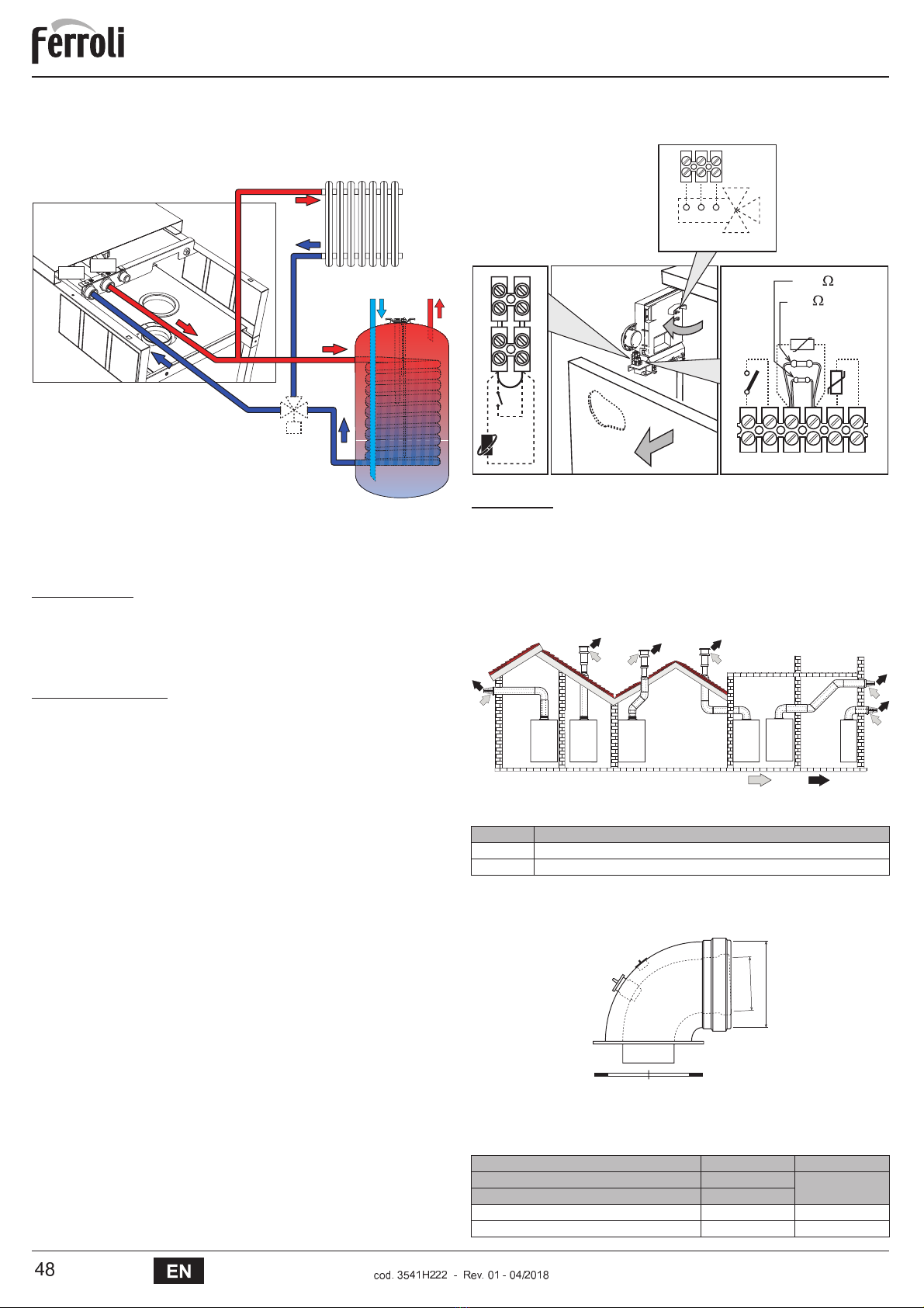
Carry out the relevant connections according to the diagram in fig. 13 and the symbols
on the unit.
fig. 13 - Plumbing connections
Antifreeze system, antifreeze fluids, additives and inhibitors
When necessary, antifreeze fluids, additives and inhibitors can be used only if the man-
ufacturer of such fluids or additives guarantees that they are suitable and do not cause
damage to the exchanger or other components and/or materials of the boiler and system.
Do not use generic antifreeze fluids, additives or inhibitors that are not specific for use in
heating systems and compatible with the materials of the boiler and system.
Water system characteristics
In the presence of water harder than 25° Fr (1°F = 10ppm CaCO3), use suitably treated
water in order to avoid possible scaling in the boiler.
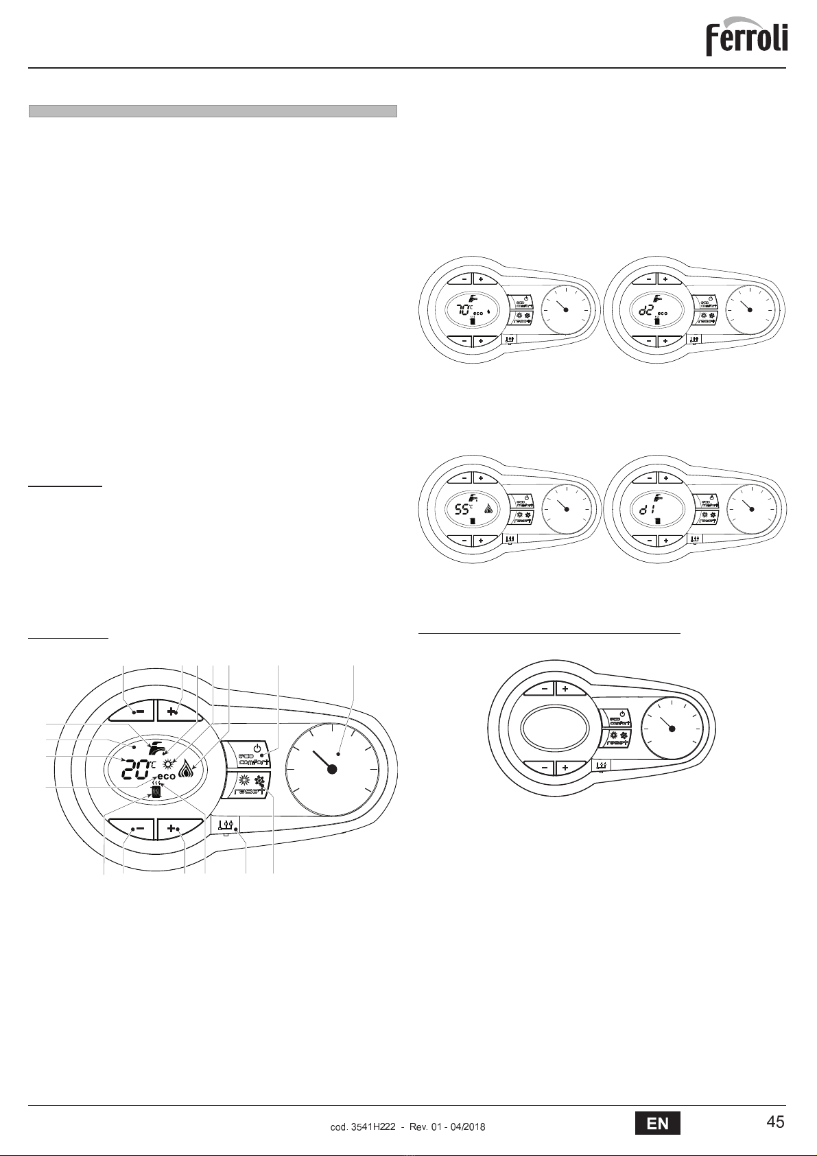
Heating temperature setting
Adjustment can be made from the Remote Timer Control menu
and the boiler control panel.
DHW temperature adjustment
Adjustment can be made from the Remote Timer Control menu
and the boiler control panel.
Summer/Winter Switchover
Summer mode has priority over a possible Remote Timer Control
heating demand.
Eco/Comfort selection
On disabling DHW from the Remote Timer Control menu, the
boiler selects the Economy mode. In this condition, the
eco/com-
fort
button (detail 7 - fig. 1) on the boiler panel is disabled.
On enabling DHW from the Remote Timer Control menu, the
boiler selects the Comfort mode. In this condition it is possible
select one of the two modes with the
eco/comfort
button (detail 7
- fig. 1) on the boiler panel.
Sliding Temperature
Both the Remote Timer Control and the boiler card manage Slid-
ing Temperature adjustment: the boiler card Sliding Temperature
has priority.
20
30
40
50
60
70
80
90
85
20
30
40
50
60
70
80
90
85
1
2
3
4
5
6
8910 7
1
2
3
4
568910 7
OFFSET = 20 OFFSET = 40
1
7
Gas inlet - 1/2”
10
System delivery - 3/4”
11
System return - 3/4”
43 25750 50
11 10 7
%/8(+(/,;%
3.2 Place of installation
% & ' ( ) * + , - . / ) 0 ( / 1 ( , / . / - - ' 2 3 ' 4 5 / . & 1 ' - 6 ' ( . . ) . & ' 6 3 2 ( ' ) 7 / 0 - . 2 3 3 2 . / ) 0
URRPWKHUHIRUHWKHXQLWFDQEHLQVWDOOHGLQDQ\URRP+RZHYHUWKHSODFHRI
LQVWDOODWLRQPXVWEHDGHTXDWHO\YHQWLODWHGWRSUHYHQWWKHFUHDWLRQRIGDQJH
8
URXVFRQGLWLRQVLQFDVHRIHYHQVPDOOJDVOHDNV7KLVVDIHW\UHJXODWLRQLVODLGGRZQ
E\((&'LUHFWLYHQRIRUDOOJDVXQLWVLQFOXGLQJWKRVHZLWKVHDOHGFKDPEHU
9
! ! " ! #

Connection to a storage tank for domestic hot water production
The unit's electronic board is arranged for managing an external storage tank for domes-
tic hot water production. Make the plumbing connections according to the diagram of
fig. 14. Make the electrical connections as shown on the wiring diagram in fig. 32. It is
necessary to use the kit code 1KWMA11W. At the next lighting, the boiler's control sys-
tem recognises the presence of the hot water tank probe and is automatically configures
the DHW function, activating the display and relevant controls.
fig. 14 - Diagram of connection to an external hot water tank
8Domestic hot water outlet
9Cold water inlet
10 System delivery
11 System return
95 Diverter valve
3.4 Gas connection
BBefore making the connection, ensure that the unit is arranged for operation
with the type of fuel available.
The gas must be connected to the relevant connection (see fig. 13) in conformity with the
current standards, using a rigid metal pipe or a continuous surface flexible s/steel tube
and installing a gas cock between the system and boiler. Make sure all the gas connec-
tions are tight.
3.5 Electrical connections
BThe unit must be connected to an efficient earthing system in accordance with
current safety standards. Have the efficiency and suitability of the earthing sys-
tem checked by professionally qualified personnel; the Manufacturer declines
any liability for damage caused by failure to earth the system.
The boiler is prewired and provided with a "Y" type cable (without plug) for con-
nection to the electric line. The connections to the grid must be made with a per-
manent connection and equipped with a bipolar switch whose contacts have a
minimum opening of at least 3 mm, interposing fuses of max. 3A between the
boiler and the line. Make sure to respect the polarities (LINE: brown wire / NEU-
TRAL: blue wire / EARTH: yellow-green wire) in the connections to the electric
line.
BThe unit's power cable must not be replaced by the user. If the cable gets dam-
aged, switch off the unit and have it replaced only by professionally qualified
personnel. In case of replacement, use exclusively “HAR H05 VV-F” 3x0.75
mm2 cable with maximum ext. diameter of 8 mm.
Room thermostat (optional)
BIMPORTANT: THE ROOM THERMOSTAT MUST HAVE VOLTAGE-FREE
CONTACTS. CONNECTING 230V TO THE ROOM THERMOSTAT TERMI-
NALS WILL PERMANENTLY DAMAGE THE PCB.
When connecting a time control or timer, do not take the power supply for such de-
vices from their cutoff contacts. Their power supply must be taken with a direct con-
nection from the mains or with batteries, depending on the type of device.
Accessing the electrical terminal block
The electrical terminal block (fig. 15) can be accessed after removing the front panel (***
'Opening the front panel' on page 51 ***). The layout of the terminals for the various con-
nections is also given in the wiring diagram in fig. 32.
fig. 15 - Accessing the terminal block
3.6 Fume ducts
Important
The unit is a “C type” with sealed chamber and forced draught; the air inlet and fume out-
let must be connected to one of the following extraction/suction systems. Before instal-
lation, check and carefully follow the instructions. Also, comply with the provisions on the
positioning of wall and/or roof terminals and the minimum distances from windows, walls,
ventilation openings, etc.
For the possible outlet configurations and installation distances, refer to
table 7
and
table 8
.
Connection with coaxial pipes
fig. 16 - Examples of connection with coaxial pipes ( = Air / = Fumes)
Table. 2 - Typology
For coaxial connection, fit the unit with one of the following starting accessories. Any horizon-
tal sections of the fume exhaust must be kept sloping slightly towards the boiler, to prevent
possible condensate from flowing back towards the outside and causing dripping.
fig. 17 Starting accessories for coaxial ducts
Table. 3 - Max. length of coaxial pipes
"#
$
"
11 10
Type Description
C1X
Wall horizontal exhaust and inlet
C3X
Roof vertical exhaust and inlet
Coaxial 60/100 Coaxial 80/125
Max. permissible length (horizontal) 7 m 28 m
Max. permissible length (vertical) 8 m
Reduction factor 90° bend 1 m 0.5 m
Reduction factor 45° bend 0.5 m 0.25 m
%2
1&"
155
!138
& 4 # '1 2
10"#
1$8"#
321
95
(
1)
(
1)
(
&)
(
&)
(
&)
(
1)
%"100
%"60
041001&0
%/8(+(/,;%
:
! ! " ! #

Connection with separate pipes
fig. 18 - Examples of connection with separate pipes ( = Air / = Fumes)
Table. 4 - Typology
For the connection of separate ducts, fit the unit with the following starting accessory (Air
= - Fumes = )
Air inlet = / Fume outlet =
fig. 19 - Starting accessory for separate ducts
Before installation, make sure the maximum permissible length has not been exceeded,
by means of a simple calculation:
1. Completely establish the layout of the system of split flues, including accessories
and outlet terminals.
2. Consult the table 6 and identify the losses in meq (equivalent metres) of every com-
ponent, according to the installation position.
3. Check that the sum total of losses is less than or equal to the maximum permissible
length in table 5.
Table. 5 - Maximum length of separate ducts
Table. 6 - Accessories
Type Description
C1X
Wall horizontal exhaust and intake. The inlet/outlet terminals must be concentric or close enough to be
undergo similar wind conditions (within 50 cm)
C3X
Roof vertical exhaust and intake. Inlet/outlet terminals like for C12
C5X
Wall or roof exhaust and intake separate or in any case in areas with different pressures. The exhaust
and intake must not be positioned on opposite walls.
C6X
Intake and exhaust with separately certified pipes (EN 1856/1)
B2X
Intake from installation room and wall or roof exhaust
IMPORTANT - THE ROOM MUST BE PROVIDED WITH APPROPRIATE VENTILATION
Max. permissible length
80 m
eq
(#*
(
&*
+2* (1*
,-* #0 .,
69
%80
%80
110
%60
%80
041065&0
Losses in m
eq
Air
inlet
Fume exhaust
Vertical Horizontal
Ø 80
PIPE
1 m M/F 1KWMA83W 1.0 1.6 2.0
BEND
45° M/F 1KWMA65W 1.2 1.8
90° M/F 1KWMA01W 1,5 2.0
PIPE SECTION
with test point 1KWMA70W 0.3 0.3
TERMINAL
air, wall 1KWMA85A 2.0 -
fumes, wall with antiwind 1KWMA86A - 5.0
FLUE
Split air/fumes 80/80 010027X0 - 12.0
Fume outlet only Ø80 010026X0 +
1KWMA86U
- 4.0
Ø 60
PIPE
1 m M/F 1KWMA89W 6.0
BEND
90° M/F 1KWMA88W 4.5
REDUCTION
80/60 041050X0 5.0
TERMINAL
fumes, wall with antiwind 1KWMA90A 7.0
ATTENTION: CONSIDER THE HIGH PRESSURE LOSSES OF Ø60 ACCESSORIES;
USE THEM ONLY IF NECESSARY AND AT THE LAST FUME EXHAUST SECTION.
%/8(+(/,;%
;
! ! " ! #

Configuration of flues
Air inlet = / Fume outlet =
Table. 7 - Connection with coaxial pipes
Left outlets
Rear outlets
Right outlets
041001)0
150
750
041001)0
198202
202 198
0
1
4
2
3
750
041001)0 1/356'43
60
750
%/8(+(/,;%
< = > ? @ A B C D E F G G G H I J K A L E H L D M G L E N

Table. 8 - Connection with separate pipes
Left outlets
Rear outlets
Right outlets
85 148
750
117 85 198
750
117 19885
56
105
750
%/8(+(/,;%
< O> ? @ A B C D E F G G G H I J K A L E H L D M G L E N

Connection to collective flues
fig. 20 - Examples of connection to flues ( = Air / = Fumes)
Table. 9 - Typology
If the boiler is to be connected BLUEHELIX B 35 to a collective flue or a single flue with
natural draught, the flue or chimney must be expressly designed by professionally qual-
ified technical personnel in conformity with the current regulations and be suitable for
sealed chamber units equipped with fan.
3.7 Condensate drain connection
The boiler has an internal trap for draining condensate. Fit the inspection union Aand
the hose B, pressing it in. Fill the trap with approx. 0.5 l. of water and connect the hose
to the disposal system.
BATTENTION: The unit must never be operated with the trap empty!
fig. 21 - Condensate outlet connection
4. SERVICE AND MAINTENANCE
4.1 Adjustments
Gas conversion
The unit can operate on Natural Gas or LPG and is factory-set for use with one of these
two gases, as clearly shown on the packing and on the data plate. Whenever a different
gas to that for which the unit is arranged has to be used, a conversion kit will be required,
proceeding as follows:
1. Disconnect the boiler power supply and close the gas cock.
2. Remove the front panel and the panel of the sealed chamber (see fig. 22).
3. Undo the screw and rotate the control panel (see fig. 22).
4. Unscrew the ring Cand Eand remove the gas valve (see fig. 23).
5. Replace nozzle Binserted in the gas pipe with that contained in the conversion kit,
interposing seal D (see fig. 23).
6. Reassemble the valve and check the tightness of the connection.
7. Apply the label, contained in the conversion kit, near the data plate.
8. Refit the front panel.
9. Switch the boiler power on and open the gas cock.
10. Modify the parameter for the type of gas:
SXWWKHERLOHULQVWDQGE\PRGH
SUHVVWKH'+:EXWWRQVGHWDLOVDQGILJ IRUVHFRQGVWKHGLVSOD\VKRZV
“b01“ flashing.
SUHVVWKH'+:EXWWRQVGHWDLOVRUILJ WRVHWSDUDPHWHU00 (for operation
with natural gas) or 01 (for operation with LPG).
SUHVVWKHheating + button (detail 4 - fig. 1) until “b06” flashes on the display.
SUHVVWKHDHW buttons (details 1 or 2 - fig. 1) to set parameter 55 (for operation
with natural gas) or 70 (for operation with LPG).
SUHVVWKH'+:EXWWRQVGHWDLOVDQGILJ IRUVHFRQGV
WKHERLOHUZLOOUHWXUQWRVWDQGE\PRGH
11. Using a combustion analyser connected to the boiler fume outlet, check that the
CO2content in the fumes, with the boiler operating at max. and min. output, matches
that given in the technical data table for the corresponding type of gas.
fig. 22
fig. 23
Type Description
C2X
Intake and exhaust in common flue (intake and exhaust in same flue)
C4X
Intake and exhaust in common and separate flues , but undergoing similar wind conditions
C8X
Exhaust in single or common flue and wall intake
B3X
Intake from installation room by means of concentric duct (that encloses the exhaust) and exhaust in
common flue with natural draught
IMPORTANT - THE ROOM MUST BE PROVIDED WITH APPROPRIATE VENTILATION
($) (2)
(4)
+
6
0'5()
(
E
6
(
+
7
%/8(+(/,;%
< P > ? @ A B C D E F G G G H I J K A L E H L D M G L E N

TEST mode activation
Press the heating buttons (details 3 and 4 - fig. 1) together for 5 seconds to activate the
TEST mode. The boiler lights at the maximum heating power set as described in the fol-
lowing section.
The heating and DHW symbols (fig. 24) flash on the display; the heating power will ap-
pear alongside.
fig. 24 - TEST mode (heating power = 100%)
Press the heating buttons (details 3 and 4 - fig. 1) to increase or decrease the power
(Min.=0%, Max.=100%).
By pressing the DHW “-” button (detail 1 - fig. 1), boiler output is immediately adjusted
to min. (0%). By pressing the DHW “+” button (detail 2 - fig. 1), boiler output is immedi-
ately adjusted to max. (100%).
If the TEST mode is activated and enough hot water is drawn to activate the DHW mode,
the boiler remains in TEST mode but the 3-way valve goes to DHW.
To deactivate the TEST mode, press the heating buttons (details 3 and 4 - fig. 1) together
for 5 seconds.
The TEST mode is automatically deactivated in any case after 15 minutes or on stopping
of hot water drawing (if enough hot water has been drawn to activate the DHW mode).
Heating power adjustment
To adjust the heating power, switch the boiler to TEST mode (see sec. 4.1). Press the
heating buttons fig. 1 (details 3 and 4 - ) to increase or decrease the power (min. = 00 -
max. = 100). Press the RESET button within 5 seconds and the max. power will remain
that just set. Exit TEST mode (see sec. 4.1).
4.2 Startup
Before lighting the boiler
&KHFNWKHVHDORIWKHJDVV\VWHP
&KHFNFRUUHFWSUHILOOLQJRIWKHH[SDQVLRQWDQN
)LOOWKHZDWHUV\VWHPDQGPDNHVXUHDOODLUFRQWDLQHGLQWKHERLOHUDQGWKHV\VWHP
has been vented.
0DNHVXUHWKHUHDUHQRZDWHUOHDNVLQWKHV\VWHP'+:FLUFXLWVFRQQHFWLRQVRUERLOHU
&KHFNFRUUHFWFRQQHFWLRQRIWKHHOHFWULFDOV\VWHPDQGHIILFLHQF\RIWKHHDUWKLQJV\VWHP
0DNHVXUHWKHJDVSUHVVXUHIRUKHDWLQJLVWKDWUHTXLUHG
0DNHVXUHWKHUHDUHQRIODPPDEOHOLTXLGVRUPDWHULDOVLQWKHLPPHGLDWHYLFLQLW\RI
the boiler
Checks during operation
6ZLWFKWKHXQLWRQ
&KHFNWKHWLJKWQHVVRIWKHIXHOFLUFXLWDQGZDWHUV\VWHPV
&KHFNWKHHIILFLHQF\RIWKHIOXHDQGDLUIXPHGXFWVZKLOHWKHERLOHULVZRUNLQJ
&KHFNWKHFRUUHFWWLJKWQHVVDQGHIILFLHQF\RIWKHFRQGHQVDWHUHPRYDOV\VWHPDQGWUDS
0DNHVXUHWKHZDWHULVFLUFXODWLQJSURSHUO\EHWZHHQWKHERLOHUDQGV\VWHPV
0DNHVXUHWKHJDVYDOYHPRGXODWHVFRUUHFWO\LQKHDWLQJDQGGRPHVWLFKRWZDWHUSUR
duction.
&KHFNSURSHUOLJKWLQJRIWKHERLOHUE\WXrning it on and off several times with the room
thermostat or remote control.
0DNHVXUHWKHIXHOFRQVXPSWLRQLQGLFDWHGRQWKHPHWHUPDWFKHVWKDWJLYHQLQWKH
technical data table on cap. 5.
0DNHVXUHWKDWZLWKQRKHDWLQJGHPDQGWKHEXUQHUFRUUHFWO\OLJKWVRQRSHQLQJDKRW
ZDWHUWDS&KHFNWKDWWKHKHDWLQJFLUFXODWLQJSXPSVWRSVRQRSHQLQJDKRWZDWHUWDS
during heating operation and there is a regular production of hot water.
&KHFNFRUUHFWSURJUDPPLQJRIWKHSDUDPHWHUVDQGFDUU\RXWDQ\UHTXLUHGFXVWRPL
sation (compensation curve, power, temperatures, etc.).
4.3 Maintenance
Opening the front panel
To open the boiler casing pull the panel outwards and release it (see fig. 25).
BBefore carrying out any operation inside the boiler, disconnect the power
and close the gas cock upstream.
fig. 25 - Front panel opening
Periodical check
7RHQVXUHSURSHURSHUDWLRQRIWKHXQLWRYHUWLPHKDYHTXDOLILHGSHUVRQQHOFDUU\RXWD
\HDUO\LQVSHFWLRQSURYLGLQJIRUWKHIROORZLQJFKHFNV
7KHFRQWURODQGVDIHW\GHYLFHVJDVYDOYHIORZPHWHUWKHUPRVWDWVHWFPXVWIXQF
tion correctly
7KHIXPHH[KDXVWFLUFXLWPXVWEHSHUIHFWO\HIILFLHQW
7KHVHDOHGFKDPEHUPXVWEHWLJKW
7KHDLUIXPHHQGSLHFHDQGGXFWVPXVWEHIUHHRIREVWUXFWLRQVDQGOHDNV
7KHEXUQHUDQGH[FKDQJHUPXVWEHFOHDQDQGIUHHRIGHSRVLWV)RUSRVVLEOHFOHDQLQJ
do not use chemical products or wire brushes
7KHHOHFWURGHPXVWEHSURSHUO\SRVLWLRQHGDQGIUHHRIVFDOH
7KHJDVDQGZDWHUV\VWHPVPXVWEHWLJKW
7KHZDWHUSUHVVXUHLQWKHFROGZDWHUV\VWHPPXVWEHDERXWEDURWKHUZLVHEULQJ
it to that value
7KHFLUFXODWLQJSXPSPXVWQRWEHEORFNHG
7KHH[SDQVLRQWDQNPXVWEHILOOHG
7KHJDVIORZDQGSUHVVXUHPXVWFRUUHVSRQGWRWKDWJLYHQLQWKHUHVSHFWLYHWDEOHV
7KHFRQGHQVDWHHYDFXDWLRQV\VWHPPXVWEHHIILFLHQWZLWKQROHDNDJHRUREVWUXFWLRQV
7KHWUDSPXVWEHIXOORIZDWHU
0
1
4
2
3
%/8(+(/,;%
< Q> ? @ A B C D E F G G G H I J K A L E H L D M G L E N

4.4 Troubleshooting
Diagnostics
In case of operation faults or problems, the display flashes and the fault identification
code appears.
There are faults that cause permanent shutdown (marked with the letter “A”): to restore
operation just press the reset button (detail 6 -fig. 1) for 1 second or RESET on the op-
tional remote timer control if installed; if the boiler fails to start, it is necessary to firstly
eliminate the fault.
Faults marked with the letter “F” cause temporary shutdowns that are automatically reset
as soon as the value returns within the boiler's normal working range.
Table of faults
Table. 10 - List of faults
5. TECHNICAL DATA AND CHARACTERISTICS
Table. 11 - Key of figures cap. 5
5.1 General view and main components
fig. 26 - Front view
Fault
code Fault Possible cause Cure
A01
No burner ignition
No gas
Check the regular gas flow to the
boiler and that the air has been
eliminated from the pipes
Ignition/detection electrode fault
Check the wiring of the electrode and
that it is correctly positioned and free
of any deposits
Faulty gas valve Check the gas valve and replace it if
necessary
Insufficient gas supply pressure Check the gas supply pressure
Trap blocked Check the trap and clean it if
necessary
A02
Flame present signal with
burner off
Electrode fault Check the ionisation electrode wiring
Card fault Check the card
A03
Overtemperature protection
activation
Heating sensor damaged Check the correct positioning and
operation of the heating sensor
No water circulation in the system Check the circulating pump
Air in the system Vent the system
A04
Fume extraction duct safety
device activation
Fault F07 generated 3 times in the
last 24 hours
See fault F07
A05
Fan protection activated Fault F15 generated for 1 hour (con-
secutive) See fault F15
A06
No flame after ignition stage
(6 times in 4 minutes)
Ionisation electrode fault Check the position of the ionisation
electrode and replace it if necessary
Flame unstable Check the burner
Gas valve Offset fault Check the Offset adjustment at mini-
mum power
air/fume ducts obstructed
Remove the obstruction from the flue,
fume extraction ducts and air inlet and
terminals
Trap blocked Check the trap and clean it if
necessary
F07
High fume temperature The fume probe detects an
excessive temperature Check the exchanger
F10
Delivery sensor 1 fault
Sensor damaged
Check the wiring or replace the sensorWiring shorted
Wiring disconnected
F11
Return sensor fault
Sensor damaged
Check the wiring or replace the sensorWiring shorted
Wiring disconnected
F12
DHW sensor fault
Sensor damaged
Check the wiring or replace the sensorWiring shorted
Wiring disconnected
F13
Fume probe fault
Probe damaged Check the wiring or replace the fume
probe
Wiring shorted
Wiring disconnected
F14
Delivery sensor 2 fault
Sensor damaged
Check the wiring or replace the sensorWiring shorted
Wiring disconnected
F15
Fan fault
No 230V power supply Check the 8-pin connector wiring
Tachometric signal interrupted Check the 8-pin connector wiring
Fan damaged Check the fan
F34
Supply voltage under 170V Electric mains trouble Check the electrical system
F35
Faulty mains frequency Electric mains trouble Check the electrical system
F37
Incorrect system water
pressure
Pressure too low Fill the system
Water pressure switch damaged or
not connected Check the sensor
F39
External probe fault
Probe damaged or wiring shorted Check the wiring or replace the sensor
Probe disconnected after activating
the sliding temperature
Reconnect the external probe or
disable the sliding temperature
A42
Heating sensor fault Sensor damaged Replace the sensor
F43
Exchanger protection activa-
tion.
No system H
2
O circulation Check the circulating pump
Air in the system Vent the system
F52
Heating sensor fault Sensor damaged Replace the sensor
A61
Controller
ABM03
fault Controller
ABM03
internal error Check the earth connection and
replace the controller if necessary.
A62
No communication between
controller and gas valve
Controller not connected Connect the controller to the gas valve
Valve damaged Replace the valve
A63
F64
A65
F66
Controller
ABM03
fault Controller
ABM03
internal error Check the earth connection and
replace the controller if necessary.
A23
A24
F20
F21
A26
F40
F47
Card parameter fault Wrong card parameter setting Check the card parameter and modify
it if necessary.
7
Gas inlet
138
External probe (optional)
10
System delivery
139
Remote timer control (optional)
11
System return
145
Pressure gauge
14
System safety valve
154
Condensate drain pipe
16
Fan
155
Hot water tank temperature probe (optional)
32
Heating circulating pump
186
Return sensor
36
Automatic air vent
191
Fume temperature sensor
44
Gas valve
193
Trap
56
Expansion tank
241
Automatic bypass
72
Room thermostat (optional)
74
System filling cock
275
Heating system drain cock
81
Ionisation/ignition electrode
278
Double sensor (Safety + Heating)
95
Diverter valve (optional)
350
Fan/Burner assembly
114
Water pressure switch
A
ON/OFF switch (configurable)
Fault
code Fault Possible cause Cure
R S T U V W X YZ [ \ ] ^ _ ` Z [ \ ] ^ a \ b a X YZ [ \ ] ^ c X d c e \ ^ ] Z Y
%/8(+(/,;%
f g h
f g g
6HQVRUSRVLWLRQLQJ +HDWLQJVHQVRUGHWDFKHGIURP
SLSH
&KHFNWKHFRUUHFWSRVLWLRQLQJDQG
RSHUDWLRQRIWKHKHDWLQJVHQVRU
i j k l m n o p q r s t t t u v w x n y r u y q z t y r {

fig. 27 - Side view
fig. 28 - Rear view
fig. 29 - Top view (AIR INLET = / FUME OUTLET = )
5.2 Water circuit
fig. 30 - Water circuit
11
10
7
43 25750 50
14
241
11107
117 85
14985
210
278 193
14
241
114
56
186
74
32
275
10 11
154 36
| } ~
%/8(+(/,;%
i ik l m n o p q r s t t t u v w x n y r u y q z t y r {

5.3 Diagrams
Circulating pump head / pressure losses
fig. 31 - Circulating pump head / Pressure losses BLUEHELIX B 35
A = Boiler pressure losses - B = Circulating pump min. speed - C = Circulating pump
max. speed
AFor correct modulation, the speed selector on the pump must be set to III.
5.4 Technical data table
The column on the right gives the abbreviation used on the data plate.
Data Unit BLUEHELIX B 35
Max. heating capacity kW 32.0 (Q)
Min. heating capacity kW 6.7 (Q)
Max. Heat Output in heating (80/60°C) kW 31.4 (P)
Min. Heat Output in heating (80/60°C) kW 6.6 (P)
Max. Heat Output in heating (50/30°C) kW 34.0
Min. Heat Output in heating (50/30°C) kW 7.2
Efficiency Pmax (80-60°C) % 98.
Efficiency Pmin (80-60°C) % 97.8
Efficiency Pmax (50-30°C) % 106.1
Efficiency Pmin (50-30°C) % 107.5
Efficiency 30% % 10.8
Efficiency class Directive 92/42 EEC -
NOx emission class - 5 (NOx)
Gas supply pressure G20 mbar 20
Max. gas delivery G20 m
3
/h 3.3
Min. gas delivery G20 m
3
/h 0.71
CO
2
max. G20 % 9.0
CO
2
min. G20 % 8.70
Gas supply pressure G31 mbar 37
Max. gas delivery G31 kg/h 2.
Min. gas delivery G31 kg/h 0.52
CO
2
max. G31 % 10.70
CO
2
min. G31 % 9.80
Max. working pressure in heating bar 3 (PMS)
Min. working pressure in heating bar 0.8
Max. heating temperature °C 90 (tmax)
Heating water content litres
Heating expansion tank capacity litres 10
Heating expansion tank prefilling pressure bar 0.8
Protection rating IP X5D
Power supply voltage V/Hz 230V/50Hz
Electrical power input W 1
Empty weight kg 50
Type of unit C13-C23-C33-C43-C53-C63-C83-B23-B33
PIN CE 0461CM0988
Q !"#$
H %&H'($
(
+
6
0 0$5 1 1$5 2 2$5 3
6
5
4
3
2
1
0
%/8(+(/,;%
i k l m n o p q r s t t t u v w x n y r u y q z t y r {

¡
¢ £
¤ ¥
¢ £ ¦ ¥
§ ¦ ¥
¨ ¨ ¦ ¢
¤ ¨ ¦ ¤
© ¦ © § ¨
© ¦ © £ ª
© ¦ © © ¢
© ¦ © ¥ ¢
© ¦ © © ©
«¤
«§
¢ ©
¬ ® ¯
° ± ® ² ³ ´ µ ® ¶ · ³ ¸ ³
° ± ® ² ³ ´ ® ² ² ¹ º ¹ ® » º ¼
½ ³ ¾ ¹ ´ ¹ ¶ ¿ ¼ ® ´ ® º ¿ ¹ º ¹ ¼ º · » ± ³ ¯ ¸ ¹ · »
À µ ® ¿ ¹ ® ¯ ±
Á Â Ã Ä Å Æ Ã Ç Ä È Ã É Â Ê Â Ã Ë Ì Æ Í Â Æ Â Î Í Ï Â Ð Ð Ì É Ì Â Æ É Ï É Ç Ã Ä Ä
ÑÃ Ë Â Ò Ê Â Ã Ë Å Ó Ë È Ó Ë
Á Â Ã Ä Å Æ Ã Ç Ä È Ã É Â Ê Â Ã Ë Ì Æ Í Â Æ Â Î Í Ï Â Ð Ð Ì É Ì Â Æ É Ï
Ô Ä Â Ð Ó Ç Ê Â Ã Ë Å Ó Ë È Ó Ë Ã Ë Î Ã Ë Â Ò Ê Â Ã Ë Å Ó Ë È Ó Ë Ã Æ Ò Ê Ì Í Ê Õ Ë Â Ö È Â Î Ã Ë Ó Î Â Î Â Í Ì Ö Â × Ø Ù
Ô Ä Â Ð Ó Ç Ê Â Ã Ë Å Ó Ë È Ó Ë Ã Ë ¢ © Ú Å Ð Î Ã Ë Â Ò Ê Â Ã Ë Å Ó Ë È Ó Ë Ã Æ Ò Ç Å Û Õ Ë Â Ö È Â Î Ã Ë Ó Î Â Î Â Í Ì Ö Â × Ø Ø Ù
Ô Ä Â Ð Ó Ç Â Ð Ð Ì É Ì Â Æ É Ï Ã Ë Î Ã Ë Â Ò Ê Â Ã Ë Å Ó Ë È Ó Ë Ã Æ Ò Ê Ì Í Ê Õ Ë Â Ö È Â Î Ã Ë Ó Î Â Î Â Í Ì Ö Â × Ø Ù
Ô Ä Â Ð Ó Ç Â Ð Ð Ì É Ì Â Æ É Ï Ã Ë ¢ © Ú Å Ð Î Ã Ë Â Ò Ê Â Ã Ë Å Ó Ë È Ó Ë Ã Æ Ò Ç Å Û Õ Ë Â Ö È Â Î Ã Ë Ó Î Â Î Â Í Ì Ö Â × Ø Ø Ù
¡ Ë Ð Ó Ç Ç Ç Å Ã Ò
¡ Ë È Ã Î Ë Ç Å Ã Ò
Ü Æ Ä Ë Ã Æ Ò Ý Ï Ö Å Ò Â
Á Ë Ã Æ Ò Ý Ï Ê Â Ã Ë Ç Å Ä Ä
Ü Í Æ Ì Ë Ì Å Æ Ý Ó Î Æ Â Î È Å Û Â Î É Å Æ Ä Ó Ö È Ë Ì Å Æ
¡ Æ Æ Ó Ã Ç Â Æ Â Î Í Ï É Å Æ Ä Ó Ö È Ë Ì Å Æ
Á Å Ó Æ Ò È Å Û Â Î Ç Â Þ Â Ç
ßÖ Ì Ä Ä Ì Å Æ Ä Å Ð Æ Ì Ë Î Å Í Â Æ Å à Ì Ò Â Ä
á¿ ¶ â ® ¯ ¶ ¿ ã ä å æ ç ç À è ¬
é Å Æ Ò Â Æ Ä Ì Æ Í Ý Å Ì Ç Â Î ê ë ßÁ
ì Å Û Õ Ë Â Ö È Â Î Ã Ë Ó Î Â Ý Å Ì Ç Â Î × Ø Ø Ù ê í î
ï£ïÅ Ì Ç Â Î ê í î
é Å Ö Ý Ì Æ Ã Ë Ì Å Æ Ê Â Ã Ë Â Î ê í î
é Å Í Â Æ Â Î Ã Ë Ì Å Æ Ä È Ã É Â Ê Â Ã Ë Â Î ê í î
ð ñ ò ó ô õ ö ÷ ø ù ú û ù ü ý ø þ ü ù ü ù õ ô ú ù ú ù ý ÿ
ü ù ø þ ü ÿ ø ù ú û ù ü ý ø þ ü ù ý ø ö ù ý ø ù ü ô ÿ
ù ø ý ÿ
ù ù
ø ù ú û ù ü ý ø þ ü ù ý ø ö ù ý ø ù ü
þ ø
ù ø
ð ñ ñ ò
ø ù ú û ù ü ý ø þ ü ù ú ù ý ÿ
ü
ÿ
ù ÿ
ô ÿ õ
ô
ù ü
ü
÷ ø ù ú û ù ü ý ø þ ü ù
ô
ù ü
ý ÿ
ü
ø ö ù ü ö ù ý ø ù ü
ü ù ø þ ü ÿ ø ù ú û ù ü ý ø þ ü ù ð ý ø ö ù ý ø ù ü ô ÿ
ù ø ò
¼ ¯
· ´ ° » ¹
¶ ´ ³ ®
»
® ´ ¯ ¶ ¾
® ´ ¯ ¹ »
±
¼
¹
»
æ
è
½
À ¾
ã
ã
ã
ã
ã
ã
ã
ã
!
â
¯
"
ã
µ
ȘV
Ș
Ș
%/8(+(/,;%
# $
% & ' ( ) * + , - . . . / 0 1 2 ( 3 , / 3 + 4 . 3 , 5

5.5 Wiring diagram
fig. 32 - Wiring diagram
AAttention: Remove the jumper on the terminal block before connecting the room thermostat or remote timer control.
7 7
1
/
9DF
+]
6 7 8 9 : ; < ; ; ; = ; = > ? 6 7
8 9 : ; < ; ; ; =; > ; ? ; 6 ; 7 ; 8 ; 9 ; : = < = ; = = = > = ?
;
9
@
A
B
C
D E
E
F G H I J
K L M
; = > ?
; = > ? 6 7 8 9 :
; < ; ; ; = ; > ; ? ; 6 ; 7 ; 8 ; 9
> ? 6 7; =
3:1
*1'
)86($
9
'
N O
P Q P R P S P O
; 9
; =
;
=
;
;
;
P T
= ?
9
;
=
$
N
N
%/8(+(/,;%
N
# U
% & ' ( ) * + , - . . . / 0 1 2 ( 3 , / 3 + 4 . 3 , 5
Table of contents
Popular Industrial Equipment manuals by other brands

Endress+Hauser
Endress+Hauser Stamoclean CAT430 operating instructions

LNS
LNS QUICK SIX troubleshooting manual

Orion
Orion L77-VP instruction manual

New Focus
New Focus 9091 user guide

Siemens
Siemens SIVACON 8PS BD2 Series installation instructions

Electrostatic Technology
Electrostatic Technology 802 manual