Contents:
4.10. Hydraulic Unit
4.10.1. Setting of the Vice Clamping Force
4.11. Cooling System
5. Commissioning
5.1. Security Check
5.2. Cutting Procedure
6. Machine Maintenance
6.1. Cleaning
6.2. Removal/disposal of chips
6.3. Coolant system cleaning
6.4. Lubrication
6.4.1. Lubrication points in ARG 260 CF-NC
6.4.2. Lubrication points in ARG 300 CF-NC, ARG 330 CF-NC
ARG 300 DCT CF-NC, ARG 330 DC CF-NC
6.4.3. Lubrication points ARG 520 DC CF-NC
6.5. Principles of Hydraulic Unit Maintenance
6.5.1. Work safety
6.5.2. Commissioning
6.5.3. Hydraulic Liquids
6.5.4. Hydraulic Mineral Oils
6.5.5. Service intervals
6.5.6. Oil Refill and Filter Replacement
7. Faults and Remedies
7.1. Repairs
7.2. Failures - Potential Causes and Remedies
8. Saw Blades
8.1. Saw Blade Design
8.2. Selection of Tooth Size
8.3. Optimum Workpiece Clamping
8.4. Running-in New Saw Blades
8.5. Factors Influencing Saw Blade Service Life
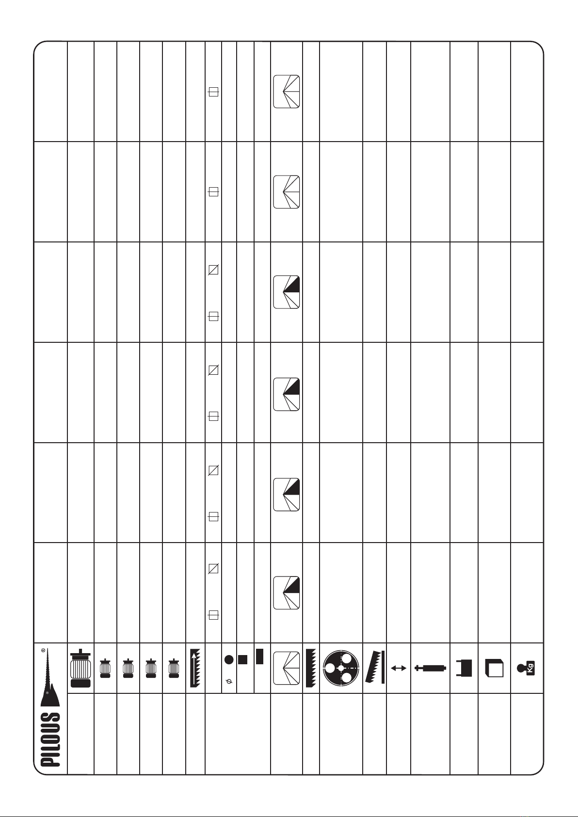
8.6. Values Recommended for Cutting
9. Nameplate
10. Electrical Wiring Diagram
11. Hydraulic Unit Wiring Diagram
11.1. Hydraulic Unit Wiring Diagram
ARG 260 CF-NC, ARG 300 CF-NC, ARG 330 CF-NC
ARG 300 DCT CF-NC, ARG 330 DC CF-NC
11.2. Hydraulic Unit Wiring Diagram for ARG 520 DC CF-NC
12. Accessories
12.1. Laser Guideline Light
12.1.1. Activation and Deactivation of the Laser Beam
12.1.2. Laser Indication on the Machine
12.1.3. Adjustment
12.2. Oil Mist Lubrication
12.3. Vertical Vice for HVP Bundle Cutting
0. General
0.1. Safety Provisions
0.2. Scope of Use / Use According to Designation
0.3. Requirements on Operators
0.4. Machine Requirements - Safety Devices
0.5. Protective Covers
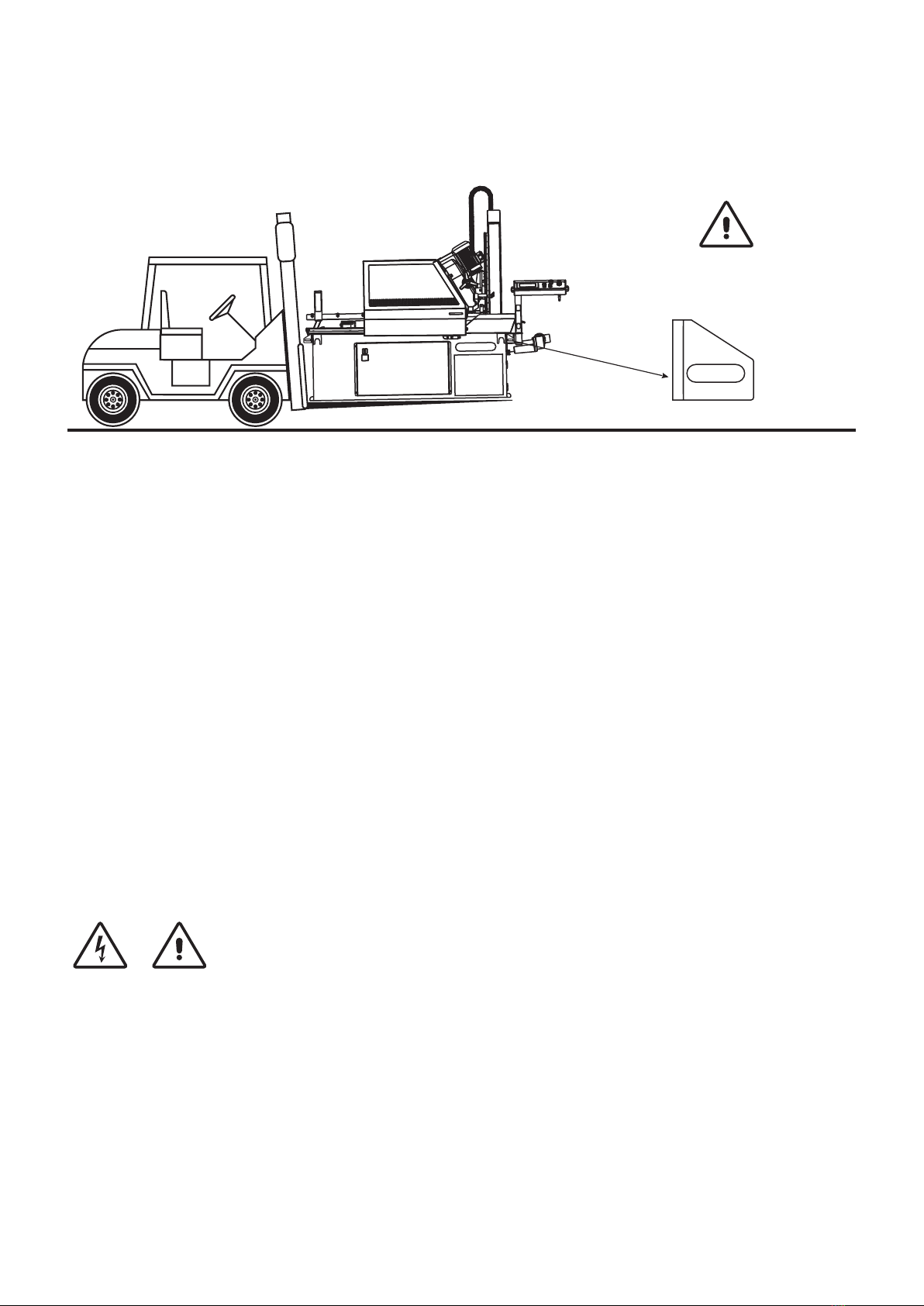
1. Transport and Storage
1.1. Surface Protection
1.2. Packing
1.3. Disassembly/Repacking
1.4. Disposal
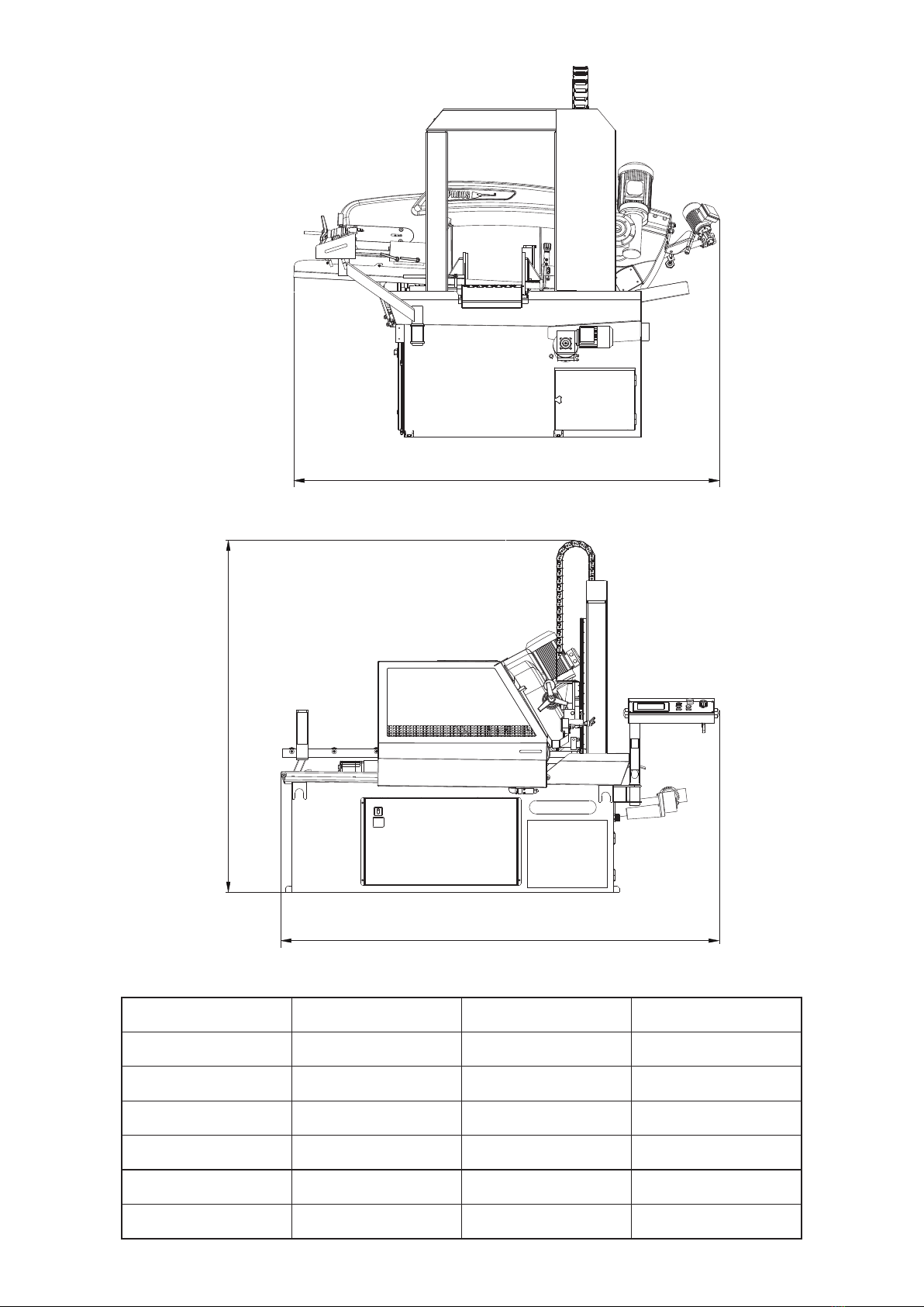
2. Technical Data
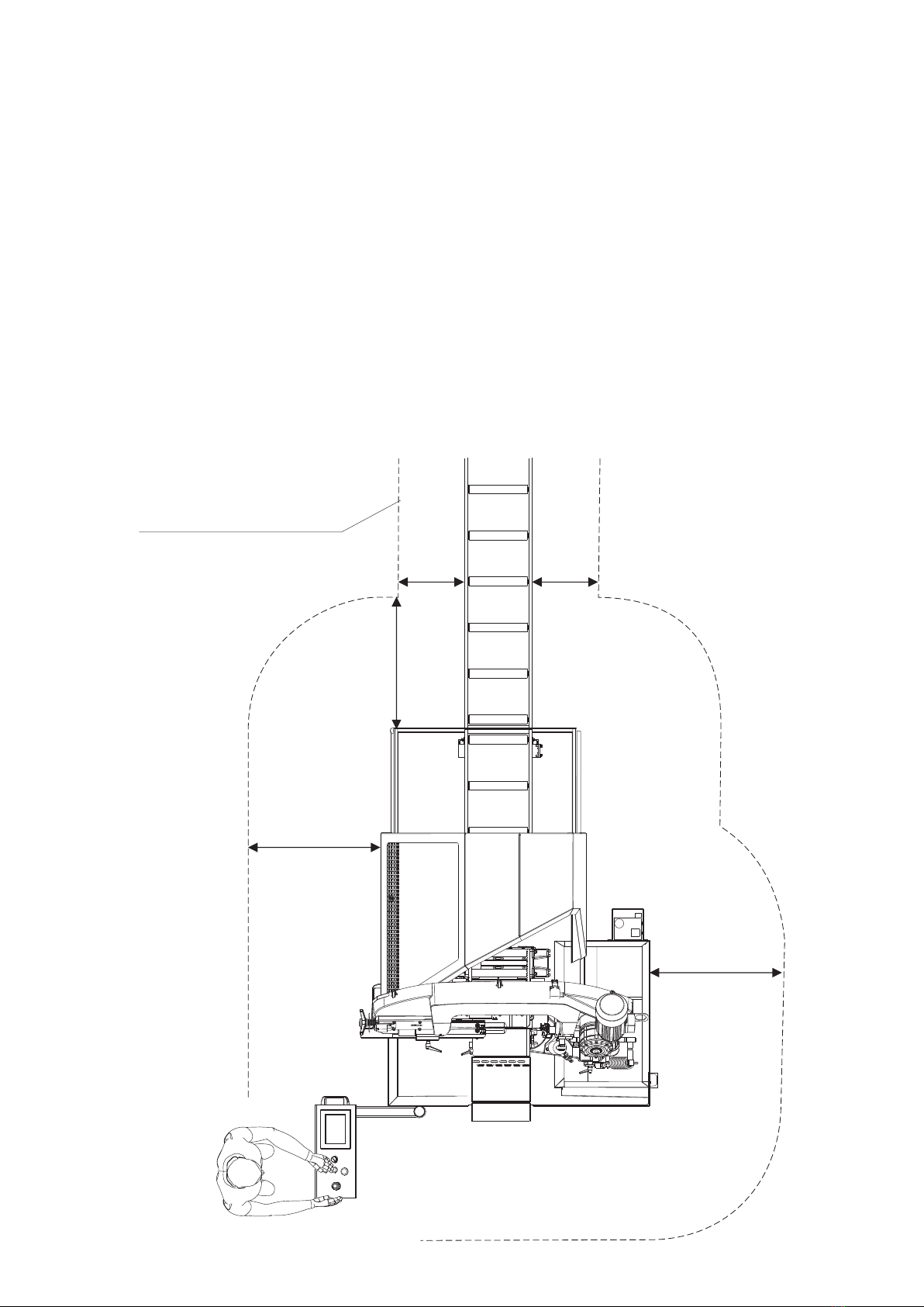
3. Installation
3.1. Space Requirements
3.2. Removal of Temporary Transport Beams
and Fixation of the Machine
3.3. Machine Installation
3.4. Connection to the Mains
3.5. Releasing the ARG 520 DC CF-NC
4. Machine Description
4.1. Control Panel
4.1.1. Home screen / Main menu
4.1.2. Automatic mode
4.1.3. Semi-automatic mode
4.1.4. Manual mode
4.1.5. Series
4.1.6. Side menu
4.2. Control Valve - Saw Blade Feed to the Cut
4.3. Saw Blade Feed Pressure Control
4.4. Vice
4.4.1. Cutting Angle Settings
4.4.2. Adjustment Procedure – Lateral Play of the Vice
4.4.3. Feed system of the movable vice
4.4.4. Setting of the auxiliary roller
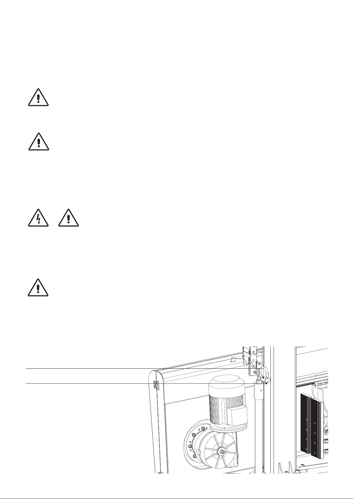
4.5. Removal of Protective Housing
4.5.1. Protective cover removal in
ARG 260 CF-NC, ARG 300 CF-NC,
ARG 300 DCT CF-NC, ARG 330 CF-NC,
ARG 330 DC CF-NC
4.5.2. Removal of protective covers of the saw blade in
ARG 520 DC CF-NC
4.6. Setting the arm descent endpoint
4.7. Arm - Saw Blade Guidance
4.8. Replacement, Tensioning and Adjustment of the Saw Blade
4.9. Guide Heads Adjustment
4.9.1. Guide Heads - Adjustment in ARG 260 CF-NC,
ARG 300 CF-NC, ARG 300 DCT CF-NC
4.9.2. Guide Heads - Adjustment in ARG 330 CF-NC,
ARG 330 DC CF-NC, ARG 520 DC CF-NC
Dear customer,
thank you for purchasing our product. We wish you a lot of success with it in your business. Please pay close attention to
the following instructions in order to ensure faultless operation of the machine.
© 2018 All rights, particularly the right to make copies of, to distribute and translate this instruction manual, are
reserved. No part of this instruction manual may in any form (printing, copying, microfilm or other means) be reproduced
or stored, processed, copied or distributed using electronic systems without a permission by PILOUS.
ver. 1/12/2018
ORIGINAL INSTRUCTION MANUAL