Ferrovac CTH40 User manual


Operation Manual
CTH40/CTDH40/VSCT40
Page|2/28
Rev. C
Important!
It is the sole responsibility of all users to carefully read the operating instructions and keep
them safe. Read and follow all safety instructions carefully before using the product described
in this document. Ferrovac declines any and all responsibility and liability for any
damage/injuries resulting from incorrect use/adjusting/controlling or programming of the
product.
Warranty
Ferrovac warrants this product to be free of defects in material and workmanship for 24 months from
the date of shipment. In the case of any defects, Ferrovac will either repair or replace the product at our
discretion.
Warranty limitations
The warranty for this product does not apply to defects resulting from the following:
• Non-observance of operational- and safety instructions
• Natural wear of components
• Consumables
• Modifications to our products without our written consent
• Misuse of any product or part of the product
This warranty stands in place of all other warranties, implied or expressed, including any implied
warranty of implied merchantability or fitness for a particular use. The remedies provided herein are the
buyer’s sole and exclusive remedies.
Neither the company Ferrovac nor any of its employees shall be liable for any direct, indirect, incidental,
consequential or special damages arising out of the use of its products even if Ferrovac has been advised
of the possibility of such damages. Such excluded damages shall include but are not limited to: costs of
removal and installation, losses sustained as the result of injury to any person, or damage to property.
Copyright
Copyright 2022 Ferrovac. All rights reserved. All information in this document is the sole property of
Ferrovac and is protected by Swiss copyright laws and international conventions. Ferrovac grants the
right for reproduction for the purchasers own use. No part of this manual may be reproduced or
transmitted by any third party in any form or by any means and for any purpose without the written
permission of Ferrovac.

Operation Manual
CTH40/CTDH40/VSCT40
Page|3/28
Rev. C
Contents
Terms and Symbols.............................................................................................................5
General Information............................................................................................................................ 6
Technical Specifications............................................................................................................ 9
1 Introduction..................................................................................................................... 11
2 Unpacking and inspection..........................................................................................11
3 Overview and description..........................................................................................13
4 Setup and installation................................................................................................13
4.1 Installation on a UHV chamber ...............................................................................................13
4.2 Temperature measurement and heating ...............................................................................15
4.3 Installation for cool-down.......................................................................................................16
5 Preparation for vacuum usage, venting......................................................................17
5.1 Pump-down ............................................................................................................................17
5.2 Venting....................................................................................................................................17
6 Cool down procedures 17
6.1 Cool-down of the dewar version CTDH40 .............................................................................. 17
6.2 Cool-down of the tube version CTH40 . .................................................................................. 17
6.2.1 Cool-down with a pressurized liquid nitrogen dewar ..........................................................17
6.2.2 Cool-down with liquefying N₂gas . .....................................................................................17
7 Warm up procedures..................................................................................................19
7.1 Warm up CTH40..................................................................................................................... 19
7.1.1 Warm-up by heating with the heating coil ........................................................................19
7.1.2 Warm-up with hot gas........................................................................................................20
7.2 Warm-up CTDH40 .................................................................................................................21
8 Maintenance..............................................................................................................21
8.1 Bake-out . .............................................................................................................................. 21
8.2 Cleaning.................................................................................................................................22
9 Performance data...........................................................................................................22
9.1 Cool-down and warm up of VSCT40 .....................................................................................22
9.2 Cool-down and warm up of VSCT40 with the new CTH40 installed......................................23
10 Wiring, cable layouts, temperature conversion ....................................................................23

Operation Manual
CTH40/CTDH40/VSCT40
Page|4/28
Rev. C
10.1 Temperature sensor ............................................ ...............................................................23
11 Upgrades and options...............................................................................................................29
11.1 Configured cabling.............................................................................................................. 29
11.2 Kit with cabling and power supply.......................................................................................29
12 Additional information..............................................................................................................29
12.1 Return of defective items ....................................................................................................29
12.2 Download ............................................................................................................................29
List of Figures
1 Symbols used in the drawings................................................................................................... 5
2 Overview drawings of the CTH40 (top) and CTDH40 (bottom) with their components.
The original drawings can be downloaded from our homepage in the
category UHV suitcase accessories.......................................................................................... 10
3 Example image for usage of the VSCT40 with cold trap and our NexGeneration
UHV suitcase........................................................................................................................... 11
4 Overview of the CTH40 (left) and CTDH40 (right) with their components........................... 12
5 Demonstration of mounting orientations for the CTDH40 and CTH40. The CTDH40
should only mounted in the up-right orientation.................................................................... 14
6 Schematic example for the usage of the VSCT40 with a chamber together with
our NexGeneration UHV suitcase. (Be aware that the valve and short flanges of
the VSCT40 have tapped holes.) ............................................................................................ 14
7 Flow chart for cooling with N2 gas and heat exchanger......................................................... 18
8 Examples for a pressure (left) and temperature (right) curves during cool-down
and warm-up of the CT40 (predecessor of CTH40)................................................................ 22
9 Measurement data taken with a VSCT40 on a typical CF63 turbo pump. On the
chamber of the VSCT40 our new VSCTH40 was installed...................................................... 24
10 Pin layout for miniature 6-Pin feed-through for temperature measurement including
Pt-Sensor and filament .......................................................................................................... 25
11 Connection cable layout (CABCTH40HTB4M or CABCTH40HT4M) for temperature
measurement including Pt-Sensor and filament. For the temperature
sensor 4 wires are available, the heating coil only as 2 wires. For the pin layout
of the 6-pin miniature connector please refer to Fig. 10, the pins are connected
respectively............................................................................................................................ 26
12 Graphical conversion of resistance into temperature for the Pt100 sensor.......................... 27
13 The CT-devices are available with a cable and power supply kit............................................ 27
List of Tables
1 Suggestion for a warm-up program for CTH40. (Voltage statements are only
rough numbers as they vary with temperature and exact length of the coil.)....................... 20
2 Suggestion for a warm-up program for CTDH40. (Voltage statements are only
rough numbers as they vary with temperature and exact length of the coil.) ..................... 21

Operation Manual
CTH40/CTDH40/VSCT40
Page|5/28
Rev. C
Terms and Symbols
The information in this document represents the state of the product at the date of print. Technical
changes may be made without notice. Ferrovac AG makes no warranties or representations with respect
to accuracy or completeness of the contents of this publication. Figures and photos are not binding. The
product names used are for identification purposes and may be trademarks of their respective
companies.
Symbol
Meaning
A triangle with explanation mark indicates a passage in the
manual with information that is crucial for the operator. READ
THESE PARAGRAPHS CARE-FULLY or the product might be
damaged by misuse.
A triangle with a snow flake indicates a passage in the manual
with information that is crucial for the operator with respect
to cryo cooling and handling cryogenic liquids. READ THESE
PARAGRAPHS CAREFULLY in order to protect
the operator from any injury.
A triangle with a gas bottle indicates a passage in the manual
with information that is crucial for the operator with respect
to laboratory gases under pressure. READ THESE PARAGRAPHS
CAREFULLY in order to protect the operator from any injury.
WARNING! The WARNING heading in a manual explains dangers that may result in personal injury
or death. Always read the associated information very carefully.
CAUTION! The CAUTION heading in a manual explains hazardous situations that could damage the
product. Such damage may invalidate warranty.
Figure 1 : Symbols used in the drawings.

Operation Manual
CTH40/CTDH40/VSCT40
Page|6/28
Rev. C
General Information
This manual covers all important information about installation, commissioning and operation of your
CTH40/CTDH40/VSCT40. It also provides essential safety information, maintenance- and fault finding
procedures.
The product described was manufactured in accordance with the applicable national standards and
guidelines. The information in this document represents the state of the product at the date of print.
Technical changes may be made without notice. Ferrovac makes no warranties or representations with
respect to accuracy or completeness of the contents of this publication. Figures and photos are not
binding. The product names used are for identification purposes and may be trademarks of their
respective companies.
Designated Use
The product described in this document may only be used for its designated application. Designated use
of the product is defined by the following rules:
The product is:
·Used with original cable sets supplied by Ferrovac which are explicitly specified for the use with
the product described in this publication.
·Used in an indoor research laboratory environment or an industrial production or processing
facility.
·Operated by personnel qualified for operation of delicate scientific equipment.
·Used in accordance with all related manuals.
Important!
Carefully read all safety instructions and relevant manuals before using the product and any
related equipment!
Non Designated Use
Non-designated use is defined if any of the following are true:
·The product is used with other equipment not explicitly acknowledged by Ferrovac in writing.
·The product is used outdoors or at ambient conditions exceeding the values given in the product
specification.
·The product is used by non-qualified persons.
·Operation of the product in disregard of the safety instructions.
·Operation of the product with disabled, modified, removed or damaged safety equipment and
devices.

Operation Manual
CTH40/CTDH40/VSCT40
Page|7/28
Rev. C
General safety Information
Read the safety instructions very carefully. All safety precautions must be strictly observed at all times
while using the product described in this manual and any associated instrumentation.
Study this document to learn how to operate your product correctly. Keep this instruction manual in a
safe place close to the described product and inform all other users of the manual’s location. Always
include this manual when handing the product over to third party persons.
Responsible body is the individual or group of persons that are responsible for the proper use and
maintenance of the product, ensuring that the product is operated within its specifications and
operating limits. The responsible body must ensure that users of the product are adequately trained.
Operators use the product for its intended purpose. Users must be trained in electrical safety, handling
of cryogenic liquids and adequate use of the instrument. They must be protected from electric shock
and other potentially dangerous situations.
Maintenance Personnel perform routine tasks on the product to keep it in proper operating conditions,
i.e. setting up the line voltage or replacing consumables. Maintenance procedures described in this
manual must be followed.
Service Personnel are trained to work on live circuits and to work cryogenic liquids as well as perform
fault finding measurements and repair work to the product. Only fully trained service personnel
qualified to handle potentially lethal voltages may perform servicing and repair.
Shock hazard: The American National Standards Institute states that a shock hazard exists when voltage
levels are greater than 30 V RMS, 42.2 V peak or 60 VDC. A good safety practice is to assume that
hazardous voltages are present in any unknown circuitry.
Operation Manual
CTH40/CTDH40/VSCT40
Page|8/28
Rev. C
Warning!
Always check for correct mains voltage before connecting any equipment!
Mains supply voltage fluctuation must not exceed ±10% of the nominal voltage.
Warning!
• Always observe and strictly follow the safety notes and regulations given in this document
• Always use the originally delivered cables with the product for all electrical connections.
• Always switch off the device before disconnecting cables.
• Never operate the device outside its dedicated environment.
• DO NOT OPEN the device unless you fulfill the requirements of a fully trained service
personnel and you are familiar with live circuits and potentially lethal voltages.
Important! Ambient conditions and environment:
This product is only to be used indoors, in locations meeting the following requirements:
• Room temperature lies between 5 C/41 F and 40 C/104 F
• Humidity up to maximum of 80%
• Altitudes up to 2000m
• Pollution Degree 2 environments

Operation Manual
CTH40/CTDH40/VSCT40
Page|9/28
Rev. C
Technical Specifications
CTH40
·Flange type: DN40CF
·Heat exchanger: Aluminum cooling blocks
·Core : OFHC (Copper), stainless steel
·Heating wire: Kanthal ∅0.3 mm
·Max. hEATING current 4.0 A
·Cryogenic liquids Liquid nitrogen only
·Maximum allowed inlet pressure 2.5 bar
·Temperature sensor type Pt100
·Temperature range sensor -200 C – 170 C
·Maximum heating/baking temperature +150 C
Miniature feedthrough
·Pins 6 × ∅1.6 mm
·Test voltage 500 V DC
·Max. voltage for device usage 49 V
·Max. current 5 A
CTDH40
·Flange type: DN40CF
·Heat exchanger: Aluminum cooling blocks
·Core : OFHC (Copper), stainless steel
·Heating wire: Kantal ∅0.3 mm
·Max. heating current 4.0 A
·Cryogenic liquids Liquid nitrogen only
·Maximum allowed inlet pressure 2.5 bar
·Temperature sensor type Pt100
·Temperature range sensor -200 C – 170 C
·Maximum heating/baking temperature +150 C
Miniature feedthrough
·Pins 6 × ∅1.6 mm
·Test voltage 500 V DC
·Max. voltage for device usage 49 V
·Max. current 5 A
·Flange type DN16CF
VSCT40
·Maximum bakeout temperature 150 C
·Leak rate < 5 × 10¯¹⁰ mbar
·Maximum overpressure 0.3 bar (windows)
·Tolerances for chamber:
·Machine parts ISO 2768 -m -K
·Welded parts ±1 mm and±1°
Operation Manual
CTH40/CTDH40/VSCT40
Page|10 /28
Rev. C
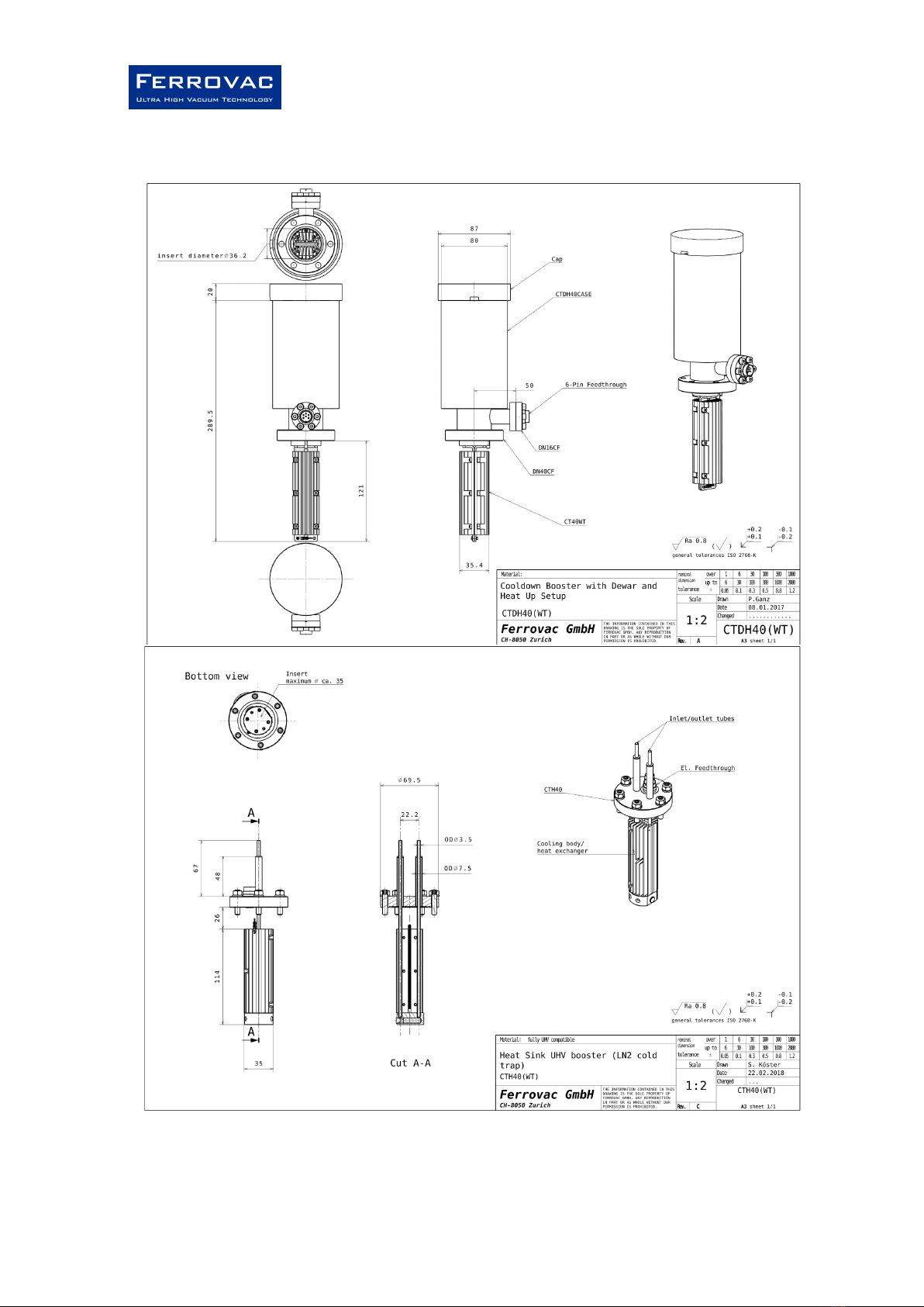
Figure 2: Overview / technical drawing of CTDH40/CTH40 with their components.
All measures are in mm. The original drawings can be downloaded from our homepage
in the category UHV suitcase accessories.
Operation Manual
CTH40/CTDH40/VSCT40
Page|11 /28
Rev. C
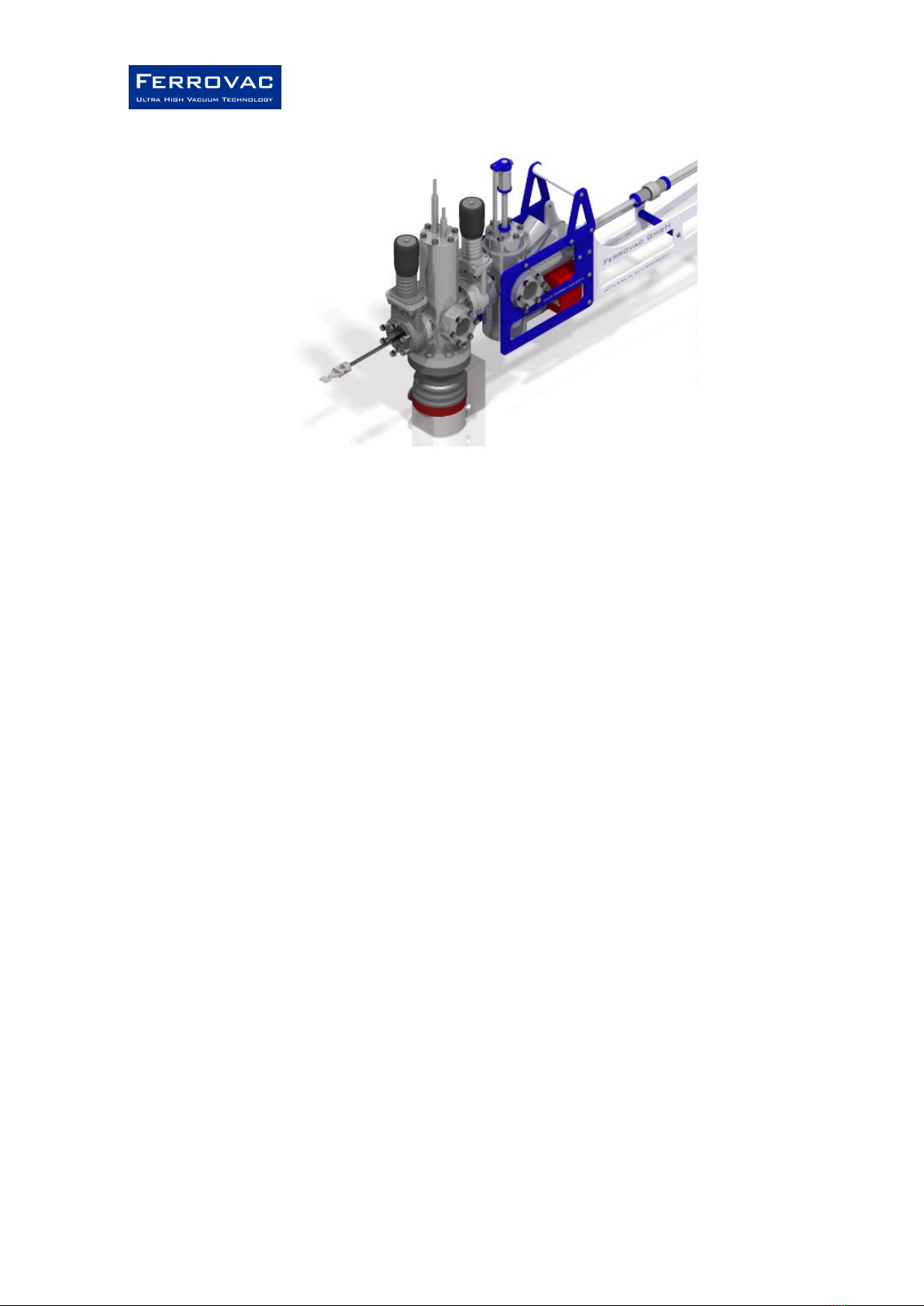
Figure 3: Example for usage of the VSCT40 with cold trap and our NexGeneration UHV suitcase.
1 Introduction
The CTH40 and CTDH40 are UHV boosters intended to be used with a small transfer chamber (for
example as our fast pump down dock VSCT40, Fig. 3). They enable an exceptionally fast transfer of
samples from a portable UHV-suitcase (e.g. VSN40S) into the UHV-System. Vacuum in the transfer
chamber is created using a turbo pumping system while the UHV boosters act as additional cryogenic
pump. Thus a sufficient vacuum is established within approximately 30 minutes, as opposed to many
hours when pumping the buffer volume conventionally. On top the water partial pressure will be
reduced. For a fast warm-up, the CTH40 and CTDH40 can be heated vie a tungsten filament while the
temperature can be monitored via a Pt100 temperature sensor. The CTH40 and CTDH40 can be ordered
as stand-alone products or together with a chamber and valve, the VSCT40. The turbo pumping system
and cool-down equipment are not part of the product. Configured cables can be ordered separately or
as a kit with a small power supply.
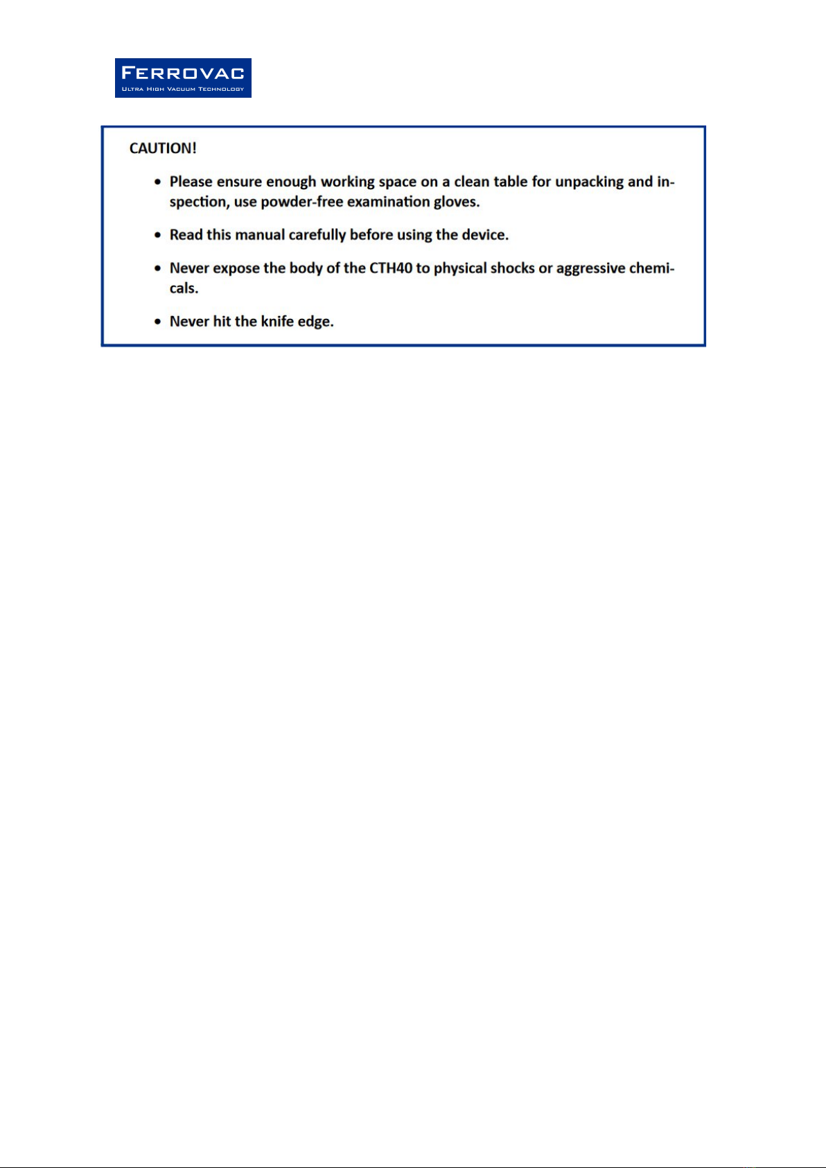
2 Unpacking and inspection
Before unpacking, inspect the parcel for any visible damage. If any evidence for damage of the package
is found, take pictures of the parcel and send them to Ferrovac AG immediately. Compare the contents
of the package with the delivery note. Any damage or missing items must be reported to Ferrovac within
48 hours after delivery. Prepare a very clean workspace. Carefully unpack the CTH40 and perform a
visual check for any damage of the package, its contents and accessories. Only touch the vacuum side
parts of the CTH40 with clean, powder-free gloves. The CTH40 and CTDH40 are shipped fully assembled
as one piece and cleaned, see Fig. 4. Compare the contents of the package with the delivery note any
damage or missing items must be reported to Ferrovac AG within 48 hours after delivery.

Operation Manual
CTH40/CTDH40/VSCT40
Page|12 /28
Rev. C
Figure 4: Overview of the CTH40 (left) and CTDH40 (right) with their components.
The package should contain for CTH40:
• The fully assembled CTH40
• This manual
• Optional: Cabling
• Optional: Subsequent manuals (if applicable e.g. for a kit)
The package should contain for CTDH40:
• The fully assembled CTDH40
• A blue foam cap
• This manual
• Optional: Cabling
• Optional: Subsequent manuals (if applicable e.g. for a kit)
For VSCT40:
• Fully assembled VSCT40 with gate valve (Optional without gate valve)
• This manual
• Optional: cabling
• Subsequent manuals (e.g. gate valve)
Operation Manual
CTH40/CTDH40/VSCT40
Page|13 /28
Rev. C
3 Overview and description
The CTH40 and CTDH40 are cooled down with liquid nitrogen (LΝ₂) in order to cool the cryo pump body
attached on the vacuum side. In case of the CTH40 liquid nitrogen flows through the tube in which a
porous material is placed in order to enhance the surface for cooling and slow down the flow within the
tube. The CTH40 can be connected to a liquid nitrogen supply via the tube fittings on top of it. It does
not matter which tube is used as inlet or outlet. The liquid can be blown out by purging with dry
nitrogen gas. The CTDH40 has a dewar which is filled with liquid nitrogen to cool down a heat exchanger
which is directly attached to it on the vacuum side. Both devices have a tungsten filament built- in which
can be used for fast warm-up of the device. The temperature can be monitored by a Pt100 sensor
attached inside. For the details of the procedures and handling read the respective chapters of this
manual.
4 Setup and installation
Carefully unwrap the device and make sure not to hit the knife edges. All parts are shipped in a clean
state, therefore use gloves for unpacking.
4.1 Installation on a UHV chamber
Install the CTH40/CTDH40 in a suitable chamber with sufficient space on a DN40CF flange with a Cu
gasket. The available inner diameter should be at least 38 mm. (Some DN40CF flange tubes might be too
small!) For optimized pumping speed it is advisable to use an oversized tube flange with e.g. about 64
mm inner diameter or the open space of a chamber. The CTH40 can be installed with the tube openings
in a vertical/up-right, horizontal or orientation in-between. The CTD40 can only be installed in an up-
right position! If the product was delivered together with a buffer chamber, the VSCT40, attach the
chamber to your system via the CF40 flange with the valve (or free CF40 flange if no valve is attached).
The bottom CF63 flange is meant for attachment of a turbo molecular pump (turbo pump). It could be
necessary to add a mechanical support for the VSCT40 and its turbo pump installed. This has to be
provided by the customer and adapted to the respective system.
Operation Manual
CTH40/CTDH40/VSCT40
Page|14 /28
Rev. C
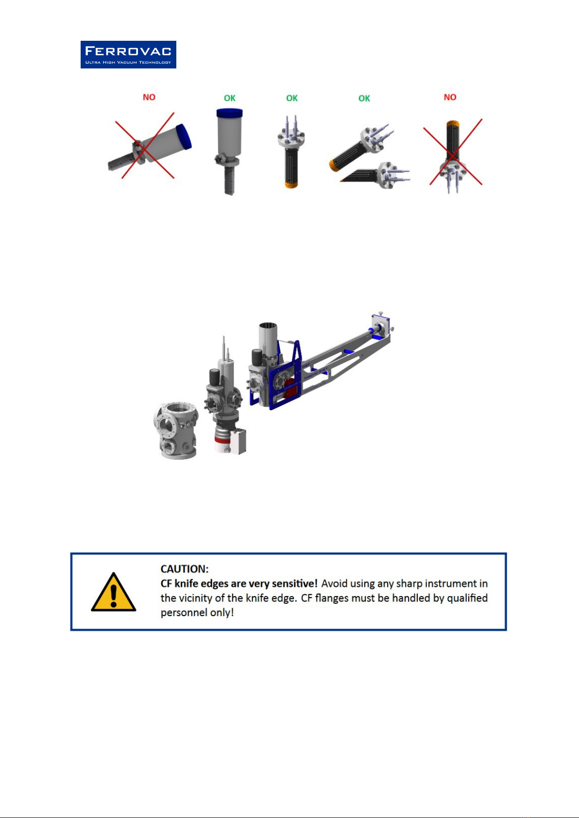
Figure 5: Demonstration of mounting orientations for the CTDH40 and CTH40. The CTDH40
should only mounted in the up-right orientation.
Figure 6: Schematic example for the usage of the VSCT40 with a chamber together with our
NexGeneration UHV suitcase.
(Be aware that the valve and short flanges of the VSCT40 have tapped holes.)

Operation Manual
CTH40/CTDH40/VSCT40
Page|15 /28
Rev. C
4.2 Temperature measurement and heating
The CTH40 and CTDH40 have a Pt100 temperature sensor installed inside. For the wiring diagram please
refer to Fig. 10 (and Fig. 11 if you have bought the respective cable).
Useful items:
• CABCTH40HTB4M, CABCTH40HT4M or your own cabling
• Multimeter
• Standard laboratory power supply for at least 48 W.
• Optional: temperature detection for a Pt100 sensor.
If using CABCTH40HTB4M or CABCTH40HT4M connect the 6-pin connector to the feed-through in the
appropriate orientation.
The temperature measurement can be done as 4-wire or 2-wire measurement. The latter is usually
enough, but less accurate. (A little margin should be taken into account for a 2-wire measurement.) For
the 2-wire measurement just connect −V and +V to a multimeter. If using CABCTH40HTB4M or
CABCTH40HT4M connect one black (-) and one yellow (+) banana plug to a multimeter for resistance
measurement. Leave the other two disconnected without producing a short circuit. If a 4-wire
measurement should be performed, a constant current of 1 mA is recommended. Connect −I and +I for
the current and −V and +V for the voltage measurement. If using CABCTH40HTB4M or CABCTH40HT4M
use one black (-) and one yellow (+) banana plug for the current and the other two for the voltage
measurement. For resistance-temperature conversion refer to Fig. 12 or the respective data for Pt100
sensors from internet.

Operation Manual
CTH40/CTDH40/VSCT40
Page|16 /28
Rev. C
When using the heating coil, the device should be under vacuum! Before connecting, make sure that the
output of the power supply is switched off. Connect the blue (−IF ) and red (+IF ) banana plug to a
standard laboratory supply. A current of up to 4 A (about 12 V) can be applied to the heating coil.
Further details for cool-down and warm-up will be described in the sections below. For available
upgrades and options, see Sec. 11. A 4-wire measurement electronics is not available at the moment
(and usually not necessary).
4.3 Installation for cool-down
The responsible body is liable to take care of a proper cooling set-up and the respective safety
measures. The installation of a gas handling and cooling system should only be done by trained service
personnel. Please read section 6 and decide for an adequate set-up in your laboratory for installation on
the system. In general a bake-out of the cryo trap is not necessary, the purpose of the cryo trap is to
shorten transfer times including pump-down procedures. If the system should be baked (see Sec. 8.1)
with the cryo trap installed, please make sure that any heat-sensitive material as plastics etc. can be
removed an no overpressure would built up in the tube system.
5 Preparation for vacuum usage, venting
This section describes the procedures for a potential initial bake-out and general vacuum usage. During
normal operation no regular bake-out is needed. The cryo pump replaces this action to make the pump-
down faster and more efficient.
5.1 Pump-down
Close the valve and unused flanges or additional valves, depending on what is connected in your setup.
Start the roughing pump and subsequently the turbo pumping. If used in warm condition, wait at least
90 min or longer before starting any transfer action of samples. The cooling can be started shortly after
the turbo pumping had been started (not before). Please read section 6.
5.2 Venting
Although the chamber will be opened to air in typical transfer situations, it is recommended to vent the
chamber (and turbo pump) first with clean and dry nitrogen gas (N2). It’ll help with faster pump down
afterward, even when opened to air for a short time. The overpressure for the dry nitrogen should not
exceed 250 mbar as the windows (VSCT40) are not meant to be exposed to large overpressure from
inside the chamber compared to normal atmospheric pressure. They could start leaking.

Operation Manual
CTH40/CTDH40/VSCT40
Page|17 /28
Rev. C
6 Cool-down procedures
6.1 Cool-down of the dewar version CTDH40
For cool-down the dewar of the CTDH40 is filled with liquid nitrogen. (Only operators trained in handling
cryogenic liquids are allowed to perform this task.) The dewar should only be filled up to 3 cm below its
upper rim! Be careful to not spill large amounts of LN2 on sensitive parts in the environment (e.g.
cabling and windows). When the dewar is filled, place the foam cap on top of the dewar.
6.2 Cool-down of the tube version CTH40
This section contains suggestions for step by step procedures to controlled cool down of the CTH40. The
responsible body needs to provide a respective set-up including valves, hoses and connectors, liquid
nitrogen (LN2), vessels and nitrogen gas (N2) cylinders. The set-up should be established by a trained
service personnel. The responsible body is liable for the proper and secure set-up of the nitrogen filling
system respecting the typical security measures for such systems.
6.2.1 Cool-down with a pressurized liquid nitrogen dewar
It is possible to use a liquid nitrogen vessel that is pressurized to pump liquid nitrogen through the
CTH40.
Required equipment:
• Liquid nitrogen cylinder with pressurizing possibility, over pressure valve and venting valve
• Liquid nitrogen vessel for exhaust LN2
• At least 10 liters of liquid nitrogen (the amount of LN2 used depends on the period of time for which
the CTH40 should be cold).
• Valves, connectors and hoses suitable for low temperature usage
• Hose insulation.
Operation Manual
CTH40/CTDH40/VSCT40
Page|18 /28
Rev. C
Connect the outlet of the liquid nitrogen cylinder to the inlet tube (long tube) of the CTH40. A proper
insulation of the hose is recommended (e. g. standard foam insulation for tubes). Do not exert much
force onto the tubes of the CTH40 while fixing the hoses. Connect another insulated hose to the outlet
tube (short tube) and let the emerging liquid flow into a proper vessel that is big enough to hold about 5
liters of LN2. Make sure that the hoses are properly fixed and cannot jump off. Slowly open the valve of
the liquid nitrogen cylinder and put the liquid nitrogen cylinder under small overpressure. First flush the
system with some nitrogen gas and wait until the system and hoses start to cool down. Then slowly
increase the pressure to let liquid nitrogen flow through the system. In general only 0.2-0.3 bar
overpressure are sufficient to achieve a liquid nitrogen flow, depending on the cylinder and hoses used.
The exhaust liquid should be safely collected in a vessel. Keep a steady flow of liquid nitrogen through
the CTH40, such that there is always LN2 in the tube of the CTH40. This generally doesn’t require a large
flow or high pressure.
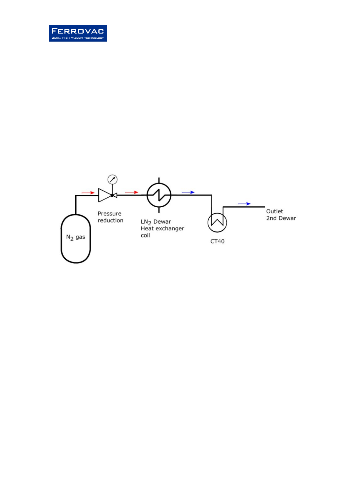
Figure 7: Flow chart for cooling with N2 gas and heat exchanger.
After about half an hour the CTH40 is fully cooled down and reaches its base temperature while the
pressure should drop more than an order of magnitude. Now you can open the valves for transferring
samples. Although the CTH40 won’t warm up immediately, it is recommend not to stop the LN2 flow too
early during transfer. When the transfer is finished stop the nitrogen flow, but don’t open or detach the
hoses as the system is still cold to prevent condensation in the tube.
6.2.2 Cool-down with liquefying N2 gas
A second possibility is to cool-down the CTH40 by liquefying N2 gas with a heat exchanger.
Required equipment:
• High quality N2 gas in a gas cylinder with pressure regulation
• Cu tube with about 10 loops as heat exchanger

Operation Manual
CTH40/CTDH40/VSCT40
Page|19 /28
Rev. C
• Liquid nitrogen vessel big enough to insert the heat exchanger tube
• At least 20 liters of liquid nitrogen(the amount of LN2 used depends on the period of time during
which the CTH40 should be cold)
• Valves, connectors and hoses suitable for low temperature usage
• Hose insulation
Connect the gas cylinder to the heat exchanger coil and the latter to the inlet tube of the CTH40
according to Fig. 7. The outlet of the CTH40 should be connected with another tube which can let the
exhaust LN2 flow into another dewar. Let some warm gas flow through the tubes with a pressure of
approximately 0.5 bar. Then slowly insert the heat exchanger coil into the LN2 dewar and increase the
pressure towards 2 bar. After about 10 min liquid nitrogen should run through the CTH40. Keep the N2
flowing during the transfer, that LN2 runs through the tube. When finished, the pressure can be reduced
to 0.5 bar such that the flow of liquid is stopped. When the hoses are not frozen any more, the heat
exchanger coil can slowly be taken out of the dewar. (Depending on the hose material used, the hoses
might be slightly heated for warm up, but make sure that the hoses don’t become too hot or a high
pressure builds up in the system, to prevent any damage.)
7 Warm-up procedures
7.1 Warm-up CTH40
When the transfer is finished stop the nitrogen flow, but don’t open or detach the hoses as the system is
still cold. (Be aware that some hoses might break when moved in the frozen state.) Also don’t break the
vacuum while the system is cold to prevent water condensation and ice formation on the cryo pump.
(The cryo pump won’t be damaged by water condensation, but it is preferable not to have any water in
the chamber.) Without any further action, it takes several hours until the cryo pump has warmed up.
Therefore the heating coil can be used to fasten the warm-up procedure.
7.1.1 Warm-up by heating with the heating coil
Connect the heating coil as described in section 4.2. Make sure that the chamber is under vacuum
(which should be the case when it is used for cooling). Slowly increase the current up to 2.5A and
carefully monitor the temperature. Be careful towards the end of the warming procedure when the
sensor reaches room temperature. At high currents the temperature might rise fast, therefore the
current should be reduced at the end of the heating procedure. Please be aware that the lower Cu part
of the CTH40 takes usually a little longer than the upper part to warm up. Therefore it is advisable to
wait about 5 min when the sensor had reached 20 C or higher. Afterwards the temperature should be
high enough to vent the chamber without the danger of condensation.

Operation Manual
CTH40/CTDH40/VSCT40
Page|20 /28
Rev. C
The heating has to be switched off before venting the chamber (or otherwise the heating coil can be
damaged).
Some example data can be seen in Fig. 9
An example program for warming up could use the following steps:
Steps
1
2
3
Current (Voltage)
2.5 A (~12 V)
1.8 A (~7.4 V)
1 A (~3.7 V)
Time
5 min
10 min
10 min
Table 1: Suggestion for a warm-up program for CTH40. (Voltage statements are only rough numbers as
they vary with temperature and exact length of the coil.) This program is very similar to the one used for
the test data in Fig. 9. Using this program it takes about 25 min to reach room temperature while it
ensures that everything warms up uniformly.
7.1.2 Warm-up with hot gas
This is a method used for older devices which don’t have a heating coil installed. It costs more time and
nitrogen gas and is therefore not recommended for devices with a heating coil. For faster warm up it is
possible to let warm or hot N2 gas flow through the tube at a pressure of about 0.5 – 1.0 bar. In case the
heat exchanger method is used, it is also possible to dip the heat exchanger coil into hot water (60 C –
80 C) while N2 gas is flowing through the tubes to accelerate the process. Warm up would then take
about 1.5 – 2 hours. The period of time depends on the flow and temperature of the N2 gas.
This manual suits for next models
2
Table of contents
Popular Water Pump manuals by other brands

Crane
Crane Deming 4310 Series Installation, operation & maintenance manual

Danfoss
Danfoss Series 40 M46 Tandem Service manual

Wilo
Wilo Rexa FIT Installation and operating instructions

North Ridge Pumps
North Ridge Pumps VOLTIANA Series Maintenance instructions

Barracuda
Barracuda 93507 owner's manual

Xylem
Xylem rule 7700 GPH instruction manual


Leader Pumps
Leader Pumps DIVERTRON user manual

Dover
Dover PSG Mouvex CC10-24 Installation operation & maintenance

SFA
SFA Sanipit manual

GÜDE
GÜDE HWW 1000 E Original instructions

DentalEZ
DentalEZ RAMVAC Bulldog Maintenance instructions

ITT
ITT Goulds Pumps 3405 Installation, operation and maintenance instructions