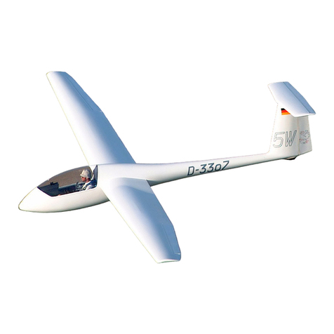
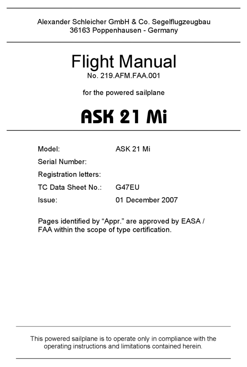
FES Discus 2c Technical specifications

FES FLIGHT MANUAL
Version 1.18
LZ Design d.o.o., ▪ Brod 3D, 1370 Logatec, Slovenia ▪ tel +386 59 948 898

FES Flight Manual, v1.18 May 2020
Page 2 of 35
Table of Content
1. General.................................................................................................................... 5
1.1 Introduction...................................................................................................... 5
1.2 Certification basis.............................................................................................. 5
1.3 Warnings, cautions and notes ............................................................................ 5
1.4 Descriptive data ................................................................................................ 5
1.5 Three-view drawing........................................................................................ 6
1.6 Abbreviations.................................................................................................... 7
1.7 Unit conversions ............................................................................................... 7
2. Limitations ............................................................................................................... 8
2.1 Introduction...................................................................................................... 8
2.2 Airspeed ........................................................................................................... 8
2.3 Airspeed indicator markings ............................................................................... 8
2.4 Powerplant ....................................................................................................... 9
2.4.1 Motor.......................................................................................................... 9
2.4.2 Propeller ..................................................................................................... 9
2.4.3 Battery packs ............................................................................................ 10
2.5 Power-plant instrument markings..................................................................... 10
2.6 Weight ........................................................................................................... 10
2.7 Centre of gravity ............................................................................................. 11
2.8 Approved manoeuvres..................................................................................... 11
2.9 Maneuvering load factors................................................................................. 11
2.10 Flight crew................................................................................................... 11
2.11 Environment conditions ................................................................................ 11
2.12 Minimum equipment..................................................................................... 11
2.13 Aero-tow, winch and auto-tow launching ....................................................... 12
2.14 Other limitations........................................................................................... 12
2.15 Limitations placards...................................................................................... 12
3. Emergency procedures ........................................................................................... 13
3.1 Introduction.................................................................................................... 13
3.2 Canopy jettison............................................................................................... 13
3.3 Bailing out ...................................................................................................... 13
3.3.1 Ballistic parachute...................................................................................... 13
3.4 Stall recovery.................................................................................................. 13
3.5 Spin recovery.................................................................................................. 13
3.6 Spiral dive recovery......................................................................................... 13
3.7 Motor failure ................................................................................................... 13
3.7.1 Motor fails to start ..................................................................................... 13
3.7.2 Power loss during flight.............................................................................. 13
3.8Fire ................................................................................................................ 15
3.8.1 Fire on the ground..................................................................................... 15
3.8.2 Fire inflight................................................................................................ 15
3.9 Other emergencies.......................................................................................... 15
3.9.1 Loss of 12V electrical power inflight ............................................................ 15
4. Normal procedures ................................................................................................. 16
4.1 Introduction.................................................................................................... 16
4.2 Rigging and de-rigging, charging, battery pack installation ................................ 16
4.2.1 Rigging and de-rigging of the sailplane .......................................................... 16
4.2.2 Charging the batteries ............................................................................... 16
4.2.3 Installing the batteries ............................................................................... 17

FES Flight Manual, v1.18 May 2020
Page 3 of 35
4.3 Daily inspection............................................................................................... 17
4.4 Pre-flight inspection ........................................................................................ 18
4.4.1 Preflight test run ....................................................................................... 18
4.5 Normal procedures and recommended speeds .................................................. 19
4.5.1 Aero tow launch........................................................................................... 19
4.5.2 Winch launch ............................................................................................... 19
4.5.3 Car tow launch............................................................................................. 19
4.5.4 Taxiing procedures.......................................................................................... 19
4.5.5 Self-launch and climb................................................................................. 20
4.5.6 Free flight ................................................................................................. 20
4.5.7 Low-speed flight and stall behaviour........................................................... 21
4.5.8 Cruise and climb with a running motor........................................................ 21
4.5.9 Approach .................................................................................................. 23
4.5.10 Landing ..................................................................................................... 23
4.5.11 Flying with water ballast ............................................................................. 24
4.5.12 High altitude flight...................................................................................... 24
4.5.13 Flight in the rain......................................................................................... 25
4.5.14 Aerobatics.................................................................................................. 25
5. Performance .......................................................................................................... 26
5.1 Introduction.................................................................................................... 26
5.2 Approved data ................................................................................................ 26
5.2.1 Airspeed indicator system calibration .......................................................... 26
5.2.2 Stall speeds............................................................................................... 26
5.2.3 Take-off performance (only for self-launch approved types of sailplanes)...... 26
5.3 Non-approved further information .................................................................... 27
5.3.1 Demonstrated crosswind performance ........................................................ 27
5.3.2 Glide performance ..................................................................................... 27
5.3.3 Flight polar................................................................................................ 28
5.3.4 Powered flight performance ....................................................................... 28
5.3.5 Noise data................................................................................................. 29
5.3.6 Electromagnetic interferences .................................................................... 29
6. Weight and balance................................................................................................ 30
6.1 Introduction.................................................................................................... 30
6.2 Weight and balance record and permitted payload-range .................................. 30
6.3 Weight of all non-lifting parts........................................................................... 30
6.4 Maximum weight............................................................................................. 30
7. General sailplane and systems description ............................................................... 31
7.1 Introduction.................................................................................................... 31
7.2 Cockpit controls .............................................................................................. 31
7.3 Instrument panel ............................................................................................ 31
7.4 Landing gear system ....................................................................................... 31
7.5 Seats and safety harness ................................................................................. 31
7.6 Pitot and static system .................................................................................... 31
7.7 Air brakes system............................................................................................ 32
7.8 Baggage Compartment.................................................................................... 32
7.9 Water ballast system ....................................................................................... 32
7.10 Power plant ................................................................................................. 32
7.11 Battery packs ............................................................................................... 32
7.12 Electrical system .......................................................................................... 32
7.13 Miscellaneous equipment .............................................................................. 32
8. Sailplane handling, care and maintenance................................................................ 33

FES Flight Manual, v1.18 May 2020
Page 4 of 35
8.1 Introduction.................................................................................................... 33
8.2 FES inspection periods..................................................................................... 33
8.3 Sailplane alterations or repairs ......................................................................... 33
8.4 Ground handling/road transport ....................................................................... 33
8.5 Sailplane trailer ............................................................................................... 34
8.6 Cleaning and care ........................................................................................... 35
9. Supplements .......................................................................................................... 35
10. Revision history .................................................................................................... 35

FES Flight Manual, v1.18 May 2020
Page 5 of 35
1. General
1.1 Introduction
The FES flight manual has been prepared to provide:
1. Pilots with information for the safe and efficient operation of the sailplanes
equipped with Front Electric Sustainer Self-launcher system.
2. Sailplane manufacturers of specific sailplane types equipped with FES with all the
information necessary to prepare the flight manual of the sailplane after FES
installation.
Chapters of this manual are written as mandated by CS-22.
1.2 Certification basis
This type of powered sailplane has been designed following CS 22 Certification
Specifications for Sailplanes and Powered Sailplanes and according to Special Conditions
for electric powered sailplanes.
1.3 Warnings, cautions and notes
The following definitions apply to warnings, cautions, and notes used in the flight
manual.
Warning:
Non-observation of the corresponding procedure leads to an
immediate or important degradation of flight safety.
Caution:
Non-observation of the corresponding procedure leads to a minor
or extended degradation of flight safety.
Note:
Draws the attention on any particular item not directly related to
safety but is significant or unusual.
1.4 Descriptive data
The sailplane is equipped with a high-tech, powerful FES front electric propulsion
system developed for high performance powered sailplanes. Main parts of the FES system
are:
•Brushless electric motor
•Motor controller
•Foldable propeller
•FES GEN 2 Battery packs, with internal BMS (Battery Management System)
•Charger (600W, 1200W or 2000W)
•FCU (FES control unit) instrument
•LXUI box with Shunt (for current and voltage measurements)
•FCC box (FES connecting circuit)
•Power switch
•DC/DC converter (converts high voltage to 12V)

FES Flight Manual, v1.18 May 2020
Page 6 of 35
1.5 Three-view drawing
Typical FES equipped powered sailplanes are Discus 2c FES and Ventus 2cxa FES.

FES Flight Manual, v1.18 May 2020
Page 7 of 35
1.6 Abbreviations
CAS
Calibrated airspeed is an indicated airspeed of a sailplane, corrected for the
position of the static ports on the fuselage and measurement error of the
instrument. Calibrated airspeed is equal to true airspeed at sea level in the
standard international atmosphere.
C.G.
Centre of gravity
daN
Decanewton
FES
Front Electric Sustainer/Self-launcher
FCU
FES Control Unit
FR
Flight Recorder
h
Hour
IAS
Indicated airspeed is the speed of a sailplane as measured by aircraft speed
indicator connected to its pitot-static system and is uncorrected for the system
error
MOP
Means Of Propulsion sensor
m
Meter
kg
Kilogram
km
Kilometre
s
Second
Ltr
Litre
L/D
Lift to Drag ratio (glide ratio)
°C
Degrees Celsius
1.7 Unit conversions
1 bar = 14,5 pounds per square inch (psi)
1 decanewton (daN) = 2,25 pounds force
1 kilogram (kg) = 2,2 pounds (lbs)
1 meter (m) = 39,4 inches (in.) = 3,28 feet (ft.)
1 millimeter (mm) = 0,0394 inches (in.)
1 liter = 0,2642 U.S. gal
1 square meter (m2) = 10,764 sqare feet (sq.ft)
1 kg/m2= 0,204 lbs/sq.ft
1 m/s = 1,944 knots (kts)
1 km/h = 0,5396 kts
1 kW = 1,34 HP

FES Flight Manual, v1.18 May 2020
Page 8 of 35
2. Limitations
2.1 Introduction
This chapter includes operation limitations, instrument markings, and placards
required for the safe operation of the sailplane equipped with a Front Electric Sustainer
system.
2.2 Airspeed
Airspeed limitations for the use of the FES system and their operational significance
are shown below:
Speed
IAS;
km/h /(kts)
Remarks
VPO
Maximum speed with
a rotating propeller
160 / (86)
Do not exceed this speed with a rotating
propeller (at any power setting)
VPOmin
Minimum speed to
start the motor
80 / (43)
Do not start the motor below this speed
VPOmax
Maximum speed to
start the motor
160 / (86)
Do not start the motor above this speed
Warning:
select your motor start/stop speed correctly:
- flaps must be in a positive setting; (depending on glider type)
- make sure your chosen speed for motor start/stop is at least 8…10 km/h
(4…5 kts) higher than the stall speed for your flight configuration.
2.3 Airspeed indicator markings
FES equipped sailplanes do not have additional indicator markings compared to
pure gliders. Blue line marking on the airspeed indicator can be added, representing a
range of speed with the best rate-of-climb. This range depends on the glider type. Usually,
it is between 80-90km/h, with a positive flap setting.
Marking
(IAS) value or range
Significance
Blue line
80-90km/h
Best rate-of-climb speed

FES Flight Manual, v1.18 May 2020
Page 9 of 35
2.4 Powerplant
Warning:
When FES is installed on an 18m class sailplane like Ventus 2cxa
or Discus 2c, it functions as a sustainer system only. Taking off using the
FES is prohibited unless explicitly stated in the flight manual.
On lighter UL sailplanes like Silent 2 Electro or MiniLAK FES, the system
functions as a self-launch system.
2.4.1 Motor
Motor manufacturer:
LZ design d.o.o.
Motor model:
FES-xxx-Myyy
xxx
- represents the version of the motor for a specific glider type
yyy
- represents the motor length
Note: You can find more details about the motor used on a specific type of
a FES powered sailplane in the separate FES Motor manual.
2.4.2 Propeller
Manufacturer:
LZ design d.o.o.
Model:
FES-xxx-Pv-yyy
xxx
- represents the type of sailplane for which the propeller was designed
v
- represents the version of the propeller for specific glider type
yyy
- represents propeller diameter in mm

FES Flight Manual, v1.18 May 2020
Page 10 of 35
2.4.3 Battery packs
FES needs two battery packs wired in serial. Each battery pack has 14 cells. In total,
the system has 28 cells.
Note: You can find more details about the battery packs which are used on
a specific type of FES powered sailplane in the separate FES Battery pack
manual.
2.5 Power-plant instrument markings
FES power-plant has a dedicated FCU instrument with a high-resolution sunlight-
visible colour display mounted on the instrument panel.
Note: You can find more data about the FCU and its operation in the
separate FES FCU Instrument manual.
2.6 Weight
FES system can be installed only on sailplanes with enough margin in the maximum
weight of non-lifting parts. Total weight of all FES components, including battery
compartment reinforcement ribs, is about 50kg. However, the system requires one 12V
battery as a buffer –usually, the tail battery remains. Other 12V batteries are removed to
save some weight (two standard 12V-7Ah Pb batteries weigh approximately 5kg).
Exact FES system weight depends on the type of sailplane and installed FES
components.
Maximum allowed total voltage of both battery packs
118 V
Minimum allowed total allowed voltage of both battery packs
90 V
Nominal capacity of each cell
40 Ah
Energy storage capacity
4,2 kWh
Maximum voltage per cell
4,16 V
Middle voltage
3,7 V
Minimum voltage of each cell
3,2 V

FES Flight Manual, v1.18 May 2020
Page 11 of 35
2.7 Centre of gravity
Components of the FES system are positioned so that the location of the centre of
gravity (C.G.) is comparable to the one of the pure sailplane. After the installation, we
check the sailplane's C.G. and correct it if necessary.
Warning:
Flying without the motor is prohibited, if not specified
differently for certain type.
Warning:
Flying without the battery packs is prohibited,
if not specified differently for certain type.
2.8 Approved manoeuvres
Aerobatic manoeuvres with FES equipped sailplanes are not permitted, unless it is
specified differently for a certain glider type.
2.9 Maneuvering load factors
Manoeuvring load factors depend on the type of sailplane.
2.10 Flight crew
Flight crew depends on the type of sailplane.
2.11 Kinds of operation
Flights must be conducted in daylight under VFR conditions.
Warning:
Flying under power in heavy rain is not allowed! Make sure you
seal the cover of the battery compartment with plastic tape.
Warning:
Sailplanes equipped with the sustainer system are prohibited from
taking off solely using their own power.
2.12 Minimum equipment
As specified in the flight manual of the pure sailplane.

FES Flight Manual, v1.18 May 2020
Page 12 of 35
2.13 Aero-tow, winch and auto-tow launching
As specified in the flight manual of pure sailplane.
2.14 Other limitations
As specified in the flight manual of pure sailplane.
2.15 Limitations placards
Additional limitation placard must be added for FES equipped sailplanes:
Speed IAS:
km/h
Kts
Power-plant operation
VPO
160
86
Max. engine start
VPOmax
160
86
Min. engine start
VPOmin
80
43

FES Flight Manual, v1.18 May 2020
Page 13 of 35
3. Emergency procedures
3.1 Introduction
According flight manual of pure sailplane.
3.2 Canopy jettison
Warning:
Before canopy jettison, stop the motor and switch OFF power
switch, if there is enough time.
3.3 Bailing out
Warning:
Before you bail out, stop the motor and switch OFF power switch,
if there is enough time.
3.3.1 Ballistic parachute
Sailplanes equipped with a ballistic parachute, have a switch installed which stops
the motor automatically when the parachute is deployed.
3.4 Stall recovery
As specified in flight manual of pure sailplane.
3.5 Spin recovery
As specified in flight manual of pure sailplane.
3.6 Spiral dive recovery
As specified in flight manual of pure sailplane.
3.7 Motor failure
3.7.1 Motor fails to start
If the motor fails to start, continue flying the plane like a pure glider.
Note
:Check the power switch is ON.
The FCU displays a reminder “Check power switch” if you set throttle high
enough.
3.7.2 Power loss during flight
If power is lost during flight, the propeller will windmill. Push the control stick
forward gently, to sustain the desired airspeed! You can perform the following actions to
try and restore power:

FES Flight Manual, v1.18 May 2020
Page 14 of 35
1. Check first if you unintentionally switched OFF the power switch!
Warning: This can happen in gliders that thave the landing gear lever and
the power switch located on the same side of the cockpit when retracting
the landing gear, i.e.
LAK17A&B FES.
If this happens, switch power switch ON and adjust the throttle.
Note:
On earlier software versions (before v2.13), it was necessary to
reduce throttle bar to zero manually; otherwise motor did not start due to
safety. Motor restarted when the throttle was reduced to zero
New versions (from FCU v2.13) automatically reset the throttle!
2. If the power switch is ON:
•Switch OFF the “Power switch”and the FCU.
•Turn ON the FCU and check for strange behaviour.
•If the FCU has no issues switch the power switch ON and try to start the motor.
The motor starts but behaves strangely under power:
•Stop the propeller from the windmilling with the electronic brake.
•When the propeller stops, switch OFF the power switch and the FCU.
If you are not able to stop the propeller with the electronic brake, you will need to land
with a windmilling propeller. Note: it is not possible to stop the propeller by
reducing airspeed. Try to land on both landing wheels simultaneously, to avoid potential
damage of the propeller.
Note:
It is probably better to use a grass runway in good condition if one is
available than a concrete runway.
If the grass runway is in bad shape, use a
concrete runway if one is available.
Warning:
Try to avoid landing into high grass or similar.
Note: The
L/D of a sailplane with a windmilling propeller is reduced only by
a small amount. With enough altitude will have enough time to choose a
suitable landing field.
Please study the FES FCU Instrument manual for exact behaviour and necessary
actions when error and warning messages are displayed.

FES Flight Manual, v1.18 May 2020
Page 15 of 35
3.8 Fire
3.8.1 Fire on the ground
•Switch OFF the “Power switch.”
•Switch OFF all instruments and master switch
•Get out of the cockpit
•Extinguish the fire
3.8.2 Fire inflight
All FES equipped gliders have an independent fire warning system installed. The
system uses a bright red LED to warn a pilot of a possible fire. It is mounted on the top
centre of the instrument panel. The LED starts blinking when the temperature in the
battery compartment reaches 88°C.
In some instances, you can recognize fire by smell also. In that case, we recommend you
to:
•Stop the motor immediately!
•Switch OFF the “Power switch”.
•Open the front ventilation.
•Open canopy side window
•Land as soon as possible, or bail out if need be.
•Extinguish the fire after landing
3.9 Other emergencies
3.9.1 Loss of 12V electrical power inflight
•During soaring:
If electronic instruments (radio, flight computer, FCU etc.) stop working, during
soaring, continue to fly as a pure sailplane. In such a case, you will not be able to
start FES unless FCU still works.
•During a powered flight:
If FCU stops working during a powered flight, the motor will stop. However, the
propeller will continue rotating due to windmilling, and it will not be possible to stop
it. You will need to land with a rotating propeller. Try to land on both landing gears
simultaneously, to avoid damage of propeller.
In case that only some of the instruments stop working during powered flight, but
the motor and FCU are still working fine, you can continue using the motor.

FES Flight Manual, v1.18 May 2020
Page 16 of 35
4. Normal procedures
4.1 Introduction
This chapter provides checklists and explanations of procedures for conducting
normal operating procedures. Normal procedures associated with optional equipment can
be found in Chapter 9.
4.2 Rigging and de-rigging, charging, battery pack installation
4.2.1 Rigging and de-rigging of the sailplane
According to the flight manual of the pure glider version of the aircraft.
Warning:
Make sure that the cable connecting battery packs is not inserted if
they are fixed inside the fuselage.
4.2.2 Charging the batteries
•Valid for FES self-launchers:
FES battery packs must always be fully recharged for self-launching, so that
maximum power for best climb rate is available. This is especially important for:
-cold batteries, when the voltage drop under high power load is bigger
-short runways
-high altitude runways
-hot summer conditions
•Valid for FES self-sustainers:
Before each flying day, battery packs should be recharged, primarily if the system
was used substantially during previous flights and a long cross-country flight is
planned; this way maximum energy will be available when needed.
Note:
It is advisable to recharge the battery packs just a day or two ahead
of a planned flight. However, arrange enough time to complete the charging
process!
Find detailed instructions on the charging of battery packs in a separate FES
Battery pack manual.

FES Flight Manual, v1.18 May 2020
Page 17 of 35
4.2.3 Installing the batteries
Warning:
Make sure both battery packs are fully charged before installation
into the sailplane. Both battery packs must have approximately the same
voltage level of cells –ca. 4.16 V per cell. There should be less than 1V
difference, between the total voltage level of individual battery packs!
1. Check batteries for visual damage
Warning:
Even small, visually detectable damage implies that the affected
battery is not airworthy.
2. Open the battery compartment cover.
3. Check: Power switch (key) OFF
4. Check: Sailplane main switch (fuse) OFF
5. Insert the first pack with terminals facing forward and slide it back to the rear of the
compartment.
6. Insert the second pack with terminals facing rearward.
7. Place a pair of fixation plates in the middle of the rear pack, above the carrying strap
and tighten the fixation knob.
8. Secure the forward battery in the same way as described in step 7.
9. Lift power cables from the side support
10. Plug the shorter cable with an 8mm in the BLUE (or BLACK) housing into the 8mm
socket of front battery pack marked with a minus sign.
11. Plug the longer cable with a 10mm pin in RED housing into the 10mm socket of the
rear battery pack marked with a plus sign.
12. Connect DATA cables to DATA ports on both battery packs.
Caution: Before inserting the DATA cable connector, make sure the
orientation is correct. Align the connector straight with the port before
inserting it; otherwise, pins could be damaged.
13. Close battery compartment cover.
4.3 Daily inspection
Keep in mind the importance of inspections after rigging the glider, and before the
first take-off of the day. As a minimum check the following items. If any problems are
found, they must be corrected before the flight.
•Check the sailplane according to its Flight Manual.
•Check the FES system visually, especially the condition of propeller blades.
•Check fire warning LED by pressing the test button. It must light up brightly,
blinking about one time per second. Change the 9V battery if necessary.

FES Flight Manual, v1.18 May 2020
Page 18 of 35
4.4 Pre-flight inspection
•Check the sailplane itself before a flight.
•Perform a short preflight FES test run as described below.
4.4.1 Preflight test run
After recharging the battery packs, you must perform a short motor run, so that the
FCU can detect the new charge level and store it to the FCU memory.
It is advisable to conduct a test run before the first flight on a flying day.
1. Remove propeller covers and tail dolly.
2. Open the battery compartment cover.
3. Check: Power switch OFF.
4. Switch ON the BMS on each battery pack and wait until the initial check is
completed.
5. Connect the battery packs using the connecting cable.
6. Close the battery compartment cover and seal it with tape.
7. Sit into the glider and close the canopy.
8. Check that no one is around propeller zone, in front of the glider or in line of the
propeller.
9. Switch ON the FCU instrument.
10.Switch ON the power switch.
11.Wait about 5 seconds for the FCU to show battery capacity.
12.Start the motor but use only low power to check proper operation.
Caution
: If you want to test the system at maximum power, somebody
must hold the fuselage, so that glider cannot lift the tail, which could damage
the propeller.
Warning
: Do not run the motor for a longer time on the ground, especially
not at high power! When the motor is not running, it does not cool itself. The
motor temperature can rise very quickly, leading to a damaged motor!
13.Stop the motor and check if automatic positioning is working fine.
14.Switch OFF the power switch.

FES Flight Manual, v1.18 May 2020
Page 19 of 35
4.5 Normal procedures and recommended speeds
As described in the manual of the pure glider version of the sailplane, but keep in
mind that your FES equipped glider has higher wing loading. Adjust speeds accordingly.
4.5.1 Aero tow launch
Before take-off, always switch ON the FCU instrument. Double-check that the
“Power switch” is OFF before somebody approaches the front area of the glider to attach a
tow rope to the hook. The power switch must be OFF during aero-tow!
Warning:
It is not allowed to start the motor during aero tow!
4.5.2 Winch launch
Before take-off, always switch ON the FCU instrument. Double-check that the
“Power switch” is OFF before somebody approaches the front area of the glider to attach
towing cable to the hook. The power switch must be OFF during winch launch!
Warning:
It is not allowed to start the motor during winch launch! Tow rope
must be released before running the motor.
4.5.3 Car tow launch
Before take-off, always switch ON the FCU instrument. Double-check that the
“Power switch” is OFF before somebody approaches the front area of the glider to attach a
tow rope to the hook. The power switch must be OFF during tow!
Warning:
It is not allowed to start the motor during auto tow launch! Tow
rope must be released before running FES motor.
4.5.4 Taxiing procedures
Warning:
Taxiing is not allowed when FES is installed as a sustainer
system!
Your sailplane needs to be factory equipped with a steerable tail wheel and small
wing tip wheels to be suitable for taxiing. Do not taxi with the tail dolly attached.
Taxi only on concrete or grass runways with short grass and smooth surface. Do
not taxi on rough runways; otherwise, you can damage the propeller!
To start taxiing, add a bit more power and decrease it as soon as the plane begins
moving to stop it accelerating. Avoid using the wheel brake and apply it very carefully not
to damage the propeller!

FES Flight Manual, v1.18 May 2020
Page 20 of 35
4.5.5 Self-launch and climb
Warning: Self-launch is not allowed when FES is installed as a sustainer
system!
Before a self-launch always prepare yourself mentally. Think about the actions you
will perform in case of motor failure in different stages of taking-off. Consider wind
conditions, airfield altitude, length of the runway, obstacles at the end of the runway, air
temperature etc.
Do not take off from short runways, with a lot of obstacles and no
possibility for alternatives in case of motor failure.
Caution:
Always take off in the headwind direction!
Self-launch procedure:
1. Check that tail dolly and propeller covers are removed.
2. Sit into the glider, fasten your seat belts and close the canopy.
3. Check that airbrake is closed and locked, and elevator trim set correctly.
4. Set flaps for take-off, depending on sailplane type.
5. Check that motor ventilation is opened.
6. Check that the propeller area and the area in front of the sailplane is free of people
and obstacles. Shout “clear prop” loudly.
7. Switch ON the FCU instrument.
8. Switch ON the power switch and wait until all system parameters are displayed.
9. Ask for take-off permission and wait for the approval.
10.Start the motor by rotating the throttle knob clockwise, set it to low RPM.
11.Gently rotate throttle knob clockwise until maximum power is reached.
12.Accelerate, adjust flaps and gently lift off at an appropriate speed.
13.When safe altitude is reached, reduce power and continue climbing.
14.Retract landing gear.
Caution:
During self-launching, pay attention to the traffic in the circuit
which may not be familiar with electric self-launching sailplanes and may not
expect your aircraft to launch unassisted.
4.5.6 Free flight
As described in the manual of the pure glider version of the sailplane, but keep in
mind that your FES equipped glider has higher wing loading. Adjust speeds accordingly.
Always keep the FCU instrument turned ON during soaring flight.
This manual suits for next models
1
Table of contents
Popular Aircraft manuals by other brands
Magni Gyro
Magni Gyro M-24C Orion Flight manual

Cessna
Cessna 172S Skyhawk Quick reference handbook

Bellanca
Bellanca 300 Viking 17-30 Service and maintenance manual

Ozone
Ozone Zero 3 Pilot's manual
Game Composites
Game Composites GB1 GameBird Airplane Flight Manual
BOMBARDIER
BOMBARDIER CHALLENGER 604 Maintenance manual

