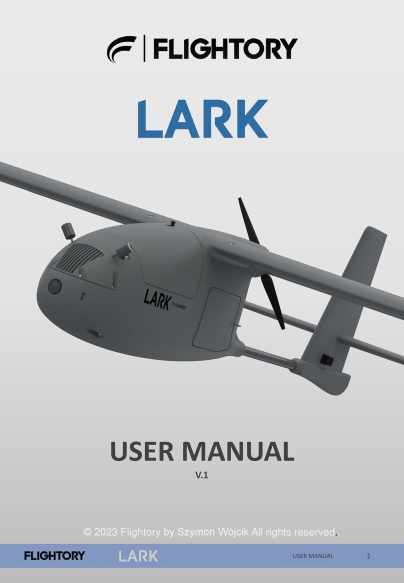
FLIGHTORY talon 1400 User manual

1
USER MANUAL
USER MANUAL
V.1
© 2023 Flightory by Szymon Wójcik All rights reserved.

General Aircraft Data
USER MANUAL 3
General data
Wingspan
1305mm
Wing
area 27.5 dm²
Lenght
830mm
Center of
Gravity 65mm from leading edge
AUW
1500-3300g
Optimal
Cruise Speed 55-65 km/h
Airfoil
Eppler E205
Root Chord
240mm
MAC
211mm
Aspect
Ratio 6.3
Wing
load 54 -120 g / dm²

General Aircraft Data
USER MANUAL 4
The aircraft is a 3D printed UAV platform in a size that combines compactness
and high flight performance. Talon 1400 is in the popular layout with single
push propeller. The design focuses on optimizing flight performance as
possible, accommodating large battery pack and additional equipment, and
modularity. The geometry was carefully refined and studied using CFD and real-
world flight tests. Using optimal equipment and a large 4S6P battery, you can
achieve a flight time of about 4 hours. Easy accessibility for everyone and the
possibility of using different types of equipment is also an important aspect.
The aircraft has two tail variants to fit popular motor sizes. You can decide
which motor you will use. In addition, the nose is also available in two versions
and is fully detachable. You can choose a version with a VTX placed on the nose
along with a 19x19mm FPV camera or a clean option, with the FPV camera
alone. In addition, the nose as well as several other important parts are
available in STEP format, which allows easy editing and customization for more
individual needs. If you need to customize the nose to mount another payload
then you can easily do so. You can have several versions of the nose and
change them during the life of the model depending on the needs of the flight.

CFD Analysis
USER MANUAL 5
The geometry is designed to provide the best possible characteristics. Eppler E205 airfoil
was selected. The shape of the wing and the V-tail stabilizers, as well as their mutual
position and incline angles, were optimized to ensure high performance as well as
longitudinal stability. At around zero AOA, the aircraft shows no pithing moment. Optimal
aerodynamic performance is in the limit from 0 to 2 degrees of AOA and at speeds from
55 to 65 km/h. With a proper center of gravity position of 65mm from the leading edge,
the aircraft does not require any trim, and its natural stability allows it to fly in manual
mode as well, or without a flight controller.

Exploded view
USER MANUAL 6

Reccomended RC Equipment
USER MANUAL 7
Reccomended
electronics
Motor
2830 1200KV Prop Drive / 4108 620KV
Propeller
10x5 (2830 Motor) / 12x10 or 13x8 (4108 Motor)
Flight Controller
Speedybee F405 Wing or any other Mavlink FC
GPS
Matek M10Q or similar GPS with compass
Servos
4x Corona 929MG Metal Gear or similar
ESC
BlHeliS 40A
Battery
4S (max 4S6P 21Ah Li-Ion) or smaller pack / similar LiPo
Receiver
Matek R24-D ELRS or similar
VTX
Digital or analog VTX

Required accessories
USER MANUAL 8
ITEM
QUANTITY
10x530mm Carbon
Tube (MAIN SPAR) 2
6x435mm Carbon
Tube (SECOND SPAR) 4
4x190mm Carbon
Tube (VTAIL SPAR) 4
Thin
CA Glue 20g tube
CA
Activator 1 (optional but useful)
M3
Threaded Insert (Outer Ø5mm,
height
5mm)
20
M3
screw 20
Plastic M6x45mm
screw 4
M6 nut
4
LW
-PLA 1 roll
PLA
Small amount
Polyester
hinge 20x25mm 12
Pen spring
2
Velcro
strap 2
Servo
extension cable 2 (optional)

PARTS LIST - FUSELAGE
USER MANUAL 9
PART MATERIAL
FUS 1
LW-PLA
FUS 2
LW-PLA
FUS 3
LW-PLA
FUS 4
LW-PLA
FUS 5 (2830 motor)
LW-PLA
FUS 5 (4108 motor)
LW-PLA
HATCH MIDDLE 1
LW-PLA
HATCH MIDDLE 2
LW-PLA
HATCH FRONT 1
LW-PLA
HATCH FRONT 2
LW-PLA
NOSE
LW-PLA
NOSE VTX COVER
LW-PLA
NOSE CLEAN
LW-PLA
INNER REINFORCEMENT (
print 2) PLA
NOSE
REINFORCEMENT PLA
BATTERY PAD
PLA
FUS ROOT
L / R PLA
FIREWALL 2830 MOTOR
PLA
FIREWALL 4108 MOTOR
PLA
4108 MOTOR MOUNT
PLA
LOCK 1 (
print 2) PLA
LOCK 2 (
print 2) PLA

PARTS LIST - WINGS
USER MANUAL 10
PART MATERIAL
WING 1 L /R
LW-PLA
WING 2 L /R
LW-PLA
WING 3 L /R
LW-PLA
WINGLET L /R
LW-PLA
AIL L / R
LW-PLA
SERVO COVER (
print 2) PLA
WING ROOT L /R
PLA

PARTS LIST - VTAIL
USER MANUAL 11
PART MATERIAL
V TAIL 1 L /R
LW-PLA
V TAIL 2 L /R
LW-PLA
V TAIL RUDDER L / R
LW-PLA

Print Settings
USER MANUAL 12
Slicer software you need to use is Ultimater Cura. All elements from LW-PLA
are best printed with ready-made settings prepared in a profile that you can
download. Settings are prepared a standard 0.4mm nozzle. Download link is
available on Flightory Blog. Infill in this profile is set to 6%. For this project I
recommend changing it to 3% for most parts. This is sufficient infill
Main features of slicer LW-PLA profile
•layer height: 0,25 mm
•single wall 0,4mm thickness
•3% Gyroid infill.
•Temperature: 235 degrees,
•flow 60%
•fan speed: 0%
The rest of the detailed settings are
saved in the profile.
To print hard PLA or PET-G parts, use
a default profile in CURA called
Draft. Layer height is 0.2 mm, infill
is 20% Grid pattern. Set the
temperature around 220 degrees.
You can fine-tune these parameters
to suit your needs and your printer.

Print Settings
USER MANUAL 13
All parts are suitable for printing on any standard printer with a small
working area. I printed all parts on a 200 x 200mm area. The settings
are just a base that you can change and adjust as needed. The
following pages will list my recommended infill settings for each part.
All elements can be printed without supports, but your printer
may have a problem with some horizontal surfaces in some
places. Depending on the effects, you may then consider turning
on supports for these elements and cleaning the printed
elements afterwards.

Parts Orientation
USER MANUAL 14
Important thing is the correct orientation of the printed parts
to avoid overhangs, and not have to use supports.
Below is the recommended orientation of parts and infill settings.
FUS 1 - 3% gyroid infill
FUS 2 - 3% gyroid infill

Parts Orientation
USER MANUAL 15
FUS 3 - 3% gyroid infill
FUS 4 - 3% gyroid infill

Parts Orientation
USER MANUAL 16
FUS 5 - 3% gyroid infill
NOSE - 4% gyroid infill + 2 walls

Parts Orientation
USER MANUAL 17
NOSE VTX COVER- 4% gyroid infill + 2 walls
HATCH FRONT 1 - 3% gyroid infill

Parts Orientation
USER MANUAL 18
HATCH FRONT 2 - 3% gyroid infill
HATCH MIDDLE 1 - 3% gyroid infill

Parts Orientation
USER MANUAL 19
HATCH MIDDLE 2 - 3% gyroid infill
WING 1 - 3% cubic subdivision infill

Parts Orientation
USER MANUAL 20
WING 2 - 3% cubic subdivision infill
WING 3 - 3% cubic subdivision infill
Table of contents
Other FLIGHTORY Aircraft manuals
Popular Aircraft manuals by other brands
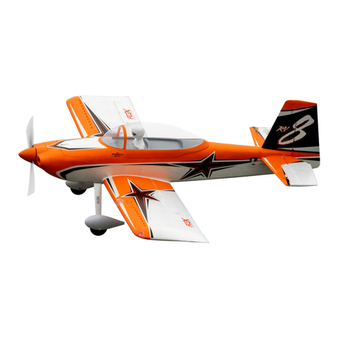
Flex innovations
Flex innovations RV-8 instruction manual

Sky Country
Sky Country Scorpion-3 26 user manual
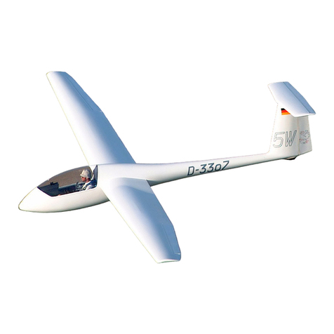
Grob
Grob Astir CS G102 Flight manual
Flying Machines
Flying Machines FM250 VAMPIRE Flight manual
Remos
Remos GX eLITE Pilot operating handbook
Diamond Aircraft
Diamond Aircraft DA 42 NG Service information

