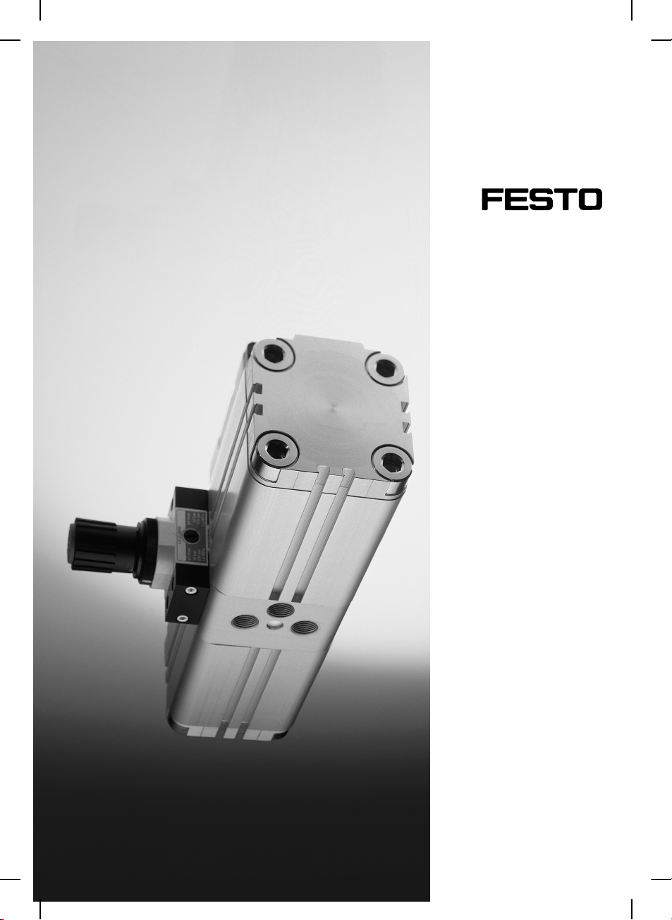
Festo DPA Series User manual

(de) Bedienungs−
anleitung
(en) Operating
instructions
(es) Instrucciones
de utilización
(fr) Notice
d’utilisation
(it) Istruzione
per l’uso
(sv) Bruksanvisning
Druckbooster
Pressure booster
DPA−...
683 877
0405b

DPA−...
Festo DPA−... 0405b
2
Esbedeuten/Symbols/Símbolos/
Symboles/Simboli/Teckenförklaring:
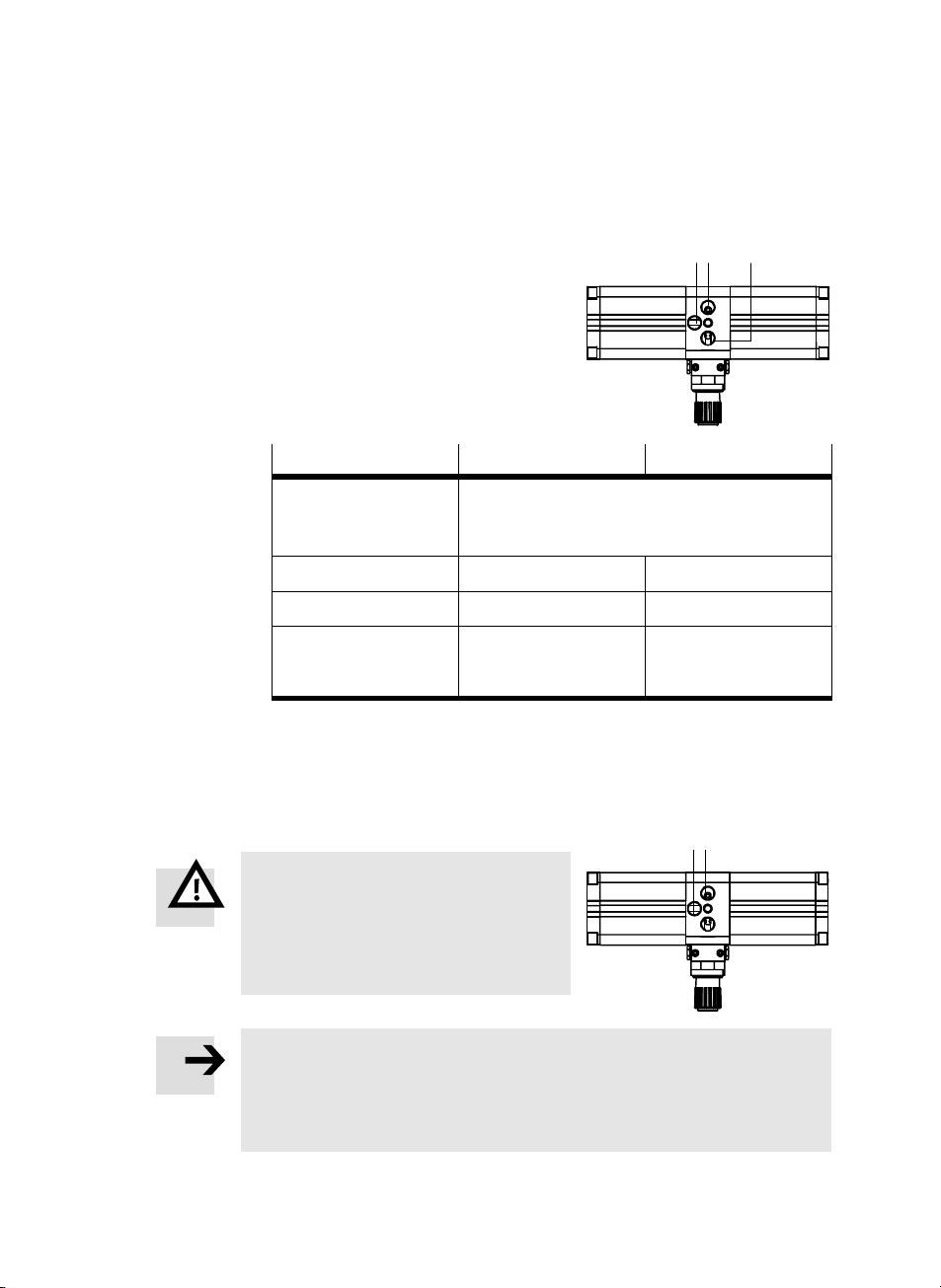
Einbau und Inbetriebnahme nur von qualifi
ziertem Fachpersonal, gemäß Bedienungsan
leitung.
Warnung
Warning, Caution
Atención
Avertissement
Avvertenza
Varning
Hinweis
Please note
Por favor, observar
Note
Nota
Notera
Umwelt
Antipollution
Reciclaje
Recyclage
Riciclaggio
Återvinning
Zubehör
Accessories
Accesorios
Accessoires
Accessori
Tillbehör
Fitting and commissioning to be carried out by
qualified personnel only in accordance with
the operating instructions.
El montaje y la puesta en funcionamiento,
debe ser realizado exclusivamente por perso
nal cualificado y siguiendo las instruccio−nes
de utilización.
Montage et mise en service uniquement par
du personnel agréé, conformément aux
instructions d’utilisation.
Montaggio emessainfunzionedevonoessere
effettuati da personale specializzato ed auto
rizzato in confomità alle istruzioni per l’uso.
Montering och idrifttagning får endast utföras
av auktoriserad fackkunnig personal i
enlighet med denna bruksanvisning.
Deutsch 3. . . . . . . . . . . . . . . . . . . . . . . . . . . . . . . . . . . . . . . . . . . . . . . . . . . . . . . . . . . . . . . . . . . . . .
English 11. . . . . . . . . . . . . . . . . . . . . . . . . . . . . . . . . . . . . . . . . . . . . . . . . . . . . . . . . . . . . . . . . . . . . .
Español 19. . . . . . . . . . . . . . . . . . . . . . . . . . . . . . . . . . . . . . . . . . . . . . . . . . . . . . . . . . . . . . . . . . . . .
Français 27. . . . . . . . . . . . . . . . . . . . . . . . . . . . . . . . . . . . . . . . . . . . . . . . . . . . . . . . . . . . . . . . . . . . .
Italiano 35. . . . . . . . . . . . . . . . . . . . . . . . . . . . . . . . . . . . . . . . . . . . . . . . . . . . . . . . . . . . . . . . . . . . . .
Svenska 43. . . . . . . . . . . . . . . . . . . . . . . . . . . . . . . . . . . . . . . . . . . . . . . . . . . . . . . . . . . . . . . . . . . . .

DPA−...
Festo DPA−... 0405b Deutsch 3
Druckbooster Typ DPA−...Deutsch
1 Bedienteile und Anschlüsse
5
8
4
123
7
6
1Anschlussfür Drucklufteingang
2Anschluss für Hochdruckausgang
3Anschluss für Abluft
4Manometer−Set (Zubehör)
5Einstellknopf für Hochdruck
6Handhilfsbetätigung
7Entlüftungsbohrung desSteuerventils (in der Mitte der Ventilanschlussplatte)
8GewindebohrungenzurBefestigung
Bild1

DPA−...
Festo DPA−... 0405b Deutsch
4
2 Funktion und Anwendung
Durch seine gekoppelten zwei Druckkammern arbeitet der Druckbooster DPA−...
als Doppelkolbenverdichter. Ein Steuerventil leitet den Druck, der konstant am
Anschluss 1ansteht, wechselseitig in die Kompressionskammern. Diese erzeugen
einen Hochdruck bis zum doppelten Wert des Eingangsdrucks. Zur Änderung der
Druckverstärkung dient der Einstellknopf 5.
Bestimmungsgemäß dient der Druckbooster DPA−... zur dauerhaften Erhöhung des
Drucks in Druckluftleitungen.
3 Voraussetzungen für den Produkteinsatz
Hinweis
Unsachgemäße Handhabung erzeugt möglicherweise Fehlfunktionen.
SStellen Sie sicher, dass die Punkte dieses Kapitels stets eingehalten werden.
Dies macht das Produktverhalten ordnungsgemäß und sicher.
SVergleichen Sie die Grenzwerte in dieser
Bedienungsanleitung mit Ihrem aktuellen
Einsatzfall (z.B. Drücke, Kräfte, Momente,
Temperaturen).
Nur die Einhaltung der Belastungsgrenzen
ermöglicht ein Betreiben des Produkts
gemäß der einschlägigen Sicherheitsricht
linien.
SSorgen Sie für Druckluft mit ordnungsge
mäßer Aufbereitung.
SBerücksichtigen Sie die Umweltbedingun
gen vor Ort.
Bild2
LF−... LR−...
Bild3
[°C] [%] [mbar]

DPA−...
Festo DPA−... 0405b Deutsch 5
SBeachten Sie die Vorschriften der Berufsgenossenschaft, des Technischen
Überwachungsvereins oder entsprechende nationale Bestimmungen
(z.B.Sicherheitsvorschriften nach EN 1012, Teil 1).
SVerwenden Sie ein Einschaltventil vom Typ HE−...−D−... oder HEE−...−D−... auf der
Eingangsseite des DPA−... .
Das Einschaltventil darf erst geöffnet werden, wenn sich der Druck in Ihrer
Anlage aufgebaut hat.
SVerwenden Sie ein Einschaltventil vom Typ HE−...−D−... oder HEE−...−D−... auf der
Ausgangsseite des DPA−... .
Dadurch wird ein schnelles Entlüften der nachgeschalteten Anlage ermöglicht.
SEntfernen Sie die Verpackungen mit Ausnahme der Haftetiketten an den Druck
luftanschlüssen (Verschmutzungen).
Die Verpackungen sind vorgesehen für eine Verwertung auf stofflicher Basis
(Ausnahme: Ölpapier = Restmüll).
SBerücksichtigen Sie die Warnungen und Hinweise
amProdukt und
indieser Bedienungsanleitung.
SVerwenden Sie das Produkt im Originalzustand ohne jegliche eigenmächtige
Veränderung.

DPA−...
Festo DPA−... 0405b Deutsch
6
4 Einbau
Mechanisch
SWählen Sie die Befestigungsart für Ihre Anwendung aus der folgenden Tabelle:
Befestigungsart Direktbefestigung Befestigung mit
Haltewinkel Typ HUA−...
Erforderliche
Schraubenzahl
vier Je zwei (im Lieferumfang
der HUA−... enthalten)
Max. zul. Anzugsdreh−
moment 30 Nm
Befestigung
Ó
Ó
Ó
Ó
Ó
Ó
ÓÓÓÓÓÓ
Bild4
Pneumatisch
Hinweis
Falsch dimensionierte Leitungsquerschnitte beeinträchtigen das Zeitverhalten
nachgeschalteter Komponenten.
SVerwenden Sie Schalldämpfer gemäß Zubehör.
Diese machen das Produktverhalten ordnungsgemäß und sicher.
SVerwenden Sie die Mindest−Schlauchquerschnitte nach Bild 6.
Kleinere Nennweiten minimieren den Durchfluss des DPA−... .
SVerwenden Sie das Manometerset Typ DPA−...−MA−SET.
Dadurch kann der erzeugte Ausgangsdruck kontrolliert werden.
SPrüfen Sie, ob ein Druckausgleichsspeicher Typ VZS−... notwendig ist.
Dadurch vermeiden Sie Druckschwankungen.

DPA−...
Festo DPA−... 0405b Deutsch 7
SVerschlauchen Sie die Druckluftanschlüsse
nach Bild 6.
Bei einem Ausgangsdruck größer 10 bar
ist auf die Einhaltung der zulässigen
Grenzwerte für die verwendeten
Anschlusselemente am Ausgang 2zu
achten (ggf. DPA−... verrohren).
Typ DPA−63−... DPA−100−...
Anschlussnummer 1Drucklufteingang
2Hochdruckausgang
3Abluft
Anschlussgröße y’½’
Anzugsdrehmoment max. 25 Nm max. 40 Nm
Schlauchtyp:
für Niederdruck
für Hochdruck PAN−16x2
PAN−12x1,75
PAN−16x2
PAN−16x2
Bild6
5 Inbetriebnahme
Warnung
Schlagartiger Druckluftaustritt verursacht
möglicherweise Verletzungen.
SStellen Sie sicher, dass die Druckluftaus
gänge des DPA−... für Abluft 3und
Hochdruck 2angeschlossen sind.
Hinweis
Hohe Druckluftkräfte beschädigen möglicherweise Armaturen im weiteren
Druckluftpfad.
SStellen Sie sicher, dass Armaturen, die hinter den DPA−... geschaltet werden,
ausgelegt sind für den maximal erreichbaren Hochdruck.
Bild5
123
Bild7
2
3

DPA−...
Festo DPA−... 0405b Deutsch
8
Hinweis
SBerücksichtigen Sie folgende Zusammenhänge:
Einstellung Reaktion
Der eingestellte Hochdruck ist kleiner als
der Eingangsdruck
Der Druckregler am DPA−... entlüftet
bis zum Druckausgleich
Der Eingangsdruck ist stets min. 2 bar geringer
als der eingestellte Hochdruck
DPA−... erreicht den eingestellten
Hochdruck
Erhöhung des Hochdrucks Erhöhung des Luftverbrauchs
Luftvolumen/−strom auf der Eingangsseite
zu gering
Hochdruck schwankt
MaximaleReglereinstellung:
DPA−...−10: typ. 10 bar ... max. 14 bar;
DPA−...−16: typ. 16 bar ... max. 22 bar
Der max. Ausgangsdruck kann um bis
zu 40 % überschritten werden
(produktionsbedingte Streuung der
Reglerfedern)
SVollziehen Sie die Handlungsschritte wie
folgt:
1. Ziehen des Einstellknopfs vom Gehäuse
weg (nur bei DPA−...−10).
2. Drehen des Einstellknopfs 5bis zum
Anschlag gegen den Uhrzeigersinn
(Auslieferungszustand).
3. Belüften des Anschlusses 1am DPA−...
mit dem Eingangsdruck.
4. Drehen des Einstellknopfs auf gewünsch
ten Hochdruck im Uhrzeigersinn.
Die Druckzustände überwachen Zusatz−
Kontrollmanometer gemäß Zubehör
(siehe Bild 10):
Manometer (A): Eingangsdruck
Manometer (B): Hochdruck
Zum Verriegeln:
5. Drücken des Einstellknopfs in Richtung
Gehäuse (nur bei DPA−...−10).
Bild8
5
Bild9
Bild10 (B)(A)
6

DPA−...
Festo DPA−... 0405b Deutsch 9
6 Zubehör
Bezeichnung Typ
Sicherheits−Einschaltventil:
fürEingangsdruck
für Hochdruck
HEL−...
HE−...−D−.../HEE−...−D−...
Schalldämpfer U−y−B; U−½−B; U−M3
Haltewinkel HUA−..
Manometer DPA−...−MA−SET
Druckluftspeicher VZS−...
Reglersicherung LRVS−D−...
Bild11
7 Störungsbeseitigung
Störung Mögliche Ursache Abhilfe
Zu starke Druck
schwankungendes
Hochdrucks
Luftverbrauch der nachfolgen
den Armaturen zu groß
Druckluftspeicher gem. Zubehör
verwenden
Gewünschter
Hochdruck wird
nicht erreicht
Eingangsdruckzugering
Zuviele Verbraucher am
Ausgang
Eingangsdruckerhöhen
Durchfluss zu
gering
Schalldämpfer, Schläuche oder
Verschraubungen mit zu
kleinem Durchfluss verwendet
Nur ausreichend dimensionierte
Bauteileverwenden
Zu kleiner Volumenstromam
Drucklufteingang
Volumenstrom am Druckluftein
gang erhöhen (z.B. mit großem
Druckluftspeicher)
Druckbooster läuft
nicht an
Fehler bei Inbetriebnahme/
ungünst.Betriebsbedingungen
(Ventil in Mittelstellung)
Schaltventil durch Drücken der
Handhilfsbetätigung6(Bild 1
und Bild 10) kurz belüften
Bild12

DPA−...
Festo DPA−... 0405b Deutsch
10
8 Technische Daten
Typ DPA−...
63−10 100−10 63−16 100−16
Teilenummer 184 518 184 519 193 392 188399
Einbaulage Beliebig
Bauart Doppelkolben−Druckverstärker
Medium Getrocknete, gefilterte, ungeölte Druckluft
(Wassergehalt: max. Drucktaupunkt − 20 °C,
Filterfeinheit: min. 40 µm)
Pneumatischer Anschluss G yG ½ G yG ½
Manometeranschluss G xG ¼ G xG ¼
Betriebsdruckbereich
Zul.Eingangsdruck
Erzeugter Hochdruck
min. 2 ... max. 8 bar
4 ... max. 10 bar *) min. 2 ... max. 10 bar
4 ... max. 16 bar *)
Zul. Temperaturbereich + 5 ... + 60 °C
Gewicht 6 kg 13 kg 6 kg 13 kg
*) Bei maximal gespannter Reglerfeder (Drehknopf vollständig im Uhrzeigersinn
gedreht) kann der maximale Ausgangsdruck um 40% überschritten werden:
bei DPA−...−10: max. 14 bar
bei DPA−...−16: max. 22 bar
Bild13

DPA−...
Festo DPA−... 0405b English 11
Pressure booster type DPA−...English
1 Operating parts and connections
5
8
4
123
7
6
1Connection for compressed air input
2Connection for high pressure output
3Connection for exhaust air
4Manometer set (accessory)
5Adjusting knob for high pressure
6Manual override
7Exhaust port of the control valve (in the centre of the valve sub−base)
8Threaded holes for fastening
Fig.1

DPA−...
Festo DPA−... 0405b English
12
2 Method of operation and use
Due to its two coupled pressure chambers, the pressure booster type DPA−... func
tions as a double piston compressor. A control valve conducts the pressure, which
is applied constantly to connection 1, into the compression chambers alternately.
These generate a high pressure up to double the value of the input pressure. The
adjusting knob 5can be used for modifying the pressure amplification.
The pressure booster type DPA−... has been designed for permanently increasing
the pressure in compressed air lines.
3 Conditions of use
Please note
Incorrect handling may lead to incorrect functioning.
SMake sure that the requirements in this chapter are always observed.
The product will then function correctly and safely.
SCompare the maximum values in these
operating instructions with your actual
application (e.g. pressures, forces,
torques, temperatures).
The product can only be operated in ac
cordance with the relevant safety guide
lines if the maximum loading limits are
observed.
SMake sure there is a supply of correctly
prepared compressed air.
STake into acccount the prevailing ambient
conditions.
Fig.2
LF−... LR−...
Fig.3
[°C] [%] [mbar]

DPA−...
Festo DPA−... 0405b English 13
SPlease comply with national and local safety laws and regulations
(e.g. safety regulations as per EN 1012, part 1).
SUse a start−up valve of type HE−...−D−... or HEE−...−D−... on the input side of the
DPA−... .
Do not open the start−up valve until the pressure has built up in your system.
SUse a start−up valve of type HE−...−D−... or HEE−...−D−... on the output side of the
DPA−... .
In this way the downstream switched system can be exhausted quickly.
SRemove the packing with the exception of the adhesive labels on the
compressed air connections (to prevent dirt from entering).
The packaging is intended for recycling, except for oiled paper: This must
bedisposedof ).
SPlease observe the warnings and instructions
onthe product and
inthese operating instructions.
SUnauthorized product modification is not permitted.

DPA−...
Festo DPA−... 0405b English
14
4 Fitting
Fitting mechanical components
SSelect the fastening method for your application from the following table:
Method of fastening Direct fastening Fastening with support
bracket type HUA−...
Number of screws
required
four Two each (supplied with
the HUA−...)
Max. permitted tightening
torque 30 Nm
Fastening
Ó
Ó
Ó
Ó
Ó
Ó
Ó
Ó
ÓÓÓÓÓÓ
Fig.4
Fitting pneumatic components
Please note
Incorrectly dimensioned tubing cross−sectional areas can impair the timing
behaviour of downstream switched components.
SUse silencers in accordance with the section Accessories".
The product will then function correctly and safely.
SUse the minimum tubing cross−sectional areas as shown in Fig. 6.
Smaller sizes minimize the flow of the DPA−... .
SUse the manometer set type DPA−...−MA−SET.
In this way the generated output pressure can be controlled.
SCheck whether a pressure compensation reservoir type VZS−... is necessary.
In this way you will avoid fluctuations in pressure.

DPA−...
Festo DPA−... 0405b English 15
SConnect the compressed air tubing as
shown in Fig. 6.
With an output pressure greater than
10bar, make sure that the limits for the
connecting elements at output 2are
observed (if necessary fit the DPA−... in
the tubing).
Type DPA−63−... DPA−100−...
Connectionnumber 1Compressed air input
2High pressure output
3Exhaust
Connectionsize y’½’
Tighteningtorque max. 25 Nm max. 40 Nm
Tubing type
for low pressure
for high pressure PAN−16x2
PAN−12x1,75
PAN−16x2
PAN−16x2
Fig.6
5 Commissioning
Warning
The sudden escape of compressed air can
cause injury.
SMake sure that the compressed air
outputs of the DPA−... for exhaust 3and
high pressure 2are connected.
Please note
High compressed air forces can damage equipment further along the com
pressed air path.
SMake sure that equipment switched downstream of the DPA−... is designed
for the maximum high pressure which can be achieved.
Fig.5
123
Fig.7
2
3

DPA−...
Festo DPA−... 0405b English
16
Please note
STake these correlations into account:
Setting Reaction
The set high pressure is less than the input
pressure.
The pressure regulator on the DPA−...
exhausts until pressure is equalized.
The input pressure is always min. 2bar less
than the set high pressure.
DPA−... reaches the set high pressure.
Increasing the high pressure. Increasing the air consumption.
Air volume/current on the input side too low. High pressure fluctuates.
Maximum regulator setting:
DPA−...−10: typ. 10 bar ... max. 14 bar
DPA−...−16: typ. 16 bar ... max. 22 bar.
The max. output pressure can be ex
ceeded by up to 40% (dispersion of the
regulator springs due to production).
SComplete the following steps:
1. Pull the adjusting knob away from the
housing (only with DPA−...−10).
2. Turn the adjusting knob 5as far as
possible in an anti−clockwise direction
(status as supplied).
3. Pressurize connection 1on the DPA−...
with the input pressure.
4. Turn the adjusting knob in a clockwise
direction until the desired high pressure is
set.
The pressure status is monitored by addi
tional control manometers in accordance
with the section Accessories"
(see Fig. 10).
Manometer (A): input pressure
Manometer (B): high pressure
To be locked:
5. Push the adjusting knob towards the
housing (only with DPA−...−10).
Fig.8
5
Fig.9
Fig.10 (B)(A)
6

DPA−...
Festo DPA−... 0405b English 17
6 Accessories
Designation Type
Safety start−up valve
for input pressure
for high pressure
HEL−...
HE−...−D−.../HEE−...−D−...
Silencer U−y−B; U−½−B; U−M3
Support bracket HUA−..
Manometer DPA−...−MA−SET
Compressed air reservoir VZS−...
Regulator lock LRVS−D−...
Fig.11
7 Eliminating faults
Fault Possible cause Remedy
High pressure
fluctuates too
much
Air consumption of
downstream equipment too
high
Use a compressed air reservoir in
accordance with the section
Accessories"
The desired high
pressure is not
reached
Input pressure too low
Toomany consuming
devices on the output
Inrease the input pressure
Flow too low Silencer, tubing or screw
connectors with insufficient
flow used
Use only components of sufficient
sizes
Flow too low Insufficient air volume at
compressed air input
Increase volume at compressed air
input (e.g. with large compressed
air reservoir)
Pressure booster
does not start
Fault in commissioning /
unfavourableoperating
conditions (valve in
mid−position)
Briefly pressurize the switching
valve by pressing the manual
override 6(Fig. 1 and Fig. 10)
Fig.12

DPA−...
Festo DPA−... 0405b English
18
8 Technical specifications
Type DPA−...
63−10 100−10 63−16 100−16
Part number 184 518 184 519 193 392 188399
Mountingposition As desired
Design Double−piston pressure booster
Medium Dried, filtered, non−lubricated compressed air,
(water content: max. pressure dew point − 20 °C,
filter fineness: min. 40 m)
Pneumatic connection G yG ½ G yG ½
Manometer connection G xG ¼ G xG ¼
Operating pressure range
Permitted input pressure
Generated high pressure
min. 2 ... max. 8 bar
4 ... max. 10 bar *) min. 2 ... max. 10 bar
4 ... max. 16 bar *)
Permitted temperature range + 5 ... + 60 °C
Weight 6 kg 13 kg 6 kg 13 kg
*) With max. stressed regulator springs (rotary button turned completely in clockwise
direction) the maximum output pressure can be exceeded by 40%:
with DPA−...−10: max. 14 bar
with DPA−...−16: max. 22 bar.
Fig.13

DPA−...
Festo DPA−... 0405b Español 19
Intensificador de presión tipo DPA−...Español
1 Elementos funcionales y conexiones
5
8
4
123
7
6
1Conexiones para la entrada de aire comprimido
2Conexión para la salida de alta presión
3Conexión para aire de escape
4Juego de manómetros (Accesorio)
5Pomo de ajuste de alta presión
6Accionamiento manual
7Conexión de escape de la válvula de control (en el centro de la placa base de la válvula)
8Agujeros roscados para fijación
Fig.1

DPA−...
Festo DPA−... 0405b Español
20
2 Método de funcionamiento y uso
Debido a sus dos cámaras de presión acopladas, el intensificador de presión tipo
DPA−... funciona como un compresor con cilindro de doble émbolo. Una válvula de
control conduce la presión, que es aplicada constantemente a la conexión 1, al
ternativamente en una y otra cámara de compresión. Esto genera una presión de
hasta el doble del valor de la presión de entrada. El pomo de ajuste 5puede utili
zarse para modificar la amplificación de presión.
El intensificador de presión tipo DPA−... ha sido diseñado para incrementar conti
nuamente la presión en líneas de aire comprimido.
3 Condiciones de uso
Por favor, observar
Un manejo incorrecto puede producir un funcionamiento incorrecto.
SAsegúrese de que se observan siempre los requerimientos de este capítulo.
Con ello, el producto funcionará de forma correcta y fiable.
SCompare los valores máximos especifica
dos en estas instrucciones de funciona
miento con su aplicación actual (p.ej.
presiones, fuerzas, pares, temperaturas).
El producto sólo puede hacerse funcionar
según las correspondientes directrices de
seguridad si se observan los límites de
carga máximos.
SAsegurarse de que el aire de alimentación
se halla convenientemente preparado.
STener en cuenta las condiciones ambien
tales imperantes.
Fig.2
LF−... LR−...
Fig.3
[°C] [%] [mbar]
Other manuals for DPA Series
2
Table of contents
Languages:
Other Festo Extender manuals