manuals.online logo
Brands
  1. Home
  2. •
  3. Brands
  4. •
  5. Festool
  6. •
  7. Power Screwdriver
  8. •
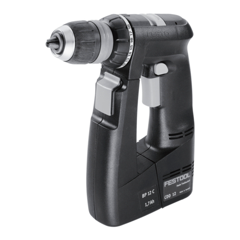
  9. Festool C 12 User manual

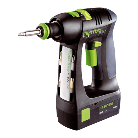
Festool C 12 User manual

468 005_001
Festool GmbH
Wertstraße 20
D-73240 Wendlingen
Tel.: 07024/804-0
Fax: 07024/804-608
http://www.festool.com
C 12
Bedienungsanleitung/Ersatzteilliste*) 4 - 7
Operating Instructions/Spare parts list*) 8 - 11
Mode d’emploi/Liste de pièces de rechange*) 12 - 15
Instrucciones de servicio/Lista de piezas de repuesto*) 16 - 19
Istruzioni d’uso/Elenco parti di ricambio*) 20 - 23
Gebruiksaanwijzing/Lijst met reserveonderdelen*) 24 - 27
Bruksanvisning/Reservdelslista*) 28 - 31
Käyttöohje/Varaosaluettelo*) 31 - 34
Driftsvejledning/Reservedelsliste*) 35 - 38
Bruksanvisning/Reservedelsliste*) 38 - 41
Instruções de uso/Lista de peças sobresselentes*) 42 - 45
Ðóêîâîäñòâî ïî ýêñïëóàòàöèè/Ïåðå÷åíü çàïàñíûõ ÷àñòåé*) 46 - 49
Návod k obsluze/Seznam náhradních dílù*) 50 - 52
Instrukcja obs³ug/Lista czêœci zamiennych*) 53 - 56
Seen at Ideal Tools.
CE-Konformitetserklæring. Vi erklærer på eget ans-
var at dette produktet er i overensstemmelse med
følgende normer eller normative dokumenter: EN 60
745, EN 60 335, EN 55 014, EN 61 000 i henhold til bestem-
melsene i direktivene 73/23/EØF, 98/37/EF, 89/336/EØF.
EG-Konformitätserklärung. Wir erklären in alleini-
ger Verantwortung, dass dieses Produkt mit den
folgenden Normen oder normativen Dokumenten
übereinstimmt: EN 60 745, EN 60 335, EN 55 014, EN 61
000 gemäß den Bestimmungen der Richtlinien 73/23/EWG,
98/37/EG, 89/336/EWG.
467 504/300304
EY-standardinmukaisuusvakuutus. Vakuutamme yk-
sinvastuullisina, että tuote on seuraavien standardien
ja normatiivisten ohjeiden mukainen: EN 60 745,
EN 60 335, EN 55 014, EN 61 000 direktiivien 73/23/EY,
98/37/EY, 89/336/EY määräysten mukaan.
EG-konformitetsförklaring. Vi förklarar i eget ansvar,
att denna produkt stämmer överens med följande nor-
mer och normativa dokument: EN 60 745, EN 60 335,
EN 55 014, EN 61 000 enligt bestämmelserna i direktiven
73/23/EEG, 98/37/EG, 89/336/EEG.
EG-conformiteitsverklaring. Wij verklaren op eigen
verantwoordelijkheid dat dit produkt voldoet aan
de volgende normen of normatieve documenten.
EN 60 745, EN 60 335, EN 55 014, EN 61 000 conform de
richtlijnen 73/23/EEG, 98/37/EG, 89/336/EEG.
CE-Dichiarazione di conformità. Dichiariamo sotto
la nostra esclusiva responsabilità che il presente
prodotto è conforme alle norme e ai documenti
normativi seguenti: EN 60 745, EN 60 335, EN 55 014, EN 61
000 conformemente alle normative delle direttive 73/23/CEE,
98/37/CE, 89/336/CEE.
Oœwiadczenie o zgodnoœci CE. Niniejszym oœwi-
adczamy z ca³¹ odpowiedzialnoœci¹, ¿e wyrób ten
odpowiada nastêpuj¹cym normom wzglêdnie doku-
mentom normatywnym: EN 60 745, EN 60 335, EN 55 014, EN
61 000 zgodnie z postanowieniami wytycznych 73/23/EWG,
98/37/EG, 89/336/EWG.
Leiter Forschung und Entwicklung
Manager Research and Development
Directeur de recherce et développement
Festool GmbH
Wertstr. 20
D-73240 Wendlingen
Dr. Johannes Steimel
EC-Declaration of Conformity: We declare at our
sole responsibility that this product is in conformity
with the following standards or standardised docu-
ments:
EN 60 745, EN 60 335, EN 55 014, EN 61 000 in accordance
with the regulations 73/23/EEC, 98/37/EC, 89/336/EEC.
CE-Declaração de conformidade: Declaramos, sob
a nossa exclusiva responsabilidade, que este pro-
duto corresponde às normas ou aos documentos
normativos citados a seguir:
EN 60 745, EN 60 335, EN 55 014, EN 61 000 segundo as
disposições das directivas 73/23/CEE, 98/37/CE, 89/336/
CEE.
CE-Déclaration de conformité communautaire. Nous
déclarons sous notre propre responsabilité que ce
produit est conforme aux normes ou documents de
normalisation suivants: EN 60 745, EN 60 335, EN 55 014,
EN 61 000 conformément aux prescriptions des directives
73/23/CEE, 98/37/CE, 89/336/CEE.
Çàÿâëåíèå î êîíôîðìíîñòè ÑÅ. Ìû çàÿâëÿåì
â åäèíîëè÷íîé îòâåòñòâåííîñòè, ÷òî äàííîå
èçäåëèå ñîîòâåòñòâóåò òðåáîâàíèÿì ñëåäóþùèõ
ñòàíäàðòîâ èëè íîðìàòèâîâ: EN 60 745, EN 60 335, EN 55 014,
EN 61 000 â ñîîòâåòñòâèè ñ ïîñòàíîâëåíèÿìè äèðåêòèâ
ÅÝÑ 73/23/, ÅÑ 98/37, ÅÝÑ 89/336.
CE-Declaración de conformidad. Declaramos bajo
nuestra exclusiva responsabilidad que este producto
corresponde a las siguientes normas o documentos
normalizados: EN 60 745, EN 60 335, EN 55 014, EN 61 000
conforme a las prescripciones estipuladas en las directrices
73/23/CEE, 98/37/CE, 89/336/CEE.
Prohlášení o souladu s normami CE. Prohlašujeme na
vlastní zodpovìdnost, že tento výrobek odpovídá nás-
ledujícím normám nebo normativním dokumentùm:
EN 60 745, EN 60 335, EN 55 014, EN 61 000 v souladu
s ustanoveními smìrnic 73/23/EHS, 98/37/EHS, 89/336/
EHS.
EF-konformitetserklæring: Vi erklærer at have alene
ansvaret for, at dette produkt er i overensstem-
melse med de følgende normer eller normative
dokumenter:
EN 60 745, EN 60 335, EN 55 014, EN 61 000 i henhold
til bestemmelserne af direktiverne 73/23/EØF, 98/37/EF,
89/336/EØF.
Seen at Ideal Tools.
8
Technical data
Cordless drill/screwdriver C 12
Motor voltage 12 V
Idle-running speed 1. Speed 0 - 450 rpm
2. Speed 0 - 1500 rpm
Max torque
Soft boring (wood) 18 Nm
Hard boring (metal) 30 Nm
Adjustable torque 1. Speed 2 - 7 Nm
2. Speed 0.5 - 2.5 Nm
Chuck capacity 1.5 - 13 mm
Max. drill diameter for wood 25 mm
Max. drill diameter for metal 14 mm
Tool fitting in chuck 1/4“
Weight without battery pack 0.96 kg
Charger LC 45
Supply voltage (input) 230 - 240 V~
Line frequency 50/60 Hz
Charging voltage (output) 7.2 - 18 V=
Charging current 3 A
Quick charge max. 3 A
Compensation charge pulsating
NiCd 1.3 Ah app. 30 min
NiCd 2.4 Ah app. 50 min
NiMH 3.0 Ah app. 70 min
Battery pack BPS 12 C NiCd BPS 12 S NiCd BPS 12 S NiMH
Order number 493 348 492 268 491 821
Voltage 12 V 12 V 12 V
Capacity 1.3 Ah 2.4 Ah 3.0 Ah
Temp. range for charging 5 - 45 °C 5 - 45 °C 5 - 45 °C
Temperature monitoring u s i n g N T C r e s i s t o r
Weight 0.56kg 0.73 kg 0.75 kg
The specified illustrations can be found at the beginning of the operating instructions.
1 Before starting up, please observe
the following
1.1 Intended use
Cordless drills are suitable for drilling metal,
wood, plastics and similar materials, as well as
tightening and screwing in screws (into wood,
up to a diameter of 6 mm).
The LC 45 battery charger is designed for re-
charging the battery pack listed.
The user is liable for damage and injury
resulting from incorrect usage!
1.2 Safety instructions
Before using the machine, read the
enclosed safety instructions and these
operating instructions carefully and
thoroughly.
Save all enclosed documents and pass the ma-
chine with all these documents only.
1.3 Noise and vibration information
Cordless drill/screwdriver
The typical values determined in accordance
with EN 60745 are:
Sound pressure level 65 dB(A)
Sound-power level 76 dB(A)
Measuring uncertainty allowance K = 4 dB
Measured acceleration <2.5 m/s²
The noise level can exceed 85 dB(A)
during operation.
Wear ear protection!
1.4 Wall mounting LC 45
The charger LC 45 has two longitudinal slots on
its rear by which it can be suspended on walls
using two screws (e.g. button-headed or flat
head screw with a shaft diameter of 5 mm).
Screw both screws into the wall 96 mm apart
until the screwhead is protruding from the wall
by approx. 4 mm.
2 Machine settings
Remove the battery pack before any adjust-
ments, maintenance or repair is carried out!
2.1 Exchanging the battery pack
Removing battery pack
Press the two buttons (1.1) and slide the bat-
tery pack forwards to remove.
Inserting battery pack
Slide the battery pack into the holder on the
underside of the handle until it latches into
place (see Fig. 1).
Seen at Ideal Tools.
9
2.2 To change the direction of rotati-
on
The selector button (1.4) determines the direc-
tion of rotation.
Turn button from right to left = clockwise ro-
tation. Turn button from left to right = antic-
lockwise rotation. Selector button in central
position = circuit interlock.
2.3 Shifting speeds
Change only when completely stop-
ped!
Using the shift lever (1.5), the speed can be
changed.
1. Speed: Lever forward - Figure 1 is visible.
2. Speed: Lever backwards - Figure 2 is vi-
sible.
2.4 Torque adjustment
By turning the adjustment ring (1.6) the re-
quired torque can be adjusted. The arrow (1.7)
aligns with the adjusted state.
The machine switches off when the set torque
has been reached. The machine does not start
running again until the ON/OFF switch (1.3) is
released and then pressed again.
Drilling
Drilling symbol on adjustment ring aligns with
the arrow = maximum torque.
Screws
Torque corresponding to setting:
Position 1 = low torque
Position 20 = high torque
3 Tool holding fixture, attachments
3.1 Chuck BF-FX
The chuck is used to clamp drills and bits.
a) Fitting/removing the chuck
Fitting
- Place the chuck on the drill spindle (2.5)
and twist until the hexagon key (2.4) of the
chuck latches into the hexagon socket of the
drill spindle.
- Pull the unlocking ring (2.3) forwards,
press the chuck onto the drill spindle up to
the stop and release the unlocking ring.
Removal
- Pull the unlocking ring forwards and remove
the chuck.
b) Changing tools
- Turn the clamping sleeve (2.2) anti-clockwise
to open the clamping jaws (2.1) (Note: the
spindle is automatically locked when the ma-
chine is switched off).
- Insert the tool into the chuck.
- Clamp the tool by turning the clamping sleeve
clockwise. Always make sure that the tool is
clamped centrally in the chuck.
3.2 Angle attachment DD-AS
The angle attachment permits work (drilling,
screwing) vertical to the machine’s longitudinal
axis.
a) Fitting/removing the angle attach-
ment
Fitting
- Place the angle attachment on the drill spindle
and turn until it catches in the desired position
(Note: The angle attachment can be fitted in
16 different angle settings).
- Lock the angle attachment by turning the
fastening ring (2.7) tightly clockwise.
Removal
- Turn the fastening ring anti-clockwise up to
the stop and remove the angel attachment.
b) Fitting/removal of chuck on angle
attachment
The chuck is fitted on the shaft (2.6) of the
angle attachment in the same way as on the
drill spindle of the machine.
3.3 Eccentric attachment DD-ES
The eccentric attachment is used to hold bits.
It allows screwing close to edges.
a) Fitting/removing the eccentric at-
tachment
The eccentric attachment is fitted/removed in
the same was as the angle attachment (see
Chapter 3.2).
b) Changing tools
- Pull the unlocking ring (2.8) back and remove
the tool and/or insert the new tool.
3.4 CENTROTEC WH-CE toolholder
The CENTROTEC toolholder enables rapid chan-
ges of tools with CENTROTEC shafts.
Do not fit CENTROTEC tools at the round
shaft section in a conventional chuck to
prevent damage to the shaft.
Danger of injury! When changing
tools, handle the tool and its sharp
cutters with special care and wear pro-
tective gloves, if necessary.
a) Fitting/removing CENTROTEC
Fitting
- Pull the release ring (2.11) forwards, place
the toolholder as far as it will go on the drill
spindle (2.5) and let go of the release ring.
Removal
- Pull the release ring forwards and take off the
toolholder.
b) Changing tools
- To insert or remove a tool with CENTROTEC
shaft, pull the green release ring (2.10) back.
On inserting the tool, turn it until its hex shank
arbour (2.9) locks in place in the hexagonal
shank of the drill spindle, and push the tool
into the toolholder as far as it will go.
3.5 Tool holding fixture in the drill
spindle
Bits can be fitted directly in the hexagon socket
holder of the drill spindle (2.5) to make the
machine lighter and shorter.
Seen at Ideal Tools.
10
4 Charge battery pack
To load the battery pack, push it into the holder
(3.1) on the charger up to the stop.
Perform this in reverse to remove the battery
pack from the charger.
The battery type used (NiCd or NiMH) is detec-
ted automatically.
Charging is controlled by a microprocessor.
If a warm NiMH battery pack (>37° C) is inser-
ted, charging will only be carried out at a lower
charge current.
In this case, the charging time is extended.
The LED (3.2) indicates the respective
charging state of the charger.
LED yellow – steady:
Charger is ready for use.
LED green – flashing:
Battery pack being charged.
LED green – steady:
Battery pack fully charged, conservation char-
ge on.
LED red – flashing:
General malfunction, e. g. full contact not
being made, short-circuit, battery pack faul-
ty.
LED red – steady:
Temperature of battery pack is outside per-
missible limit.
It is essential that you read the
instructions in the Chapter „Wor-
king instructions - Maintenance
- Care“.
5 Working with the machine
5.1 Initial operation
Turn on by pressing button (1.3). Depending on
the pressure exerted on the button, the adjust-
ment of running speed can be varied infinitely.
Turn off by releasing the button (1.3).
After releasing the button, the chuck is stopped
and therefore, after-running of the equipment
is prevented.
5.2 Bit storage well
You can insert several bits or bit extensions into
the bit magazine (1.2) with magnetic holder.
5.3 Warning signal
With the following operational statuses, the
machine sounds an acoustic warning signal and
switches off:
Peep at regular intervals
- Battery empty
Triple peep at regular intervals
- Excessive load (torque)
- Machine too warm.
6 lnstructions on application - main-
tenance - care
Please pay attention to the follo-
wing instructions. Otherwise the-
re is a risk of damage to the tool,
charger or battery pack.
- Repairs may only be performed by authorised
technicians. LC 45 charging device: Even after
disconnection from the mains, there is still a
high capacitor voltage on the power output
component on the inside of the device.
- Keep the air vents of the electronic equipment
and the charger clean to guarantee the air
circulation for cooling.
- No metal objects (metal chips) should enter
the charger at the contact points as well as
through the cooling slits into the equipment
(danger of short circuit).
- Only use original Festool battery packs.
Do not use spent and recycled battery packs.
The user shall be liable for damages if Festool
original battery packs are not used.
- Keep the connection contacts of electronic
equipment, charger and battery pack clean.
- By keeping the battery pack in a ready for use
charger, the battery pack will be kept in a state
of readiness by float charging conservation.
- Do not keep discharged battery pack (maxi-
mum one month) attached to charger whe-
never charger is detached from the power
supply (danger of deep discharging).
- A new battery pack or a battery pack not used
for a longer period of time reaches it full ca-
pacity after about 5 charging and discharging
cycles.
- Battery packs should, before charging, be fully
discharged if possible.
Continuous starting of the charging process
shortens the lifespan of the batteries.
- A considerably reduced time of operation per
charging shows that the battery pack is used
up an should be replaced by a new one.
- NiCd battery packs that are not used for lon-
ger periods should be stored in a discharged
state.
Special instructions for NiMH battery
packs:
- The output of NiMH battery packs drops
noticeably at ambient temperatures below 0°
C or above 45° C.
- Do not overload the tool (do not load the tool
excessively so that it comes to a standstill).
- Even if NiMH battery packs are not used, re-
charge them approx. every 4 months so that
they retain their full capacity.
- NiMH battery packs should be left for 60 min.
in the charger after every 10th fast charge
to compensate any differences in capacity
between the cells.
- Because NiMH battery packs discharge auto-
matically, store them preferably at ambient
temperatures of between 0° C and 25° C.
Seen at Ideal Tools.
11
7 Recycling battery packs
Never throw spent battery packs
into domestic waste containers!
Return spent or defective battery packs to dea-
lers, the Festool after-sales service department
or approved waste disposal facilities.
This ensures that they are correctly recycled.
8 Warranty
Our equipment is under warranty for at least 12
months with regard to material or production
faults in accordance with national legislation.
In the EU countries, the warranty period is 24
months (an invoice or delivery note is required
as proof of purchase).
Damage resulting from, in particular, normal
wear and tear, o-verloading, improper handling,
or caused by the user or other damage caused
by not following the operating instructions, or
any fault acknowledged at the time of purchase,
is not covered by the warranty.
Complaints will only be acknowledged if the
equipment has not been dismantled before
being sent back to the suppliers or to an autho-
rised Festool customer support workshop.
Store the operating instructions, safety notes,
spare parts list and proof of purchase in a safe
place.
In addition, the manufacturer’s current warran-
ty conditions apply.
Note: We reserve the right to make changes
to the technical data contained in this infor-
mation as a result of ongoing research and
development work.
Seen at Ideal Tools.

Other Festool Power Screwdriver manuals

Festool C 18 Li User manual

Festool

Festool C 18 Li User manual

Festool C12 EC-TEC User manual

Festool

Festool C12 EC-TEC User manual

Festool T12+3 Installation instructions

Festool

Festool T12+3 Installation instructions

Festool TI 15 User manual

Festool

Festool TI 15 User manual

Festool C 12 Li User manual

Festool

Festool C 12 Li User manual

Festool TDK 12 User manual

Festool

Festool TDK 12 User manual

Festool DWC 18-2500 User manual

Festool

Festool DWC 18-2500 User manual

Festool DWC 18-2500 Installation instructions

Festool

Festool DWC 18-2500 Installation instructions

Festool T18+3 User manual

Festool

Festool T18+3 User manual

Festool T12+3 Installation instructions

Festool

Festool T12+3 Installation instructions

Festool CXS User manual

Festool

Festool CXS User manual

Festool C 12 Li Guide

Festool

Festool C 12 Li Guide

Festool TI 15 User manual

Festool

Festool TI 15 User manual

Festool CXS User manual

Festool

Festool CXS User manual

Festool DWC 18-2500 Installation instructions

Festool

Festool DWC 18-2500 Installation instructions

Festool CDD 9.6 FX User manual

Festool

Festool CDD 9.6 FX User manual

Festool C 12 Li User manual

Festool

Festool C 12 Li User manual

Festool C 18 Li User manual

Festool

Festool C 18 Li User manual

Festool T18+3 User manual

Festool

Festool T18+3 User manual

Festool DWC 18-2500 Installation instructions

Festool

Festool DWC 18-2500 Installation instructions

Festool CXS Installation instructions

Festool

Festool CXS Installation instructions

Festool DWC 18-2500 User manual

Festool

Festool DWC 18-2500 User manual

Festool TDC 18/4 User manual

Festool

Festool TDC 18/4 User manual

Festool DWC 18-2500 User manual

Festool

Festool DWC 18-2500 User manual

Popular Power Screwdriver manuals by other brands

Makita 6837 instruction manual

Makita

Makita 6837 instruction manual

Pattfield Ergo Tools E-AS 18-evo operating instructions

Pattfield Ergo Tools

Pattfield Ergo Tools E-AS 18-evo operating instructions

Parkside PASS 3.6 A1 operation and safety notes original operating instructions

Parkside

Parkside PASS 3.6 A1 operation and safety notes original operating instructions

AEG 4935459427 instruction manual

AEG

AEG 4935459427 instruction manual

Fieldmann FDV 10350-A manual

Fieldmann

Fieldmann FDV 10350-A manual

Mouser ASA-6000 user manual

Mouser

Mouser ASA-6000 user manual

Senco DuraSpin DS200-14v Specifications

Senco

Senco DuraSpin DS200-14v Specifications

Bosch SG250 Operating/safety instructions

Bosch

Bosch SG250 Operating/safety instructions

Hilti ST 1800-A22 Original operating instructions

Hilti

Hilti ST 1800-A22 Original operating instructions

Rapid RP150 MULTI operating instructions

Rapid

Rapid RP150 MULTI operating instructions

Rapesco 1640 Operator's manual

Rapesco

Rapesco 1640 Operator's manual

EINHELL TE-CI 18 Li Original operating instructions

EINHELL

EINHELL TE-CI 18 Li Original operating instructions

Graphite 58G214 instruction manual

Graphite

Graphite 58G214 instruction manual

Draper CD36LITH instructions

Draper

Draper CD36LITH instructions

Sealey CP36S instructions

Sealey

Sealey CP36S instructions

Black & Decker LI2000 instruction manual

Black & Decker

Black & Decker LI2000 instruction manual

HOLZMANN MASCHINEN AKS 45IND user manual

HOLZMANN MASCHINEN

HOLZMANN MASCHINEN AKS 45IND user manual

Chicago Electric 9624 Set up and operating instructions

Chicago Electric

Chicago Electric 9624 Set up and operating instructions

manuals.online logo
manuals.online logoBrands
  • About & Mission
  • Contact us
  • Privacy Policy
  • Terms and Conditions

Copyright 2025 Manuals.Online. All Rights Reserved.